CN203431244U - Three-way ball valve with sealing pre-tightening amount compensation function - Google Patents
Three-way ball valve with sealing pre-tightening amount compensation function Download PDFInfo
- Publication number
- CN203431244U CN203431244U CN201320529562.6U CN201320529562U CN203431244U CN 203431244 U CN203431244 U CN 203431244U CN 201320529562 U CN201320529562 U CN 201320529562U CN 203431244 U CN203431244 U CN 203431244U
- Authority
- CN
- China
- Prior art keywords
- valve body
- way
- valve
- ball
- sealing
- Prior art date
- Legal status (The legal status is an assumption and is not a legal conclusion. Google has not performed a legal analysis and makes no representation as to the accuracy of the status listed.)
- Expired - Lifetime
Links
Images


Landscapes
- Taps Or Cocks (AREA)
- Details Of Valves (AREA)
Abstract
本实用新型公开了一种密封预紧量补偿三通球阀,包括阀座、阀体、三通阀体以及设于三通阀体内的球体,所述的三通阀体通过法兰垫片与阀体相连接,三通阀体通过密封圈一与阀座相连接,所述的三通阀体内腔的三个通道端口与球体之间均设置有密封圈,三通阀体内腔底端设置有旁开凸孔,旁开凸孔内设置有左旋螺杆,左旋螺杆与填料压盖通过内螺纹旋紧连接,所述的左旋螺杆与三通阀体以及阀座之间设置有防静电装置;本实用新型的有益效果:本实用新型生产工艺简单,组装方便,球阀能长期可靠使用,使用寿命长,稳定性好,密封性能好,能很好的导静电,避免了因静电给球阀及介质带来的安全隐患。
This utility model discloses a three-way ball valve with pre-tightening compensation, including a valve seat, a valve body, a three-way valve body, and a ball disposed within the three-way valve body. The three-way valve body is connected to the valve body via a flange gasket and connected to the valve seat via a sealing ring. Sealing rings are provided between the three channel ports of the three-way valve body and the ball. A side-opening protrusion is provided at the bottom of the three-way valve body, and a left-handed screw is disposed within the side-opening protrusion. The left-handed screw is screwed tightly to the packing gland via an internal thread. An anti-static device is provided between the left-handed screw, the three-way valve body, and the valve seat. The advantages of this utility model are: simple manufacturing process, convenient assembly, long-term reliable use of the ball valve, long service life, good stability, good sealing performance, and excellent static electricity conduction, avoiding safety hazards to the ball valve and the medium caused by static electricity.
Description
技术领域technical field
本实用新型涉及一种管道领域,特别涉及一种密封预紧量补偿三通球阀。The utility model relates to the field of pipelines, in particular to a three-way ball valve with sealing pretightening amount compensation.
背景技术Background technique
在管道领域系统中,闸阀、截止阀、球阀这三种阀门应用得最多,它们的缺点也各有千秋,但一般的球阀,在使用中因为配合间隙较大,密封性不够好,容易出现流体残留及泄漏的情况,对阀体的使用寿命会有一定影响而且球阀中的三通球阀,结构复杂,组装麻烦,在使用一段时间之后更容易出现问题,而且没有导静电装置,容易发生因静电发生点燃介质的意外。In the pipeline field system, gate valves, globe valves and ball valves are the three most widely used valves, and their shortcomings also have their own advantages. However, ordinary ball valves are prone to fluid residue and poor sealing performance due to the large fit gap and insufficient sealing performance during use. Leakage will have a certain impact on the service life of the valve body and the three-way ball valve in the ball valve has a complex structure and troublesome assembly. After a period of use, problems are more likely to occur, and there is no static conductive device, which is prone to ignition due to static electricity medium accident.
实用新型内容Utility model content
本实用新型所要解决的技术问题是针对现有技术的不足,提供一种密封预紧量补偿三通球阀。The technical problem to be solved by the utility model is to provide a three-way ball valve with sealing pretightening amount compensation for the deficiencies of the prior art.
为了实现上述目的,本实用新型所采取的措施:In order to achieve the above object, the measures taken by the utility model:
一种密封预紧量补偿三通球阀,包括阀座、阀体、三通阀体以及设于阀体内的球体,所述的三通阀体通过法兰垫片与阀体相连接,三通阀体通过密封圈一与阀座相连接,所述的三通阀体内腔的三个通道端口与球体之间均设置有密封圈,三通阀体内腔底端设置有旁开凸孔,旁开凸孔内设置有左旋螺杆,左旋螺杆与填料压盖通过内螺纹旋紧连接,所述的左旋螺杆与三通阀体以及阀座之间设置有防静电装置,三通阀体内壁涂覆有防腐层,阀体的口部设有过滤网,开凸孔上连接有波纹管。A three-way ball valve with sealing pretightening compensation, comprising a valve seat, a valve body, a three-way valve body and a ball arranged in the valve body, the three-way valve body is connected with the valve body through a flange gasket, and the three-way The valve body is connected with the valve seat through the
所述的旁开凸孔与左旋螺杆之间设有四氟垫圈,所述的四氟垫圈设于旁开凸孔填料函内并与填料压盖连接;A PTFE gasket is provided between the side opening convex hole and the left-handed screw, and the PTFE gasket is arranged in the stuffing box of the side opening convex hole and connected with the packing gland;
所述的球体为三通球体;The sphere is a three-way sphere;
所述的防静电装置为导电弹簧;The anti-static device is a conductive spring;
所述的左旋螺杆顶端连接有手柄,手柄与左旋螺杆之间设有限位片。A handle is connected to the top of the left-handed screw, and a limiting piece is provided between the handle and the left-handed screw.
球体横向设有S形通道,打开阀门的时候,缓冲力更小。The ball has an S-shaped channel in the horizontal direction, and when the valve is opened, the buffer force is smaller.
阀座上设有滚轮,阀体的顶部设有提手,方便移动阀门。There are rollers on the valve seat, and a handle on the top of the valve body, which is convenient for moving the valve.
本实用新型的有益效果:本实用新型生产工艺简单,组装方便,球阀能长期可靠使用,使用寿命长,稳定性好,密封性能好,能很好的导静电,避免了因静电给球阀及介质带来的安全隐患。Beneficial effects of the utility model: the utility model has the advantages of simple production process, convenient assembly, long-term and reliable use of the ball valve, long service life, good stability, good sealing performance, good static conduction, and avoiding the impact of static electricity on the ball valve and the medium. safety hazards.
附图说明Description of drawings
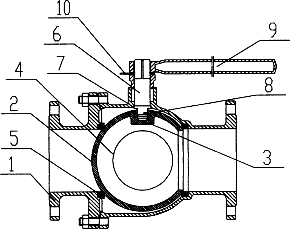
图1、本实用新型结构的正面剖视图。Fig. 1, the front sectional view of structure of the present utility model.
图2、本实用新型结构的俯视剖视图。Fig. 2, the top sectional view of the utility model structure.
具体实施方式Detailed ways
如图1-图2所示一种密封预紧量补偿三通球阀,包括阀座、三通阀体2、阀体1以及设于三通阀体内的球体4,所述的三通阀体内腔的三个通道端口与球体4之间均设置有密封圈,三通阀体2通过法兰垫片5与阀体1相连接,阀体1通过密封圈一与阀座相连接,三通阀体2内腔底端设置有旁开凸孔3,旁开凸孔3内通过四氟垫圈设置有左旋螺杆6,左旋螺杆6与填料压盖7内螺纹旋紧,将其阀座盘固定于三通球体,所述四氟垫圈装在旁开凸孔填料函内有填料压盖装紧起填料密封作用,在左旋螺杆6与阀体及阀座盘之间设置有导电弹簧8,所述的左旋螺杆6采用内装式,螺杆端头凸肩及垫圈加弹簧推力结构,防止旋螺杆因管道压力脱出,所述的左旋螺杆6顶端连接有手柄9,手柄9与左旋螺杆6之间设有限位片10。As shown in Figure 1-Figure 2, a three-way ball valve with sealing pretightening amount compensation includes a valve seat, a three-
本领域内普通的技术人员的简单更改和替换,都是本实用新型的保护范围之内。Simple modifications and replacements by those skilled in the art are within the protection scope of the present utility model.
Claims (7)
Priority Applications (1)
| Application Number | Priority Date | Filing Date | Title |
|---|---|---|---|
| CN201320529562.6U CN203431244U (en) | 2013-08-27 | 2013-08-27 | Three-way ball valve with sealing pre-tightening amount compensation function |
Applications Claiming Priority (1)
| Application Number | Priority Date | Filing Date | Title |
|---|---|---|---|
| CN201320529562.6U CN203431244U (en) | 2013-08-27 | 2013-08-27 | Three-way ball valve with sealing pre-tightening amount compensation function |
Publications (1)
| Publication Number | Publication Date |
|---|---|
| CN203431244U true CN203431244U (en) | 2014-02-12 |
Family
ID=50060281
Family Applications (1)
| Application Number | Title | Priority Date | Filing Date |
|---|---|---|---|
| CN201320529562.6U Expired - Lifetime CN203431244U (en) | 2013-08-27 | 2013-08-27 | Three-way ball valve with sealing pre-tightening amount compensation function |
Country Status (1)
| Country | Link |
|---|---|
| CN (1) | CN203431244U (en) |
Cited By (1)
| Publication number | Priority date | Publication date | Assignee | Title |
|---|---|---|---|---|
| CN106522875A (en) * | 2016-12-07 | 2017-03-22 | 中国石油集团西部钻探工程有限公司 | Well cementation joint |
-
2013
- 2013-08-27 CN CN201320529562.6U patent/CN203431244U/en not_active Expired - Lifetime
Cited By (1)
| Publication number | Priority date | Publication date | Assignee | Title |
|---|---|---|---|---|
| CN106522875A (en) * | 2016-12-07 | 2017-03-22 | 中国石油集团西部钻探工程有限公司 | Well cementation joint |
Similar Documents
| Publication | Publication Date | Title |
|---|---|---|
| CN205592395U (en) | Resistant ultra -low temperature two way seal circle | |
| CN204647484U (en) | A kind of solenoid valve of intake-outlet homonymy | |
| CN203431230U (en) | Integrated type oblique ball valve | |
| CN104565422B (en) | A kind of entirety discharging type cryogenic ball valve | |
| CN204717001U (en) | A kind of ammonia stop valve of high leak tightness | |
| CN204372220U (en) | Thread bush collar nut guide-localization top-loading ball valve | |
| CN205244708U (en) | Singly close union tee of rivers | |
| CN202812225U (en) | Double-acting double-sealed balanced type throttle valve | |
| CN204961861U (en) | Stop valve | |
| CN205331438U (en) | Novel welded structure's of bellows corrugated tube stop valve for ammonia | |
| CN203431214U (en) | Self-guided fast-closing stop valve | |
| CN207906468U (en) | A valve seat with cushioning function | |
| CN204127399U (en) | A kind of for the one-way valve in oil filed pipeline | |
| CN201326768Y (en) | Novel ball valve | |
| CN202327175U (en) | Ball valve | |
| CN204784825U (en) | High temperature high pressure ball valve | |
| CN204828681U (en) | Cooling right -angle type stop valve of industry | |
| CN204512477U (en) | Pressure self-sealing stop valve | |
| CN204755936U (en) | Small dimension stop valve for refrigerating plant | |
| CN203363400U (en) | Axial sealing device | |
| CN203979484U (en) | To pressing from both sides slim Flange Ball Valves | |
| CN204372208U (en) | A kind of gate valve | |
| CN204647536U (en) | A kind of cock-type cut-off spool | |
| CN204647401U (en) | A kind of self tightening filler seal structure of ball seat | |
| CN202812194U (en) | Plug of dual-seal structure |
Legal Events
| Date | Code | Title | Description |
|---|---|---|---|
| C14 | Grant of patent or utility model | ||
| GR01 | Patent grant | ||
| CX01 | Expiry of patent term | ||
| CX01 | Expiry of patent term |
Granted publication date: 20140212 |