CN203409085U - Reverse turning plate bending mould - Google Patents
Reverse turning plate bending mould Download PDFInfo
- Publication number
- CN203409085U CN203409085U CN201320329741.5U CN201320329741U CN203409085U CN 203409085 U CN203409085 U CN 203409085U CN 201320329741 U CN201320329741 U CN 201320329741U CN 203409085 U CN203409085 U CN 203409085U
- Authority
- CN
- China
- Prior art keywords
- floating material
- material block
- length
- mould
- block
- Prior art date
- Legal status (The legal status is an assumption and is not a legal conclusion. Google has not performed a legal analysis and makes no representation as to the accuracy of the status listed.)
- Expired - Fee Related
Links
Images



Landscapes
- Bending Of Plates, Rods, And Pipes (AREA)
Abstract
Description
技术领域technical field
本实用新型关于一种模具,尤其是指一种翻板折弯模具。The utility model relates to a mould, in particular to a turning plate bending mould.
背景技术Background technique
金属工件被弯成一定的形状和角度的零件的成形方法称为弯曲。这些零件大多在压力机上用弯曲模具成形也可用专用折弯机进行折弯、滚弯或者是拉弯。The forming method of a metal workpiece that is bent into a certain shape and angle is called bending. Most of these parts are formed by bending dies on a press, and can also be bent, rolled or stretched with a special bending machine.
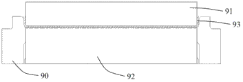
现有的折弯模具,如图1所示,包括一凹模镶块90与一压模镶块91,所述压模镶块91与所述凹模镶块90相配合,在凹模镶块90的凹模内活动设置有一浮料块92,该浮料块92可沿竖直方向上下移动,待加工的工件93放置在该浮料块92上,且两端均超出浮料块92,压模镶块91设置在凹模镶块90的上方,用于推抵浮料块92,带动工件93一同向下移动。加工时,如图2所示,压模镶块91由上而下推抵浮料块92,并配合凹模镶块90凹模的内侧壁的挤压,对工件93的两端进行折弯。成形后的工件93。由于在折弯的过程中,工件93的两端与凹模镶块90凹模的内侧壁直接摩擦接触,所以工件93两端的外壁边缘会出现压痕、压伤,影响了产品的外观,造成产品质量达不到要求,并且由于折弯引起问题,浪费了大量的人力和物力来进行返修。Existing bending mold, as shown in Figure 1, comprises a die
实用新型内容Utility model content
有鉴于上述问题,本实用新型提供了一种翻板折弯模具,包括一凹模镶块、一浮料块与一压模镶块,所述浮料块活动设置于所述凹模镶块的凹模内,所述浮料块可沿竖直方向上下移动,所述压模镶块设置于所述浮料块上方,与所述凹模镶块相配合,其中:In view of the above problems, the utility model provides a flap bending mold, which includes a die insert, a floating material block and a die insert, and the floating material block is movably arranged on the die insert In the die, the floating material block can move up and down in the vertical direction, and the die insert is arranged above the floating material block to cooperate with the die insert, wherein:
所述浮料块的顶部向上凸伸形成一凸块,所述凸块的长度小于所述凹模镶块的凹模的长度,所述压模镶块的长度对应所述凸块的长度;The top of the floating material block protrudes upwards to form a bump, the length of the bump is shorter than the length of the die of the die insert, and the length of the die insert corresponds to the length of the bump;
所述凸块的两侧壁上分别枢接有一翻转件,且所述翻转件的顶面与所述凸块的顶面在同一水平面上,所述翻转件的底部抵靠于所述凹模镶块的两侧的模具的顶部。An overturning piece is pivotally connected to the two side walls of the protrusion, and the top surface of the overturning piece is on the same level as the top surface of the protrusion, and the bottom of the overturning piece is against the die The top of the mold on both sides of the insert.
本实用新型的进一步改进在于,所述翻转件的枢转轴设置于所述凸块侧壁的顶端边缘。A further improvement of the utility model lies in that the pivot shaft of the turning member is arranged on the top edge of the side wall of the protrusion.
工作时,待加工的工件放置在所述浮料块上,工件两端超出浮料块的部分放置于所述翻转件上,所述压模镶块开始向下推抵浮料块,此时,翻转件随浮料块一同向下移动,但是由于翻转件的底部受到凹模镶块的两侧的模具的抵靠作用,无法向下移动,所以翻转件便绕枢转轴开始向上转动,并同时带动着工件的两端一同向上转动,当翻转件向上转动度角之后,即完成了对工件的折弯操作。When working, the workpiece to be processed is placed on the floating material block, and the parts beyond the floating material block at both ends of the workpiece are placed on the flipping piece, and the die insert starts to push down against the floating material block. , the overturning piece moves down together with the floating material block, but because the bottom of the overturning piece is abutted by the molds on both sides of the die insert, it cannot move down, so the overturning piece starts to turn upward around the pivot axis, and At the same time, it drives the two ends of the workpiece to rotate upwards together. When the turning part rotates upwards, the bending operation of the workpiece is completed.
本实用新型的翻板折弯模具,合理的运用了旋转原理对工件进行折弯,避免了普通折弯模具带来的压痕和压伤的弊端。它的优点是:The turnover plate bending mold of the utility model rationally uses the principle of rotation to bend the workpiece, avoiding the disadvantages of indentation and crushing caused by ordinary bending molds. Its advantages are:
1、大大减轻了修模、调模的成本;1. Greatly reduce the cost of mold repair and mold adjustment;
2、消除了产品折弯出现压痕、压伤带来的零件报废的不良风险。2. Eliminate the bad risk of scrapping parts caused by indentation and crushing in product bending.
附图说明Description of drawings
图1是现有技术的折弯模具的结构示意图。Fig. 1 is a structural schematic diagram of a bending die in the prior art.
图2是现有技术的折弯模具的工作状态的示意图。Fig. 2 is a schematic diagram of the working state of the bending die in the prior art.
图3是本实用新型的翻板折弯模具的结构示意图。Fig. 3 is a structural schematic diagram of the flap bending mold of the present invention.
图4是本实用新型的翻板折弯模具的浮料块的结构示意图。Fig. 4 is a schematic structural view of the floating block of the flap bending mold of the present invention.
图5是本实用新型的翻板折弯模具的一种工作状态的示意图。Fig. 5 is a schematic diagram of a working state of the flap bending mold of the present invention.
图6是本实用新型的翻板折弯模具的另一工作状态的示意图。Fig. 6 is a schematic diagram of another working state of the flap bending mold of the present invention.
具体实施方式Detailed ways
为了使本实用新型的目的、技术方案及优点更加清楚明白,以下结合附图及实施例,对本实用新型进行进一步详细说明。应当理解,此处所描述的具体实施例仅用以解释本实用新型,并不用于限定本实用新型。In order to make the purpose, technical solution and advantages of the utility model clearer, the utility model will be further described in detail below in conjunction with the accompanying drawings and embodiments. It should be understood that the specific embodiments described here are only used to explain the utility model, and are not intended to limit the utility model.
配合参看图3所示,本实用新型的翻板折弯模具1,包括一凹模镶块10、一浮料块20与一压模镶块30,所述浮料块20活动设置于所述凹模镶块10的凹模101内,浮料块20可沿竖直方向上下移动,所述压模镶块30设置于所述浮料块20上方,与所述凹模镶块10相配合,其中:Referring to Fig. 3, the panel bending mold 1 of the present utility model includes a
结合图4所示,所述浮料块20的顶部向上凸伸形成一凸块201,所述凸块201的长度小于所述凹模镶块10的凹模101的长度,所述压模镶块30的长度对应所述凸块201的长度;As shown in FIG. 4 , the top of the
所述凸块201的两侧壁上分别枢接有一翻转件202,且所述翻转件202的顶面与所述凸块201的顶面在同一水平面上,所述翻转件202的底部抵靠于所述凹模镶块10的两侧的模具102的顶部。在本实用新型的一较佳实施例中,所述翻转件202的枢转轴设置于所述凸块201侧壁的顶端边缘。A turning
结合图5以及图6所示,工作时,待加工的工件93放置在所述浮料块20上,工件93两端超出浮料块20的部分放置于所述翻转件202上,所述压模镶块30开始向下推抵浮料块20,此时,如图5所示,翻转件202随浮料块20一同向下移动,但是由于翻转件202的底部受到凹模镶块10的两侧的模具102的抵靠作用,无法向下移动,所以翻转件202便绕枢转轴开始向上转动,并同时带动着工件93的两端一同向上转动,如图6所示,当翻转件202向上转动90度之后,即完成了对工件93的折弯操作。5 and 6, when working, the
以上所述仅是本实用新型的较佳实施例而已,并非对本实用新型做任何形式上的限制,虽然本实用新型已以较佳实施例揭露如上,然而并非用以限定本实用新型,任何熟悉本专业的技术人员,在不脱离本实用新型技术方案的范围内,当可利用上述揭示的技术内容作出些许更动或修饰为等同变化的等效实施例,但凡是未脱离本实用新型技术方案的内容,依据本实用新型的技术实质对以上实施例所作的任何简单修改、等同变化与修饰,均仍属于本实用新型技术方案的范围内。The above descriptions are only preferred embodiments of the utility model, and do not limit the utility model in any form. Although the utility model has been disclosed as above with preferred embodiments, it is not used to limit the utility model. Those skilled in the art, without departing from the scope of the technical solution of the utility model, can use the technical content disclosed above to make some changes or modify equivalent embodiments with equivalent changes, but all the technical solutions of the utility model do not depart from Any simple modifications, equivalent changes and modifications made to the above embodiments according to the technical essence of the utility model still belong to the scope of the technical solution of the utility model.
Claims (2)
Priority Applications (1)
| Application Number | Priority Date | Filing Date | Title |
|---|---|---|---|
| CN201320329741.5U CN203409085U (en) | 2013-06-07 | 2013-06-07 | Reverse turning plate bending mould |
Applications Claiming Priority (1)
| Application Number | Priority Date | Filing Date | Title |
|---|---|---|---|
| CN201320329741.5U CN203409085U (en) | 2013-06-07 | 2013-06-07 | Reverse turning plate bending mould |
Publications (1)
| Publication Number | Publication Date |
|---|---|
| CN203409085U true CN203409085U (en) | 2014-01-29 |
Family
ID=49972013
Family Applications (1)
| Application Number | Title | Priority Date | Filing Date |
|---|---|---|---|
| CN201320329741.5U Expired - Fee Related CN203409085U (en) | 2013-06-07 | 2013-06-07 | Reverse turning plate bending mould |
Country Status (1)
| Country | Link |
|---|---|
| CN (1) | CN203409085U (en) |
Cited By (6)
| Publication number | Priority date | Publication date | Assignee | Title |
|---|---|---|---|---|
| CN105964741A (en) * | 2016-05-27 | 2016-09-28 | 中山市甜美电器有限公司 | Frame folding mechanism and frame folding machine |
| CN107042266A (en) * | 2017-05-05 | 2017-08-15 | 吉林大学 | Semiaxis turnover plate type is without impression bender |
| CN108025342A (en) * | 2015-07-13 | 2018-05-11 | 日新制钢株式会社 | The manufacture method of L font square tubes, the manufacture device of L font square tubes and L font square tubes |
| CN108818794A (en) * | 2018-04-28 | 2018-11-16 | 浙江三箭工贸有限公司 | A kind of bamboo frame part stamping equipment and its working method |
| CN109158454A (en) * | 2018-11-03 | 2019-01-08 | 南京金球数控机床股份有限公司 | A kind of high intensity high stability bending machine |
| CN112658078A (en) * | 2020-11-26 | 2021-04-16 | 无锡市诚信洗选设备有限公司 | Pipeline bending mechanism for metallurgical machinery |
-
2013
- 2013-06-07 CN CN201320329741.5U patent/CN203409085U/en not_active Expired - Fee Related
Cited By (7)
| Publication number | Priority date | Publication date | Assignee | Title |
|---|---|---|---|---|
| CN108025342A (en) * | 2015-07-13 | 2018-05-11 | 日新制钢株式会社 | The manufacture method of L font square tubes, the manufacture device of L font square tubes and L font square tubes |
| CN105964741A (en) * | 2016-05-27 | 2016-09-28 | 中山市甜美电器有限公司 | Frame folding mechanism and frame folding machine |
| CN107042266A (en) * | 2017-05-05 | 2017-08-15 | 吉林大学 | Semiaxis turnover plate type is without impression bender |
| CN108818794A (en) * | 2018-04-28 | 2018-11-16 | 浙江三箭工贸有限公司 | A kind of bamboo frame part stamping equipment and its working method |
| CN108818794B (en) * | 2018-04-28 | 2024-02-02 | 浙江三箭工贸有限公司 | Bamboo frame part stamping equipment and working method thereof |
| CN109158454A (en) * | 2018-11-03 | 2019-01-08 | 南京金球数控机床股份有限公司 | A kind of high intensity high stability bending machine |
| CN112658078A (en) * | 2020-11-26 | 2021-04-16 | 无锡市诚信洗选设备有限公司 | Pipeline bending mechanism for metallurgical machinery |
Similar Documents
| Publication | Publication Date | Title |
|---|---|---|
| CN209393764U (en) | A 180 degree forming bending machine | |
| CN104399822B (en) | A bending machine mold capable of processing multi-arc circular surfaces | |
| CN202387840U (en) | Bending and flattening mould for bender | |
| CN204093955U (en) | Stamping embossing die and stamping embossing die set | |
| CN206089442U (en) | Curved graphite jig of 3D curved surface glass heat | |
| CN102513427B (en) | Round rolling forming method and moulds for long and thin metal plate part edges based on brake-press | |
| CN105537399A (en) | Novel four-direction wedge die mechanism and using method thereof | |
| CN203508705U (en) | Forming mechanism for titanium alloy U-shaped piece with double edgefolds | |
| CN202114153U (en) | Stamping die with draw step structure for automotive panel | |
| CN205436708U (en) | Flexible line wheel elbow aluminum alloy excircle bounding wall automated production equipment | |
| CN205702004U (en) | A kind of energy-efficient automobile stamping parts | |
| CN202180135U (en) | Railway-vehicle sliding-plug-door hinge edge-coiling molding die | |
| CN203281735U (en) | Once forming stamping die for brake pad tension spring connecting bent strip | |
| CN103287500B (en) | Top cover beam and forming die of top cover beam and machining method of top cover beam | |
| CN217223069U (en) | Bending mechanism of bending machine | |
| CN206028631U (en) | Automobile control arm forges mould | |
| CN206253525U (en) | A kind of metal plate punching mould | |
| CN117548568A (en) | Special-shaped cross-section, full-contour integrated flanging forming mold and forming method for pallet parts | |
| CN211218205U (en) | Novel edge covering die | |
| CN205571160U (en) | Die for turning -up edge | |
| CN204449015U (en) | A kind of synchronous cutting bending continuous stamping die | |
| CN204308057U (en) | A kind of bending machine die processing multi-radian disc | |
| CN220361892U (en) | One-step stamping forming die | |
| CN207982051U (en) | A kind of diel | |
| CN218109080U (en) | Pendulum block structure for springback shaping of bracket stamping parts |
Legal Events
| Date | Code | Title | Description |
|---|---|---|---|
| C14 | Grant of patent or utility model | ||
| GR01 | Patent grant | ||
| CF01 | Termination of patent right due to non-payment of annual fee |
Granted publication date: 20140129 Termination date: 20190607 |
|
| CF01 | Termination of patent right due to non-payment of annual fee |