CN203405339U - Coupler counter-force hinge seat - Google Patents
Coupler counter-force hinge seat Download PDFInfo
- Publication number
- CN203405339U CN203405339U CN201320480063.2U CN201320480063U CN203405339U CN 203405339 U CN203405339 U CN 203405339U CN 201320480063 U CN201320480063 U CN 201320480063U CN 203405339 U CN203405339 U CN 203405339U
- Authority
- CN
- China
- Prior art keywords
- coupler
- force
- hinge seat
- counter
- reaction force
- Prior art date
- Legal status (The legal status is an assumption and is not a legal conclusion. Google has not performed a legal analysis and makes no representation as to the accuracy of the status listed.)
- Expired - Fee Related
Links
Images

Landscapes
- Seats For Vehicles (AREA)
Abstract
Description
技术领域 technical field
本实用新型涉及一种试验工装,更具体地说,是涉及一种基于转向架参数测定试验台的车辆端部关系综合实验中使用的固定与连接列车车端车钩的车钩反力铰链座装置。 The utility model relates to a test tooling, in particular to a coupler reaction force hinge seat device used in a comprehensive experiment of vehicle end relationship based on a bogie parameter determination test bench for fixing and connecting train car end couplers.
背景技术 Background technique
随着高铁时代的到来,列车时速不断提升,对列车部件的设计提出更高的要求。车端是轨道车辆组成中一个必不可少的重要装置,起到连接各个车厢和在动车驱动下使其顺利通过各种线路曲线弯道的作用。车端的性能直接影响着动车组 ( 列车 ) 的运行品质及运行安全。车端关系试验是指安装在车体端部的部件在列车运行过程中,因列车各车体间相对运动和通过曲线弯道时各部件发生相对移动和转动,通过测量部件的位移和力的变化,测量出车端的刚度及阻尼等参数,为列车动力学分析提供准确的数据。安装在车端的部件主要包括 :贯通道、橡胶外风挡 ( 高速动车组 )、车钩、电器连接器及电线电缆和制动管路等,因此研究上述部件及转向架在车辆通过曲线时的相互关系对于车辆设计及优化至关重要。 With the advent of the era of high-speed rail, the speed of trains continues to increase, which puts forward higher requirements for the design of train components. The car end is an indispensable and important device in the composition of rail vehicles, which plays the role of connecting each car and making it pass through various curves and curves smoothly under the drive of the train. The performance of the car end directly affects the operating quality and safety of the EMU (train). The car end relationship test refers to the relative movement and rotation of the parts installed at the end of the car body during the operation of the train due to the relative movement and rotation of the parts when the train bodies pass through curved curves, by measuring the displacement and force of the parts Changes, measure parameters such as stiffness and damping at the exit end, and provide accurate data for train dynamics analysis. The components installed on the vehicle end mainly include: through passage, rubber outer windshield (high-speed EMU), coupler, electrical connector, wire and cable, and brake pipeline, etc. Therefore, the relationship between the above components and the bogie when the vehicle passes through the curve is studied. Essential for vehicle design and optimization.
目前,对于列车车端关系已有的成果,中国专利授权公告号 102226743A;授权公告日:2011年10月26日;申请日:2011-04-12;实用新型名称:轨道车辆车端关系综合试验台;申请人为吉林大学。中国专利授权公告号 102128723A;授权公告日:2011年07月20日;申请日:2010年12月2日;实用新型名称:车端关系综合试验台;申请人为哈尔滨工业大学。上述两个已有专利并未对其试验台的车钩的安装固定与连接做详细介绍。而实际应用在不同机车上的不同类型的车钩的安装固定装置也不一样,但结构都比较简单,通用性差,不能直接应用到实验台上。因此,为了能够在试验台上根据不同的车钩结构和尺寸完成联接,并完成车钩干涉力检测,研发一种结构简单、通用性强的能够适用于多种类型车钩的固定与连接的车钩反力铰链座装置对于完成列车车端部件的运动干涉试验、功能性试验和研究性试验的轨道车辆车端关系综合试验台是至关重要的。 At present, for the existing achievements of the relationship between the train and the end, the Chinese patent authorization announcement number is 102226743A; the date of the authorization announcement: October 26, 2011; the application date: 2011-04-12; the name of the utility model: the comprehensive test of the relationship between the end of the rail vehicle Taiwan; the applicant is Jilin University. China Patent Authorization Announcement No. 102128723A; Authorized Announcement Date: July 20, 2011; Application Date: December 2, 2010; Utility Model Name: Vehicle-end Relationship Comprehensive Test Bench; The applicant is Harbin Institute of Technology. The above-mentioned two existing patents do not introduce in detail the installation, fixing and connection of the coupler of the test bench. And the mounting fixtures of different types of couplers actually applied on different locomotives are also different, but the structures are relatively simple, and the versatility is poor, so they cannot be directly applied to the test bench. Therefore, in order to complete the connection according to different coupler structures and sizes on the test bench, and complete the coupler interference force detection, a coupler reaction force with simple structure and strong versatility that can be applied to the fixing and connection of various types of couplers is developed. The hinge seat device is very important for the comprehensive test bench of rail vehicle car end relationship for the completion of the motion interference test, functional test and research test of the train car end parts.
实用新型内容 Utility model content
本实用新型所要解决的技术问题是提供一种结构简单、通用性强的列车车端关系综合试验中无车体支撑时车钩的固定与连接的车钩反力铰链座装置。 The technical problem to be solved by the utility model is to provide a coupler reaction force hinge seat device for fixing and connecting the coupler when there is no car body support in the comprehensive test of train car end relationship with simple structure and strong versatility.
为解决上述技术问题,本实用新型提供一种车钩反力铰链座装置,其特征在于:包括两个相同的车钩反力铰链座总成,车钩反力铰链座总成由车钩反力支座与车钩反力支座转接板组成,车钩反力支座中间竖板上开有车钩安装孔,且其中一侧开有两道车钩反力支座T型槽,车钩反力支座转接板上面开有T型槽,在每两道T型槽中间的部位开有两排车钩反力支座转接板安装孔,车钩反力支座通过车钩反力支座转接板T型槽中的T型螺栓与车钩反力支座转接板固定连接。 In order to solve the above technical problems, the utility model provides a coupler reaction force hinge seat device, which is characterized in that it includes two identical coupler reaction force hinge seat assemblies, and the coupler reaction force hinge seat assembly consists of a coupler reaction force support and a The coupler reaction force support adapter plate is composed of a coupler installation hole on the middle vertical plate of the coupler reaction force support, and two T-shaped grooves of the coupler reaction force support are opened on one side, and the coupler reaction force support adapter plate is There are T-shaped slots on the top, and two rows of mounting holes for coupler reaction force support adapter plates are opened in the middle of each two T-shaped slots. The coupler reaction force support passes through the T-shaped slot of the coupler reaction force support adapter plate The T-shaped bolts are fixedly connected with the adapter plate of the coupler reaction force support.
本实用新型的有益效果是: The beneficial effects of the utility model are:
本实用新型所述的车钩反力铰链座装置是在车体上车钩的固定安装座的基础上设计的,设计合理,结构简单,制造难度和成本较低;车钩反力铰链座装置是在轨道车辆车端关系测试中使用的,而轨道车辆车端关系测试是在已有参数试验台的基础上开发的,安装起来比较方便,节省了试验时间,提高了工作效率;车钩反力铰链座装置是根据多种类型列车车端车钩部件设计的,在实验台上可以上下、左右、前后调整以适应不同车端车钩部件,所以说使用的范围比较广,通用性强。 The coupler reaction force hinge seat device described in the utility model is designed on the basis of the fixed mounting seat of the coupler on the car body, and has reasonable design, simple structure, low manufacturing difficulty and low cost; It is used in the vehicle-end relationship test, while the rail vehicle-end relationship test is developed on the basis of the existing parameter test bench, which is more convenient to install, saves test time, and improves work efficiency; the coupler reaction force hinge seat device It is designed according to various types of train end coupler parts, and can be adjusted up and down, left and right, front and back on the test bench to adapt to different car end coupler parts, so it has a wide range of use and strong versatility.
附图说明 Description of drawings
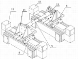
图1是本实用新型实施方式的轴测图; Fig. 1 is the axonometric drawing of the utility model embodiment;
图2是本实用新型实施方式使用状态的轴测图。 Fig. 2 is a perspective view of the usage state of the embodiment of the utility model.
具体实施方式 Detailed ways
参照图1,本实用新型实施方式包括两个相同的车钩反力铰链座总成,车钩反力铰链座总成由车钩反力支座1与车钩反力支座转接板6组成,车钩反力支座中间竖板3上开有车钩安装孔4,且其中一侧开有两道车钩反力支座T型槽2,车钩反力支座转接板上面开有T型槽7,在每两道T型槽中间的部位开有两排车钩反力支座转接板安装孔10,车钩反力支座1通过车钩反力支座转接板6的T型槽7中的T型螺栓5与车钩反力支座转接板6固定连接,车钩9一端的车钩轴叉11通过车钩反力支座1上的车钩反力支座T型槽中的T型螺栓12贯穿车钩轴叉固定在竖板3上。
Referring to Fig. 1, the embodiment of the utility model includes two identical coupler reaction force hinge seat assemblies, the coupler reaction force hinge seat assembly is composed of coupler
参照图2,车钩反力铰链座装置的安装与使用: Referring to Figure 2, the installation and use of the coupler reaction force hinge seat device:
将车钩反力铰链座总成14由穿过车钩反力支座转接板安装孔的螺栓螺母固定在三维测力平台8上,再将三维测力平台安装到运动平台13上,最后将车钩9安装到车钩反力铰链座装置上,根据实验需要的车钩安装高度,先将车钩一端的车钩轴叉11固定在车钩反力铰链座总成14上,再根据车钩的长度调整另一侧车钩反力铰链座总成在三维测力平台上的前后位置,调整好后将车钩的另一端的车钩轴叉固定在该侧车钩反力铰链座总成上。
The coupler reaction force
由于本实验中的运动台可以完成六个自由度的运动,所以可以在实现无车体支撑时车钩固定连接的基础上完成车端关系组件的运动干涉试验、功能性试验和研究性试验。 Because the motion platform in this experiment can complete the movement of six degrees of freedom, it is possible to complete the motion interference test, functional test and research test of the car-end relationship components on the basis of realizing the fixed connection of the coupler when there is no car body support.
Claims (1)
Priority Applications (1)
| Application Number | Priority Date | Filing Date | Title |
|---|---|---|---|
| CN201320480063.2U CN203405339U (en) | 2013-08-07 | 2013-08-07 | Coupler counter-force hinge seat |
Applications Claiming Priority (1)
| Application Number | Priority Date | Filing Date | Title |
|---|---|---|---|
| CN201320480063.2U CN203405339U (en) | 2013-08-07 | 2013-08-07 | Coupler counter-force hinge seat |
Publications (1)
| Publication Number | Publication Date |
|---|---|
| CN203405339U true CN203405339U (en) | 2014-01-22 |
Family
ID=49941269
Family Applications (1)
| Application Number | Title | Priority Date | Filing Date |
|---|---|---|---|
| CN201320480063.2U Expired - Fee Related CN203405339U (en) | 2013-08-07 | 2013-08-07 | Coupler counter-force hinge seat |
Country Status (1)
| Country | Link |
|---|---|
| CN (1) | CN203405339U (en) |
Cited By (2)
| Publication number | Priority date | Publication date | Assignee | Title |
|---|---|---|---|---|
| CN103439121A (en) * | 2013-08-07 | 2013-12-11 | 长春轨道客车股份有限公司 | Car coupler counter-force hinge base device |
| CN111929084A (en) * | 2020-08-28 | 2020-11-13 | 中国铁建高新装备股份有限公司 | Vehicle body test equipment |
-
2013
- 2013-08-07 CN CN201320480063.2U patent/CN203405339U/en not_active Expired - Fee Related
Cited By (2)
| Publication number | Priority date | Publication date | Assignee | Title |
|---|---|---|---|---|
| CN103439121A (en) * | 2013-08-07 | 2013-12-11 | 长春轨道客车股份有限公司 | Car coupler counter-force hinge base device |
| CN111929084A (en) * | 2020-08-28 | 2020-11-13 | 中国铁建高新装备股份有限公司 | Vehicle body test equipment |
Similar Documents
| Publication | Publication Date | Title |
|---|---|---|
| CN201711706U (en) | Automobile body-in-white supporting device | |
| CN103063447B (en) | Automobile test bench | |
| CN203132451U (en) | Integrated detection tool used for simultaneously detecting jitter and thickness difference of two friction surfaces of brake disc | |
| WO2011057496A1 (en) | Vehicle-body integrated test bench | |
| CN103439123B (en) | A kind of device for measuring railway vehicle end relation | |
| CN103439121A (en) | Car coupler counter-force hinge base device | |
| CN101710029A (en) | Ferry sliding table for rail vehicle steering frame parameter detection equipment | |
| CN201834090U (en) | Slidable and foldable chassis assembling trolley for passenger car | |
| CN103558037A (en) | Automobile seat strength test bed with single hydraulic cylinder to act | |
| CN103743577B (en) | Ride toy brake performance test machine | |
| CN103439117A (en) | Vehicle electric wheel multifunctional testing table | |
| CN218121406U (en) | Automatic impact testing mechanism for automobile traction seat | |
| CN117436371A (en) | Method for evaluating the windage braking effect of high-speed trains equipped with windage braking devices | |
| CN202188960U (en) | A frame stiffness test bench | |
| CN204807321U (en) | Rigidity test fixture of gearbox suspension | |
| CN203949618U (en) | A kind of welding deformation is measured frock | |
| CN218272379U (en) | Motor rack for testing counter-dragging type motor | |
| CN103245515B (en) | A kind of automotive seat performance test stationary installation | |
| CN203405341U (en) | Apparatus for measuring rail vehicle end relation | |
| CN202780912U (en) | A testing jig for an automobile differential case | |
| CN120489537A (en) | Coupler load calibration system | |
| CN201731983U (en) | Ferry sliding table for railway vehicle bogie parameter detection devices | |
| CN205300942U (en) | Ten thousand become aluminium alloy car end motion platform | |
| CN105486521B (en) | Ten thousand become aluminium section bar car end motion platform | |
| CN203405338U (en) | Portal frame dovetail guide crossbeam apparatus |
Legal Events
| Date | Code | Title | Description |
|---|---|---|---|
| C14 | Grant of patent or utility model | ||
| GR01 | Patent grant | ||
| CF01 | Termination of patent right due to non-payment of annual fee | ||
| CF01 | Termination of patent right due to non-payment of annual fee |
Granted publication date: 20140122 Termination date: 20190807 |