CN203394728U - Air pump performance test system - Google Patents
Air pump performance test system Download PDFInfo
- Publication number
- CN203394728U CN203394728U CN201320465432.0U CN201320465432U CN203394728U CN 203394728 U CN203394728 U CN 203394728U CN 201320465432 U CN201320465432 U CN 201320465432U CN 203394728 U CN203394728 U CN 203394728U
- Authority
- CN
- China
- Prior art keywords
- air pump
- signal conditioning
- conditioning circuit
- gas
- acquisition module
- Prior art date
- Legal status (The legal status is an assumption and is not a legal conclusion. Google has not performed a legal analysis and makes no representation as to the accuracy of the status listed.)
- Expired - Lifetime
Links
Images

Landscapes
- Air Conditioning Control Device (AREA)
Abstract
一种气泵性能测试系统,包括上位机、数据采集模块、信号调理电路、气泵、气体压力传感器、气体流量传感器、电源电路、气动回路、单向阀、第一三通接头、第二三通接头、储气罐、手动放气阀和安全阀。本实用新型以上位机为系统控制和测试核心,上位机内设有用户操作测试系统软件,上位机发出控制信号,通过数据采集模块和信号调理电路驱动气泵,并将压力传感器的压力信号与流量传感器的流量信号反馈回上位机,测试系统软件根据反馈信号,判断气泵的性能是否正常。该系统结构简单,制造成本低,操作方便,性能稳定,智能化程度高。
An air pump performance testing system, including a host computer, a data acquisition module, a signal conditioning circuit, an air pump, a gas pressure sensor, a gas flow sensor, a power supply circuit, a pneumatic circuit, a one-way valve, a first three-way joint, and a second three-way joint , air storage tank, manual air release valve and safety valve. In the utility model, the upper computer is the core of system control and testing. The upper computer is equipped with user operation test system software. The upper computer sends out control signals, drives the air pump through the data acquisition module and signal conditioning circuit, and combines the pressure signal and flow rate of the pressure sensor. The flow signal of the sensor is fed back to the host computer, and the test system software judges whether the performance of the air pump is normal according to the feedback signal. The system has the advantages of simple structure, low manufacturing cost, convenient operation, stable performance and high degree of intelligence.
Description
技术领域technical field
本实用新型涉及一种电子仪器,特别涉及一种气泵性能测试系统。The utility model relates to an electronic instrument, in particular to an air pump performance testing system.
背景技术Background technique
气泵是从一个封闭空间排除空气或从封闭空间添加空气的一种装置,是气压系统中重要的动力源。电动气泵,是以电力为动力的气泵,通过电力不停地压缩空气,产生气压。气泵的性能影响气压系统的正常运行,而且对于一些控制要求高,精准性要求高的系统,气泵的流量、流速、压力等也要求尽可能的精准。所以,检测气泵性能的优劣是系统稳定的保障。气泵的性能主要是看流量、压力等参数,所以检测气泵的流量、压力这两个重要参数是非常有益的试验。An air pump is a device that removes air from a closed space or adds air from a closed space, and is an important power source in a pneumatic system. The electric air pump is an air pump powered by electricity, which continuously compresses air through electricity to generate air pressure. The performance of the air pump affects the normal operation of the air pressure system, and for some systems with high control requirements and high precision requirements, the flow rate, flow rate, and pressure of the air pump must be as accurate as possible. Therefore, testing the performance of the air pump is the guarantee of system stability. The performance of the air pump mainly depends on parameters such as flow and pressure, so it is a very useful test to detect the two important parameters of the air pump, such as flow and pressure.
在以往的气泵性能测试中,常常是利用常规指示仪表和控制设备,运用人工调节气泵的压力和转速,使之达到国家标准规定的额定值后,在不同环境温度下的情况,进行十几个参数的人工读数、记录;再按照国标的要求进行查表、计算等数据的处理,最后得到气泵的性能参数。这样的操作过程少则1天,多则几天并且最后的结果误差比较大。In the previous air pump performance test, conventional indicating instruments and control equipment were often used to manually adjust the pressure and speed of the air pump to make it reach the rated value stipulated by the national standard. Manual reading and recording of the parameters; then perform data processing such as table lookup and calculation according to the requirements of the national standard, and finally obtain the performance parameters of the air pump. Such an operation process ranges from one day to several days, and the error of the final result is relatively large.
实用新型内容Utility model content
本实用新型的目的,就在于解决上述问题,提供一种气泵性能测试系统。The purpose of this utility model is to solve the above problems and provide an air pump performance testing system.
本实用新型的目的是这样实现的:一种气泵性能测试系统,其包括:The purpose of this utility model is achieved in that a kind of air pump performance testing system comprises:
上位机,内设用户操作测试系统软件,测试时向系统发出控制信号,并根据反馈信号判断气泵的性能;The upper computer is equipped with user-operated test system software, which sends a control signal to the system during the test, and judges the performance of the air pump according to the feedback signal;
数据采集模块,其与上位机电信相连,将上位机的控制信号传输至气泵,并将气体压力传感器的压力反馈信号和气体流量传感器的流量反馈信号传输至上位机;The data acquisition module is connected with the upper computer by telecommunications, transmits the control signal of the upper computer to the air pump, and transmits the pressure feedback signal of the gas pressure sensor and the flow feedback signal of the gas flow sensor to the upper computer;
信号调理电路,其与数据采集模块电信相连;a signal conditioning circuit telecommunications connected to the data acquisition module;
气泵,其与信号调理电路电信相连;an air pump telecommunications connected to the signal conditioning circuit;
气体压力传感器,其与信号调理电路电信相连并将检测到的气体压力数据传输给信号调理电路;a gas pressure sensor telecommunications-connected to the signal conditioning circuit and transmitting detected gas pressure data to the signal conditioning circuit;
气体流量传感器,其与信号调理电路电信相连并将检测到的气体流量数据传输给信号调理电路;a gas flow sensor, which is telecommunications connected to the signal conditioning circuit and transmits the detected gas flow data to the signal conditioning circuit;
气动回路,通过气路分别与气泵、气体压力传感器、气体流量传感器相连;The pneumatic circuit is connected to the air pump, gas pressure sensor, and gas flow sensor respectively through the air circuit;
电源电路,通过电线分别与气泵、数据采集模块、信号调理电路、气体压力传感器、气体流量传感器相连向它们提供工作电源。The power supply circuit is respectively connected with the gas pump, the data acquisition module, the signal conditioning circuit, the gas pressure sensor and the gas flow sensor through wires to provide them with working power.
所述气动回路包括顺序相连的单向阀、第一三通接头、第二三通接头、储气罐和手动放气阀,在第一三通接头的另一接口连接有安全阀;所述气泵连接在单向阀的前端;所述气体压力传感器与第二三通接头的另一接口相连;所述气体流量传感器串接在第二三通接头和储气罐之间。The pneumatic circuit includes a one-way valve connected in sequence, a first three-way joint, a second three-way joint, an air storage tank and a manual air release valve, and a safety valve is connected to the other interface of the first three-way joint; The air pump is connected to the front end of the one-way valve; the gas pressure sensor is connected to the other interface of the second three-way joint; the gas flow sensor is connected in series between the second three-way joint and the gas storage tank.
所述上位机与数据采集模块之间采用串口连接、USB总线连接或PCI总线连接。The host computer and the data acquisition module are connected by a serial port, a USB bus or a PCI bus.
所述数据采集模块具有模拟量输入AD、模拟量输出DA、数字量输入DI、数字量输出DO功能。The data acquisition module has functions of analog input AD, analog output DA, digital input DI, and digital output DO.
所述电源电路向气泵提供220V或110V交流电压,并分别向数据采集模块、信号调理电路、气体压力传感器、气体流量传感器提供24V、12V或5V直流电压。The power supply circuit provides 220V or 110V AC voltage to the air pump, and provides 24V, 12V or 5V DC voltage to the data acquisition module, signal conditioning circuit, gas pressure sensor, and gas flow sensor respectively.
本实用新型能够根据气体压力传感器反馈的压力信号和气体流量传感器反馈的流量信号,判断气泵性能的好坏,并将试验数据存储于上位机,并通过人机界面与操作者交互。该测试系统结构简单、经济,操作方便,测试结果准确。The utility model can judge the performance of the gas pump according to the pressure signal fed back by the gas pressure sensor and the flow signal fed back by the gas flow sensor, and store the test data in the upper computer, and interact with the operator through the man-machine interface. The test system has the advantages of simple structure, economy, convenient operation and accurate test results.
附图说明Description of drawings
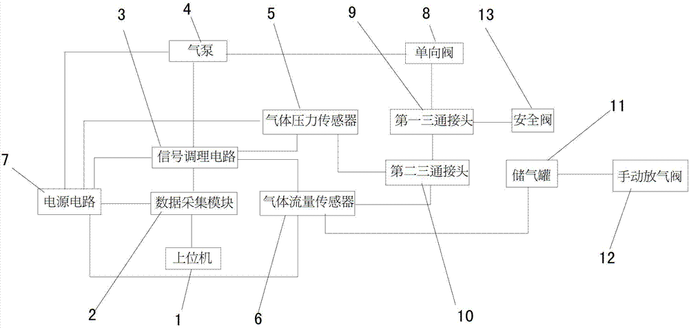
图1是本实用新型测试系统的结构示意图;Fig. 1 is the structural representation of the utility model testing system;
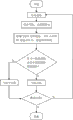
图2是本实用新型的工作程序流程图。Fig. 2 is the working program flowchart of the utility model.
具体实施方式Detailed ways
参见图1,本实用新型的气泵性能测试系统,包括上位机1、数据采集模块2、信号调理电路3、气泵4、气体压力传感器5、气体流量传感器6、电源电路7和气动回路;气动回路包括顺序相连的单向阀8、第一三通接头9、第二三通接头10、储气罐11和手动放气阀12,在第一三通接头9的另一接口连接有安全阀13;上述气泵4连接在单向阀8的前端;气体压力传感器5与第二三通接头10的另一接口相连;气体流量传感器6串接在第二三通接头10和储气罐之间。Referring to Fig. 1, the air pump performance testing system of the present utility model comprises a host computer 1, a
上位机1内设用户操作测试系统软件,上位机1通过数据采集模块2向外发送控制信号,经过信号调理电路3控制气泵4动作,气体压力传感器5和气体流量传感器6同时发出压力反馈信号和流量反馈信号,又通过信号调理电路3、数据采集模块2反馈至上位机1,上位机1对接收到的信号进行处理,从而判断气泵的性能,计算压力值和流量值,将结果通过人机界面与操作者交互,并将数据保存。The upper computer 1 is equipped with user operation test system software. The upper computer 1 sends a control signal to the outside through the
数据采集模块2与上位机1电信相连,可将上位机1的控制信号通过数字DO口输出至气泵4,控制它的通断,也可将气体压力传感器5的压力反馈信号、气体流量传感器6的流量反馈信号通过AD转换输入至上位机1。The
信号调理电路3与数据采集模块2电信相连,该信号调理电路3具有信号隔离、滤波的功能。The
气泵4与信号调理电路电信相连。The
气体压力传感器5与信号调理电路电信相连并将检测到的气体压力数据传输给信号调理电路。The
气体流量传感器6与信号调理电路电信相连并将检测到的气体流量数据传输给信号调理电路。The
电源电路7通过电线分别与气泵、数据采集模块、信号调理电路、气体压力传感器、气体流量传感器相连向它们提供工作电源。电源电路7的输入电源为工频交流电220V 50Hz,通过变压和整流,向气泵提供220V或110V交流电压,以适合不同工作电压的气泵;并分别向数据采集模块、信号调理电路、气体压力传感器、气体流量传感器提供24V、12V或5V直流电压。The power supply circuit 7 is respectively connected with the air pump, the data acquisition module, the signal conditioning circuit, the gas pressure sensor and the gas flow sensor through wires to provide them with working power. The input power of the power supply circuit 7 is industrial frequency AC 220V 50Hz, through voltage transformation and rectification, 220V or 110V AC voltage is provided to the air pump, so as to be suitable for air pumps with different working voltages; , The gas flow sensor provides 24V, 12V or 5V DC voltage.
本实用新型中气动回路包括顺序相连的单向阀8、第一三通接头9、第二三通接头10、储气罐11和手动放气阀12,在第一三通接头的另一接口连接有安全阀13。上述气泵4连接在单向阀9的前端,气体压力传感器5与第二三通接头的另一接口相连,气体流量传感器6串接在第二三通接头和储气罐之间。单向阀8用于向气泵4单向输出气体,防止气体倒流,避免漏气,以及损伤气泵。安全阀13用于气泵4输出管路异常高压、储气罐11内压力过高的情况下进行泄压,防止压力过高对系统造成损坏。异常高压可能发生于管路堵塞、气泵4故障、单向阀8故障等情况。第二三通接头10一侧连接气体压力传感器5,另一侧连接气体流量传感器6,当上位机1发出驱动信号,气泵开始工作,则气体压力传感器5与气体流量传感器6将压力信号和流量信号反馈给上位机1,反馈至上位机1的压力为储气罐11的内部压力。手动放气阀12用于排放储气罐11内的气体。In the utility model, the pneumatic circuit includes a one-
本实用新型中的上位机1与数据采集模块2之间采用串口连接、USB总线连接或PCI总线连接。The upper computer 1 and the
本实用新型中的数据采集模块具有模拟量输入AD、模拟量输出DA、数字量输入DI、数字量输出DO功能。The data acquisition module in the utility model has functions of analog input AD, analog output DA, digital input DI, and digital output DO.
本实用新型的工作过程原理可结合图2说明如下:系统上电后,启动按钮,进入到测试页面,启动气泵,记录时间t1,气体压力传感器实时检测气泵的压力,气体流量传感器实时检测流量信号,并在上位机显示压力—流量图形曲线,观察压力—流量图形曲线是否在设定的标准范围内,如在设定的标准范围内,则判断气泵性能合格,否则,判断气泵不合格。The working process principle of the utility model can be described as follows in conjunction with Figure 2: after the system is powered on, start the button, enter the test page, start the air pump, record time t1, the gas pressure sensor detects the pressure of the air pump in real time, and the gas flow sensor detects the flow signal in real time , and display the pressure-flow graphic curve on the host computer, and observe whether the pressure-flow graphic curve is within the set standard range. If it is within the set standard range, then it is judged that the performance of the air pump is qualified; otherwise, it is judged that the air pump is unqualified.
Claims (5)
Priority Applications (1)
| Application Number | Priority Date | Filing Date | Title |
|---|---|---|---|
| CN201320465432.0U CN203394728U (en) | 2013-07-31 | 2013-07-31 | Air pump performance test system |
Applications Claiming Priority (1)
| Application Number | Priority Date | Filing Date | Title |
|---|---|---|---|
| CN201320465432.0U CN203394728U (en) | 2013-07-31 | 2013-07-31 | Air pump performance test system |
Publications (1)
| Publication Number | Publication Date |
|---|---|
| CN203394728U true CN203394728U (en) | 2014-01-15 |
Family
ID=49906263
Family Applications (1)
| Application Number | Title | Priority Date | Filing Date |
|---|---|---|---|
| CN201320465432.0U Expired - Lifetime CN203394728U (en) | 2013-07-31 | 2013-07-31 | Air pump performance test system |
Country Status (1)
| Country | Link |
|---|---|
| CN (1) | CN203394728U (en) |
Cited By (4)
| Publication number | Priority date | Publication date | Assignee | Title |
|---|---|---|---|---|
| CN104267621A (en) * | 2014-08-28 | 2015-01-07 | 北京动力机械研究所 | Signal scanning and measuring device |
| CN104343671A (en) * | 2013-07-31 | 2015-02-11 | 上海理工大学 | Air pump performance test system |
| CN110173420A (en) * | 2019-06-30 | 2019-08-27 | 潍柴动力股份有限公司 | The air pump fault detection method and relevant apparatus of electric vehicle |
| CN117006033A (en) * | 2022-06-01 | 2023-11-07 | 山东泰展机电科技股份有限公司 | Passenger car secondary air air pump test method and system |
-
2013
- 2013-07-31 CN CN201320465432.0U patent/CN203394728U/en not_active Expired - Lifetime
Cited By (6)
| Publication number | Priority date | Publication date | Assignee | Title |
|---|---|---|---|---|
| CN104343671A (en) * | 2013-07-31 | 2015-02-11 | 上海理工大学 | Air pump performance test system |
| CN104267621A (en) * | 2014-08-28 | 2015-01-07 | 北京动力机械研究所 | Signal scanning and measuring device |
| CN104267621B (en) * | 2014-08-28 | 2017-12-12 | 北京动力机械研究所 | Signal scanning measurement apparatus |
| CN110173420A (en) * | 2019-06-30 | 2019-08-27 | 潍柴动力股份有限公司 | The air pump fault detection method and relevant apparatus of electric vehicle |
| CN110173420B (en) * | 2019-06-30 | 2020-11-20 | 潍柴动力股份有限公司 | Air pump fault detection method and related device for electric vehicle |
| CN117006033A (en) * | 2022-06-01 | 2023-11-07 | 山东泰展机电科技股份有限公司 | Passenger car secondary air air pump test method and system |
Similar Documents
| Publication | Publication Date | Title |
|---|---|---|
| CN104343671B (en) | Air pump performance test system | |
| CN104344935A (en) | Pneumatic loop test system | |
| CN103267608A (en) | Portable pressure instrument calibrator | |
| CN205785671U (en) | A kind of pressure Multipath batch assay device | |
| CN202886575U (en) | Device for rapidly detecting performance of power module | |
| CN101893019A (en) | Hydraulic test system and hydraulic test method | |
| CN203895552U (en) | Field detecting and maintaining system for fuel cell power supply | |
| CN206193189U (en) | Portable transformer buchholz relay calibration equipment | |
| CN206311322U (en) | A kind of ejector seat integrated test system | |
| CN205905550U (en) | Ink -jet printing device | |
| CN205372074U (en) | Mining ann's type be air supply and mining ann's type guide formula solenoid valve system for equipment | |
| CN203981333U (en) | Gas pipe pressure proving installation | |
| CN203287034U (en) | A portable-type calibration instrument for a portable-type electrical pneumatic converter | |
| CN203214289U (en) | Constant-pressure variable frequency pump used for water supply system | |
| CN205228661U (en) | Environmental test equipment difference in temperature lock protection system | |
| CN204327471U (en) | 704-1 type pressure governor Simplified Test Equipment | |
| CN206562987U (en) | High-low pressure combination pump detecting tool | |
| CN205157739U (en) | Full -automatic diesel generator detecting system | |
| CN204269292U (en) | In intelligence, pressure makes pressure device | |
| CN104776986A (en) | Performance testing device for safety valve | |
| CN204965178U (en) | Servo control board detection device | |
| CN202348354U (en) | Intelligent thermal expansion monitoring instrument | |
| CN215860738U (en) | Emergency electric pump detection system | |
| CN202995322U (en) | Agricultural diesel generating set monitoring system based on one-chip microcomputer | |
| CN103278189A (en) | Portable calibration instrument for electrical/pneumatic convertor |
Legal Events
| Date | Code | Title | Description |
|---|---|---|---|
| C14 | Grant of patent or utility model | ||
| GR01 | Patent grant | ||
| AV01 | Patent right actively abandoned |
Granted publication date: 20140115 Effective date of abandoning: 20160511 |
|
| C25 | Abandonment of patent right or utility model to avoid double patenting |