CN203390326U - Forming gear milling machine for inner gear rings - Google Patents
Forming gear milling machine for inner gear rings Download PDFInfo
- Publication number
- CN203390326U CN203390326U CN201320473245.7U CN201320473245U CN203390326U CN 203390326 U CN203390326 U CN 203390326U CN 201320473245 U CN201320473245 U CN 201320473245U CN 203390326 U CN203390326 U CN 203390326U
- Authority
- CN
- China
- Prior art keywords
- milling head
- worm
- gear
- workpiece
- platform
- Prior art date
- Legal status (The legal status is an assumption and is not a legal conclusion. Google has not performed a legal analysis and makes no representation as to the accuracy of the status listed.)
- Expired - Lifetime
Links
- 238000003801 milling Methods 0.000 title claims abstract description 80
- 230000033001 locomotion Effects 0.000 claims abstract description 7
- 230000005540 biological transmission Effects 0.000 claims description 22
- 238000000465 moulding Methods 0.000 claims 8
- NJPPVKZQTLUDBO-UHFFFAOYSA-N novaluron Chemical compound C1=C(Cl)C(OC(F)(F)C(OC(F)(F)F)F)=CC=C1NC(=O)NC(=O)C1=C(F)C=CC=C1F NJPPVKZQTLUDBO-UHFFFAOYSA-N 0.000 claims 6
- 230000013011 mating Effects 0.000 claims 1
- 238000003754 machining Methods 0.000 abstract description 4
- 238000004519 manufacturing process Methods 0.000 abstract description 2
- 239000003638 chemical reducing agent Substances 0.000 description 25
- 238000010586 diagram Methods 0.000 description 3
- 238000003825 pressing Methods 0.000 description 3
- 230000007812 deficiency Effects 0.000 description 2
- 238000000034 method Methods 0.000 description 2
- 230000009286 beneficial effect Effects 0.000 description 1
- 230000003028 elevating effect Effects 0.000 description 1
- 230000002706 hydrostatic effect Effects 0.000 description 1
- 238000009434 installation Methods 0.000 description 1
- 230000014759 maintenance of location Effects 0.000 description 1
- 230000002093 peripheral effect Effects 0.000 description 1
- 238000005096 rolling process Methods 0.000 description 1
- 238000000926 separation method Methods 0.000 description 1
Images


Landscapes
- Machine Tool Units (AREA)
Abstract
一种内齿圈成型铣齿机,包括回转导轨部件、立柱部件、铣头部件、铣头支架、开有中心孔的圆盘形工件平台、平台支柱和工件支承,本实用新型中铣头部件的内置使得铣头不再悬伸,铣头部件刚性得到加强;铣头部件的内置使得机床加工范围的扩大只决定于工件平台上的水平导轨长度,打破了传统机床加工规格决定于回转工作台尺寸的限制。铣头部件的移动,避开了制造大规格回转工作台中必须的大规格蜗轮蜗杆副的难题;工件固定不动、铣头部件随着立柱部件回转的方式避免了大型齿轮加工中回转工作台中蜗轮蜗杆副冲击载荷大、容易磨损、不易精确定位的难题。
A milling machine for forming an inner ring gear, comprising a rotary guide rail part, a column part, a milling head part, a milling head bracket, a disc-shaped workpiece platform with a central hole, a platform pillar and a workpiece support. The milling head of the utility model The built-in part makes the milling head no longer overhang, and the rigidity of the milling head part is strengthened; the built-in part of the milling head makes the expansion of the machining range of the machine tool only determined by the length of the horizontal guide rail on the workpiece platform, which breaks the traditional machine tool processing specifications. Due to the limitation of the size of the rotary table. The movement of the milling head parts avoids the problem of large-scale worm gear pairs necessary in the manufacture of large-scale rotary tables; the way the workpiece is fixed and the milling head parts rotate with the column parts avoids the rotary work in large-scale gear processing The Taichung worm and worm pair has a large impact load, is easy to wear, and is difficult to accurately locate.
Description
技术领域 technical field
本实用新型涉及一种齿轮加工机床,尤其是涉及一种内齿圈成型铣齿机。 The utility model relates to a gear processing machine tool, in particular to an inner ring gear forming and milling machine. the
背景技术 Background technique
在传统的数控内齿圈成型铣齿机床中,工件安装于回转工作台上,回转工作台带动工件实现分齿运动。铣头部件悬挂于工件外部的立柱部件上,铣头部件可以上下运动。立柱部件安装在回转工作台外部的水平床身上,沿着水平导轨运动,铣头从工件外面悬伸进入内齿圈完成铣齿。这样的布局就要求立柱、铣头的刚性非常好,否则加工精度难以保证;由于受铣头悬伸长度的限制,使得每种规格的机床所能加工的最大最小齿圈的尺寸变化范围不大,导致内齿圈成型铣齿机床规格多;在这种机床布局中,对于大型内齿圈,加上多个工件支承,回转工作台的总承重往往达到数十吨,每次分齿后回转工作台的平稳、准确停止都依赖于蜗轮蜗杆副,这样导致蜗轮蜗杆副长期、频繁承受巨大的冲击载荷,这样势必导致蜗轮蜗杆副的磨损加速,降低分齿精度。尤其是分度运动采用闭环控制时,分度用的蜗轮蜗杆副的来回调整更加频繁,导致蜗轮蜗杆副的磨损严重,即便工作台部件设有静压卸荷、刹车阻尼机构,回转工作台的精度保持性也变得较差,这无疑对于齿轮加工精度影响很大。 In the traditional CNC internal gear forming and milling machine tool, the workpiece is installed on the rotary table, and the rotary table drives the workpiece to realize the gear separation movement. The milling head part is suspended on the column part outside the workpiece, and the milling head part can move up and down. The column part is installed on the horizontal bed outside the rotary table and moves along the horizontal guide rail. The milling head hangs from the outside of the workpiece and enters the inner ring gear to complete the milling. Such a layout requires very good rigidity of the column and the milling head, otherwise the machining accuracy is difficult to guarantee; due to the limitation of the overhang length of the milling head, the size of the maximum and minimum ring gears that can be processed by each specification of the machine tool is not large. , leading to many specifications of the internal gear ring forming and milling machine tools; in this machine tool layout, for large internal gear rings, plus multiple workpiece supports, the total load-bearing capacity of the rotary table often reaches tens of tons. The stable and accurate stop of the workbench depends on the worm gear and worm pair, which causes the worm gear and worm pair to bear huge impact loads for a long time and frequently, which will inevitably lead to accelerated wear of the worm gear and worm pair and reduce the precision of tooth division. Especially when the indexing movement adopts closed-loop control, the back and forth adjustment of the worm gear pair for indexing is more frequent, resulting in serious wear of the worm gear pair. The accuracy retention also becomes poor, which undoubtedly has a great influence on the machining accuracy of gears. the
实用新型内容 Utility model content
本实用新型的目的是为解决上述技术问题的不足,提供一种内齿圈成型铣齿机,解决了机床所能加工的最大最小齿圈的尺寸变化范围小、铣头悬伸、蜗轮蜗杆副易磨损等问题。 The purpose of this utility model is to solve the deficiencies of the above-mentioned technical problems, to provide a kind of internal ring gear forming gear milling machine, which solves the problems of small size variation range of the maximum and minimum ring gears that can be processed by the machine tool, overhang of the milling head, worm gear and worm pair Easy to wear and other issues. the
本实用新型为解决上述技术问题的不足,所采用的技术方案是: The utility model is to solve the deficiencies of the above-mentioned technical problems, and the technical solution adopted is:
一种内齿圈成型铣齿机,包括回转导轨部件、立柱部件、铣头部件、铣头支架、开有中心孔的圆盘形工件平台、平台支柱和工件支承,所述的回转导轨部件由上表面设置有导轨的回转平台、水平滑座、整体式底座、以及为回转平台和水平滑座提供动力的驱动装置组成,回转平台安装在整体式底座上,回转平台的回转中心与整体式底座的中心重合,水平滑座与回转平台上表面的导轨相配合连接,立柱部件固定在水平滑座上,铣头部件通过铣头支架固定在立柱部件的上端,工件平台固定在整体式底座圆周分布的平台支柱的上方,铣头部件穿过工件平台上的中心孔,工件支承径向滑动地设置在工件平台上表面,工件支承为复数个且沿工件平台周向均匀分布。 A milling machine for forming an inner ring gear, comprising a rotary guide rail component, a column component, a milling head component, a milling head support, a disc-shaped workpiece platform with a central hole, a platform pillar and a workpiece support, the rotary guide rail component It consists of a rotary platform with guide rails on the upper surface, a horizontal sliding seat, an integral base, and a driving device that provides power for the rotary platform and the horizontal sliding seat. The rotary platform is installed on the integral base. The center of the base coincides, the horizontal sliding seat is connected with the guide rail on the upper surface of the rotary platform, the column part is fixed on the horizontal sliding seat, the milling head part is fixed on the upper end of the column part through the milling head bracket, and the workpiece platform is fixed on the integral base Above the circumferentially distributed platform pillars, the milling head parts pass through the central hole on the workpiece platform, and the workpiece supports are radially slidably arranged on the upper surface of the workpiece platform. The workpiece supports are plural and evenly distributed along the circumference of the workpiece platform. the
所述的驱动装置采用伺服电机I通过减速器I驱动蜗轮蜗杆副传动。 The drive device uses a servo motor 1 to drive a worm gear pair through a reducer 1. the
所述的立柱部件包括立柱座、外圆周面上开设有导向槽的圆形升降立柱、定位衬套、定向压块、滚珠丝杠副III、丝母座、减速器III和伺服电机III,圆形升降立柱滑动安装在立柱座中的定位衬套内,立柱座和定位衬套的侧壁上开设有定位孔,定向压块固定在定位孔内,并且与圆形升降立柱上的导向槽配合设置,伺服电机III固定在立柱座上,并通过减速器III带动滚珠丝杠副III转动,滚珠丝杠副III带动固定在圆形升降立柱上的丝母座运动。 The column components include a column seat, a circular lifting column with a guide groove on the outer circumference, a positioning bush, a directional pressing block, a ball screw pair III, a screw nut seat, a reducer III and a servo motor III. The shaped lifting column is slidably installed in the positioning bushing in the column seat, and the side walls of the column seat and the positioning bushing are provided with positioning holes, and the directional pressure block is fixed in the positioning hole, and cooperates with the guide groove on the circular lifting column. Set, the servo motor III is fixed on the column seat, and drives the ball screw pair III to rotate through the reducer III, and the ball screw pair III drives the screw nut seat fixed on the circular lifting column to move. the
所述的铣头部件包括铣头箱体、刀具、刀具轴、减速器IV、主轴电机、以及由多个中间传动轴和多个传动齿轮组成的传动机构,所述的主轴电机通过减速器IV带动传动机构,传动机构驱动刀具轴带动刀具工作。 The milling head components include a milling head box, a cutter, a tool shaft, a reducer IV, a spindle motor, and a transmission mechanism composed of a plurality of intermediate transmission shafts and a plurality of transmission gears, and the spindle motor passes through the reducer IV drives the transmission mechanism, and the transmission mechanism drives the cutter shaft to drive the cutter to work. the
所述的铣头支架的中心设有回转中心孔,铣头部件安装在回转中心孔内。 The center of the milling head bracket is provided with a rotation center hole, and the milling head components are installed in the rotation center hole. the
所述的水平滑座由其底部连接的滚珠丝杠副II驱动沿所述导轨滑动,滚珠丝杠副II由伺服电机II带动的减速器II驱动。 The horizontal sliding seat is driven by the ball screw pair II connected to the bottom to slide along the guide rail, and the ball screw pair II is driven by the reducer II driven by the servo motor II. the
所述的蜗轮蜗杆副包括安装在整体式底座上的主动蜗杆、从动蜗杆、蜗轮、锥齿轮组和消隙油缸,蜗轮安装在回转平台下部,其旋转轴线与回转平台的回转轴线重合,主动蜗杆和从动蜗杆均与蜗轮啮合,主动蜗杆的一端通过锥齿轮组与从动蜗杆的一端啮合,从动蜗杆的另一端连接有消隙油缸,主动蜗杆的另一端与减速器I的输出轴连接。 The worm gear and worm pair includes a driving worm, a driven worm, a worm gear, a bevel gear set and an anti-backlash oil cylinder installed on an integral base. Both the worm and the driven worm mesh with the worm gear, one end of the driving worm meshes with one end of the driven worm through a bevel gear set, the other end of the driven worm is connected with an anti-backlash oil cylinder, and the other end of the driving worm is connected to the output shaft of the reducer I connect. the
所述的工件支承上设置有用于固定工件的夹具。 The workpiece support is provided with clamps for fixing the workpiece. the
本实用新型的有益效果是:由于采用了上述结构,铣头部件的内置使得铣头不再悬伸,铣头部件刚性得到加强;铣头部件的内置使得机床加工范围的扩大只决定于工件平台上的水平导轨长度,打破了传统机床加工规格决定于回转工作台尺寸的限制。铣头部件的移动,避开了制造大规格回转工作台中必须的大规格蜗轮蜗杆副的难题;工件固定不动、铣头部件随着立柱部件回转的方式避免了大型齿轮加工中回转工作台中蜗轮蜗杆副冲击载荷大、容易磨损、不易精确定位的难题。 The beneficial effects of the utility model are: due to the adoption of the above structure, the built-in milling head part makes the milling head no longer overhang, and the rigidity of the milling head part is strengthened; the built-in milling head part makes the expansion of the processing range of the machine tool only determined The length of the horizontal guide rail on the workpiece platform breaks the limitation that the processing specifications of traditional machine tools depend on the size of the rotary table. The movement of the milling head parts avoids the problem of large-scale worm gear pairs necessary in the manufacture of large-scale rotary tables; the way the workpiece is fixed and the milling head parts rotate with the column parts avoids the rotary work in large-scale gear processing The Taichung worm and worm pair has a large impact load, is easy to wear, and is difficult to accurately locate. the
附图说明 Description of drawings
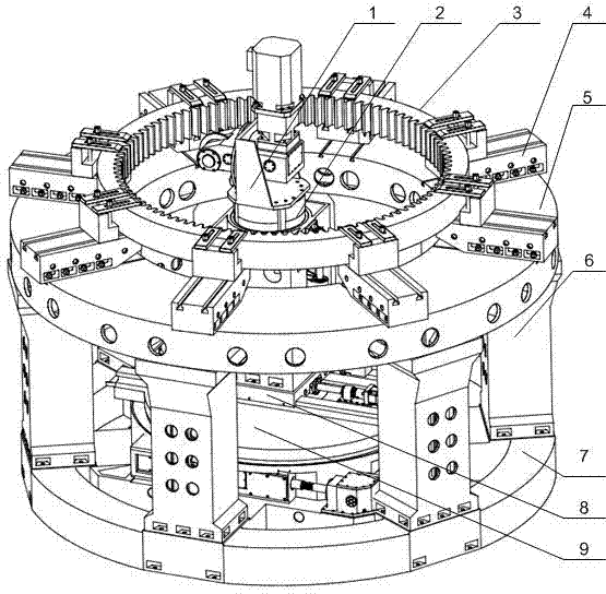
图1为本实用新型安装有工件的总体结构示意图; Fig. 1 is the overall structure schematic diagram that the utility model is installed with workpiece;
图2为本实用新型回转导轨部件的结构示意图; Fig. 2 is a schematic structural view of the rotary guide rail components of the utility model;
图3为本实用新型回转导轨部件沿蜗杆轴所在平面的局部剖视图; Fig. 3 is a partial cross-sectional view of the rotary guide rail part of the utility model along the plane where the worm shaft is located;
图4为本实用新型立柱部件的结构示意图; Figure 4 is a structural schematic diagram of the column parts of the utility model;
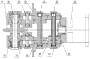
图5为本实用新型装有刀具的铣头部件的结构示意图; Fig. 5 is the structural schematic diagram of the milling head part that cutter is housed in the utility model;
图6为图5中的A-A剖视图。 Fig. 6 is a cross-sectional view of A-A in Fig. 5 .
图示标记:1、铣头支架; 2、 圆形升降立柱 ; 3、工件;4、 工件支承;5、 工件平台;6、平台支柱;7、整体式底座;8、 水平滑座;9、回转平台;10、伺服电机I;11、减速器I;12、 主动蜗杆;13、 中间传动装置;14、从动蜗杆;15、伺服电机II;16、 减速器 II;17、滚珠丝杠副II;18、 蜗轮;19、 消隙油缸;20、伺服电机III;21、 减速器III;22、滚珠丝杠副III;23、 丝母座 ; 24、立柱座;25、定向压块;26、定位衬套;27、主轴电机;28、减速器IV; 29、铣头箱体;30、刀具轴;31、刀具;32、 中间传动轴;33、传动齿轮。 Icon marks: 1. Milling head bracket; 2. Round lifting column; 3. Workpiece; 4. Workpiece support; 5. Workpiece platform; 6. Platform pillar; 7. Integral base; 8. Horizontal sliding seat; 9. Rotary platform; 10. Servo motor I; 11. Reducer I; 12. Driving worm; 13. Intermediate transmission device; 14. Driven worm; 15. Servo motor II; 16. Reducer II; 17. Ball screw pair II; 18. Worm gear; 19. Anti-backlash cylinder; 20. Servo motor III; 21. Reducer III; 22. Ball screw pair III; , Positioning bushing; 27, Spindle motor; 28, Reducer IV; 29, Milling head box; 30, Tool shaft; 31, Tool; 32, Intermediate transmission shaft; 33, Transmission gear. the
具体实施方式 Detailed ways
图中所示,具体实施方式如下: As shown in the figure, the specific implementation method is as follows:
一种内齿圈成型铣齿机,包括回转导轨部件、立柱部件、铣头部件、铣头支架1、开有中心孔的圆盘形工件平台5、平台支柱6和工件支承4,所述的回转导轨部件由上表面设置有导轨的回转平台9、水平滑座8、整体式底座7、以及为回转平台9和水平滑座8提供动力的驱动装置组成,回转平台9安装在整体式底座7上,回转平台9的回转中心与整体式底座7的中心重合,水平滑座8与回转平台9上表面的导轨相配合连接,立柱部件固定在水平滑座8上,铣头部件通过铣头支架1固定在立柱部件的上端,工件平台5固定在整体式底座7圆周分布的平台支柱6的上方,铣头部件穿过工件平台5上的中心孔,工件支承4径向滑动地设置在工件平台5上表面,工件支承4为复数个且沿工件平台5周向均匀分布。
A milling machine for forming an inner ring gear, comprising a rotary guide rail component, a column component, a milling head component, a milling head bracket 1, a disc-shaped
所述的驱动装置采用伺服电机I10通过减速器I11驱动蜗轮蜗杆副传动。 The drive device uses a servo motor I10 to drive a worm gear pair through a reducer I11. the
所述的立柱部件包括立柱座24、外圆周面上开设有导向槽的圆形升降立柱2、定位衬套26、定向压块25、滚珠丝杠副III22、丝母座23、减速器III21和伺服电机III20,圆形升降立柱2滑动安装在立柱座24中的定位衬套26内,立柱座24和定位衬套26的侧壁上开设有定位孔,定向压块25固定在定位孔内,并且与圆形升降立柱2上的导向槽配合设置,伺服电机III20固定在立柱座24上,并通过减速器III21带动滚珠丝杠副III22转动,滚珠丝杠副III22带动固定在圆形升降立柱2上的丝母座23运动。
The column components include a
所述的铣头部件包括铣头箱体29、刀具31、刀具轴30、减速器IV28、主轴电机27、以及由多个中间传动轴32和多个传动齿轮33组成的传动机构,所述的主轴电机27通过减速器IV28带动传动机构,传动机构驱动刀具轴30带动刀具31工作。
Described milling head part comprises milling
所述的铣头支架1的中心设有回转中心孔,铣头部件安装在回转中心孔内。 The center of the milling head support 1 is provided with a rotary center hole, and the milling head components are installed in the rotary center hole. the
所述的水平滑座8由其底部连接的滚珠丝杠副II17驱动沿所述导轨滑动,滚珠丝杠副II17由伺服电机II15带动的减速器II16驱动。
The horizontal sliding
所述的蜗轮蜗杆副包括安装在整体式底座7上的主动蜗杆12、从动蜗杆14、蜗轮18、锥齿轮组和消隙油缸19,蜗轮18安装在回转平台9下部,其旋转轴线与回转平台9的回转轴线重合,主动蜗杆12和从动蜗杆14均与蜗轮啮合,主动蜗杆12的一端通过锥齿轮组与从动蜗杆14的一端啮合,从动蜗杆14的另一端连接有消隙油缸19,主动蜗杆12的另一端与减速器I11的输出轴连接。
The worm gear pair includes a driving
所述的工件支承4上设置有用于固定工件的夹具。 The workpiece support 4 is provided with clamps for fixing the workpiece. the
如图1所示为一种数控内齿圈成型铣齿机,包括回转导轨部件、立柱部件、铣头部件、铣头支架1、工件平台5、平台支柱6、工件支承4。立柱部件固定于回转导轨部件的水平滑座8上,根据要加工工件直径的大小,沿着导轨在X方向移动。铣头部件通过铣头安装支架1固定于升降立柱部件的圆形升降立柱2的顶部,随着圆形升降立柱2的升降沿Y向运动。铣头部件可以在铣头支架1的安装孔内回转,加工斜齿时铣头部件根据工件螺旋角的大小调整其回转角度。回转导轨部件的回转导轨平台9带着立柱部件、铣头部件绕着其回转中心回转,完成分齿运动。工件平台5通过平台支柱6和回转导轨部件的整体式底座7固连为一体。工件平台5上面安装工件支承4,根据工件3规格的不同可以选用长度不同的工件支承4,并通过夹具将工件固定在工件支承4上,工件支承4可以沿工件平台5的径向移动。
As shown in Fig. 1, it is a kind of numerical control internal ring gear forming gear milling machine, including rotary guide rail parts, column parts, milling head parts, milling head support 1,
如图2、图3所示,回转导轨部件包括整体式底座7、回转平台9、主蜗轮蜗杆12、从蜗轮蜗杆14、蜗轮18、消隙油缸19、中间传动装置13、水平滑座8、滚珠丝杆副II17、减速器II16和伺服电机II15。整体式底座7外部六个均布的精加工面用于安装平台支柱6,整体式底座7的内部设有圆形导轨,用于支承回转导轨平台9。回转导轨平台9和整体式底座7内部的圆形导轨同心,二者通过滚动轴承装置或者静压轴承装置连接。主蜗轮蜗杆12和从蜗轮蜗杆14安装于整体式底座7,主蜗轮蜗杆12和从动蜗轮蜗杆14共用一个蜗轮18,该蜗轮安装于回转平台9的下部,并和其同轴。从蜗轮蜗杆14的另外一端装有消隙油缸19。伺服电机I10通过减速器I11和主蜗轮蜗杆12连接。水平滑座8安装于回转平台9的导轨上,伺服电机II15、减速器II16、滚珠丝杆副II17安装于回转平台9上。
As shown in Figure 2 and Figure 3, the rotary guide rail components include an
如图4所示,立柱部件包括立柱座24、圆形升降立柱2、定位衬套26、定向压块25、滚珠丝杠副III22、丝母座23、减速器III21、伺服电机III20。定位衬套26安装于立柱座24的内部,圆形升降立柱2安装于定位衬套26内部,二者同轴。为了增加刚度,圆形升降立柱2设计成双层结构,四周加工有导向面即为两个垂直面组成的导向槽。定向压块25固定于立柱座侧向凹槽内,和圆形升降立柱2的导向面配合。所述滚珠丝杠副III22的丝杠安装在立柱座侧面,滚珠丝杠副III22的丝母通过丝母座23和圆形升降立柱2连接。伺服电机III20通过减速器III21和滚珠丝杠副III22连接。
As shown in Figure 4, the column components include a
如图5、图6所示,铣头部件包括铣头箱体29、刀具轴30、中间传动轴32、传动齿轮33、减速器IV28、主轴电机27。刀具轴30、中间传动轴32、多个传动齿轮33安装于铣头箱体29内部,主轴电机27通过减速器IV28安装于铣头箱体29上部,刀具31安装于刀具轴30上。该实施例中的电机动力是通过两条传动链传递到刀具轴的。
As shown in FIG. 5 and FIG. 6 , the milling head components include a
以上对本实用新型的一个实施例进行了详细说明,但所述内容仅为本实用新型的较佳实施例,不能被认为用于限定本实用新型的实施范围。凡依本实用新型申请范围所做的均等变化与改进等,均应仍属于本实用新型的专利涵盖范围之内。 An embodiment of the present utility model has been described in detail above, but the content described is only a preferred embodiment of the present utility model, and cannot be considered as limiting the implementation scope of the present utility model. All equal changes and improvements made according to the application scope of the utility model should still belong to the scope covered by the patent of the utility model. the
Claims (8)
Priority Applications (1)
| Application Number | Priority Date | Filing Date | Title |
|---|---|---|---|
| CN201320473245.7U CN203390326U (en) | 2013-08-05 | 2013-08-05 | Forming gear milling machine for inner gear rings |
Applications Claiming Priority (1)
| Application Number | Priority Date | Filing Date | Title |
|---|---|---|---|
| CN201320473245.7U CN203390326U (en) | 2013-08-05 | 2013-08-05 | Forming gear milling machine for inner gear rings |
Publications (1)
| Publication Number | Publication Date |
|---|---|
| CN203390326U true CN203390326U (en) | 2014-01-15 |
Family
ID=49901888
Family Applications (1)
| Application Number | Title | Priority Date | Filing Date |
|---|---|---|---|
| CN201320473245.7U Expired - Lifetime CN203390326U (en) | 2013-08-05 | 2013-08-05 | Forming gear milling machine for inner gear rings |
Country Status (1)
| Country | Link |
|---|---|
| CN (1) | CN203390326U (en) |
Cited By (6)
| Publication number | Priority date | Publication date | Assignee | Title |
|---|---|---|---|---|
| CN103433568A (en) * | 2013-08-05 | 2013-12-11 | 河南科技大学 | Gear milling machine for forming inner gear ring |
| CN103878646A (en) * | 2014-03-12 | 2014-06-25 | 滕天阳 | Built-in machine tool |
| CN103962651A (en) * | 2014-04-30 | 2014-08-06 | 齐重数控装备股份有限公司 | Method for adjusting alignment accuracy of heavy vertical gear milling machine tool |
| CN109926655A (en) * | 2019-04-24 | 2019-06-25 | 沪东重机有限公司 | A kind of simple pneumatic crankshaft reaming device |
| CN111390297A (en) * | 2020-04-18 | 2020-07-10 | 无锡易通精密机械股份有限公司 | Copying cutting equipment and machining process for bearing gear ring insection |
| CN111843559A (en) * | 2020-09-08 | 2020-10-30 | 崔福才 | Positioning tool for radially drilling inner gear ring |
-
2013
- 2013-08-05 CN CN201320473245.7U patent/CN203390326U/en not_active Expired - Lifetime
Cited By (12)
| Publication number | Priority date | Publication date | Assignee | Title |
|---|---|---|---|---|
| CN103433568A (en) * | 2013-08-05 | 2013-12-11 | 河南科技大学 | Gear milling machine for forming inner gear ring |
| CN103878646A (en) * | 2014-03-12 | 2014-06-25 | 滕天阳 | Built-in machine tool |
| CN105252347A (en) * | 2014-03-12 | 2016-01-20 | 滕天阳 | built-in machine tool |
| CN105382554A (en) * | 2014-03-12 | 2016-03-09 | 滕天阳 | Built-in machine tool |
| CN103878646B (en) * | 2014-03-12 | 2016-07-06 | 滕天阳 | built-in machine tool |
| CN105252347B (en) * | 2014-03-12 | 2017-04-12 | 滕天阳 | Built-in machine tool |
| CN103962651A (en) * | 2014-04-30 | 2014-08-06 | 齐重数控装备股份有限公司 | Method for adjusting alignment accuracy of heavy vertical gear milling machine tool |
| CN109926655A (en) * | 2019-04-24 | 2019-06-25 | 沪东重机有限公司 | A kind of simple pneumatic crankshaft reaming device |
| CN111390297A (en) * | 2020-04-18 | 2020-07-10 | 无锡易通精密机械股份有限公司 | Copying cutting equipment and machining process for bearing gear ring insection |
| CN111390297B (en) * | 2020-04-18 | 2024-03-26 | 无锡易通精密机械股份有限公司 | Copying cutting equipment and machining process for gear ring insection of bearing |
| CN111843559A (en) * | 2020-09-08 | 2020-10-30 | 崔福才 | Positioning tool for radially drilling inner gear ring |
| CN111843559B (en) * | 2020-09-08 | 2021-12-14 | 江阴市万众精密机械有限公司 | Positioning tool for radially drilling inner gear ring |
Similar Documents
| Publication | Publication Date | Title |
|---|---|---|
| CN103433568B (en) | A milling machine for forming inner ring gear | |
| CN205218598U (en) | Brill of adjustable inclination and circumference graduation, reaming clamping device | |
| CN201455338U (en) | Double-column vertical digital controlled drill | |
| CN202411844U (en) | Rotary table mechanism for combined boring and milling machine tool of gantry drill | |
| CN103143789B (en) | A kind of gear cutting machine | |
| CN101829930B (en) | Engine cylinder head numerical control machine for floating ship | |
| CN202037476U (en) | Large-scale numerical control gear cutting machine | |
| CN201950299U (en) | Numerical control high precision static pressure rotating table | |
| CN102773719A (en) | Rotary table for numerical control floor type boring miller | |
| CN103481069A (en) | Rotary workbench and upright type turning and milling composite machine tool | |
| CN203184769U (en) | Gear cutting machine | |
| CN103273425A (en) | CBN grinding wheel track finishing device | |
| CN104476216B (en) | Heavy type numerical control floor type boring and milling machine heavy-loaded precision rotary table | |
| CN102357805A (en) | Rotating operating platform | |
| CN202655913U (en) | Rotary type workbench and vertical type turn milling compound machine tool | |
| CN205309801U (en) | Numerically -controlled rotary workbench | |
| CN204366433U (en) | Heavy type numerical control floor type boring and milling machine heavy-loaded precision rotary table | |
| CN203665074U (en) | Main shaft lifting numerical control turning drilling and milling composite machining machine tool | |
| CN103406768A (en) | High-precision vertical workbench base hydrostatic sealing structure | |
| CN202861549U (en) | Numerically-controlled gear hobbing machine | |
| CN210361982U (en) | Rotary workbench and vertical engraving machine | |
| CN201871947U (en) | Large precision numerically-controlled rotary worktable | |
| CN203779130U (en) | Anti-backlash and static pressure full closed-loop working platform provided double worms | |
| CN202539710U (en) | High-speed gear milling machine special for super-huge type slewing bearing | |
| CN219925969U (en) | Numerical control rotary table with hydrostatic gear indexing |
Legal Events
| Date | Code | Title | Description |
|---|---|---|---|
| C14 | Grant of patent or utility model | ||
| GR01 | Patent grant | ||
| AV01 | Patent right actively abandoned |
Granted publication date: 20140115 Effective date of abandoning: 20150909 |
|
| RGAV | Abandon patent right to avoid regrant |