CN203387058U - Low-voltage reactive power compensation cabinet - Google Patents
Low-voltage reactive power compensation cabinet Download PDFInfo
- Publication number
- CN203387058U CN203387058U CN201320460552.1U CN201320460552U CN203387058U CN 203387058 U CN203387058 U CN 203387058U CN 201320460552 U CN201320460552 U CN 201320460552U CN 203387058 U CN203387058 U CN 203387058U
- Authority
- CN
- China
- Prior art keywords
- cabinet
- switch
- described cabinet
- door
- voltage reactive
- Prior art date
- Legal status (The legal status is an assumption and is not a legal conclusion. Google has not performed a legal analysis and makes no representation as to the accuracy of the status listed.)
- Expired - Fee Related
Links
Images
Classifications
-
- Y—GENERAL TAGGING OF NEW TECHNOLOGICAL DEVELOPMENTS; GENERAL TAGGING OF CROSS-SECTIONAL TECHNOLOGIES SPANNING OVER SEVERAL SECTIONS OF THE IPC; TECHNICAL SUBJECTS COVERED BY FORMER USPC CROSS-REFERENCE ART COLLECTIONS [XRACs] AND DIGESTS
- Y02—TECHNOLOGIES OR APPLICATIONS FOR MITIGATION OR ADAPTATION AGAINST CLIMATE CHANGE
- Y02E—REDUCTION OF GREENHOUSE GAS [GHG] EMISSIONS, RELATED TO ENERGY GENERATION, TRANSMISSION OR DISTRIBUTION
- Y02E40/00—Technologies for an efficient electrical power generation, transmission or distribution
- Y02E40/30—Reactive power compensation
Abstract
The utility model discloses a low-voltage reactive power compensation cabinet which comprises a cabinet body, cabinet doors, a busbar, a knife-shaped isolator, a transformer, a zero bar, an earthing bar, a circuit breaker, a capacitor, a reactor, an isolating switch, a switching switch, a fuse, a controller, an ammeter, a voltmeter and a change-over switch, wherein the cabinet doors are installed on the obverse side and the reverse side of the cabinet body respectively, the busbar, the knife-shaped isolator, the transformer, the zero bar, the earthing bar, the circuit breaker, the capacitor, the reactor, the isolating switch, the switching switch and the fuse are installed inside the cabinet body, the controller, the ammeter, the voltmeter and the change-over switch are arranged on the cabinet doors, the switching switch is arranged to be a combination switch, and the combination switch is arranged between the capacitor and the fuse. According to the utility model, the combination switch combines advantages of small power consumption in operation of an AC contact and zero-crossing of a solid-state relay, i.e., a silicon controlled rectifier switch, thereby not only suppressing inrush current and avoiding arcing, but also being low in power consumption; and then the service life of the power compensation cabinet is enabled to be prolonged, the structure is reasonable, and the reliability is high.
Description
Technical field
The utility model relates to a kind of compensating cabinet, relates in particular to a kind of low voltage reactive compensation cabinet.
Background technology
The effect that reactive power compensation device is born in electric power system is the power factor that improves electrical network, reduces the loss of supply transformer and conveying circuit, and power supplying efficiency is provided, and improves the power supply environment; So reactive power compensation device is in an indispensable very important status in power supply system.Reasonably select reactive power compensation device, can accomplish to reduce to greatest extent the loss of supply network, in the change electric power system, reactive power is mobile, thereby improves the voltage levvl of electric power system, reduce via net loss and the dynamic property of improving electric power system, power grid quality is provided.Otherwise, as selected or improper use, may cause the problems such as electric power system voltage fluctuation, harmonic wave increase.
In the prior art, fling-cut switch in low voltage reactive compensation cabinet generally adopts A.C. contactor or solid-state relay (being thyristor switch), but use A.C. contactor to have problem: when A.C. contactor can produce surge current when dropping into or excise, the surge current maximum is possible surpass 100 times of capacitor rated current, surge current not only can produce disadvantageous interference to electrical network, A.C. contactor is easily produced to electric arc, and then easy scaling loss contact, and the inefficacy of surge current meeting speed-up condenser, reduce the useful life of capacitor, even blast, its useful life is short, poor reliability, the problem of using solid-state relay (being thyristor switch) to exist is: solid-state relay (being thyristor switch) be take controllable silicon as core, when the energising operation, the controlled silicon conducting voltage drop is about the 1V left and right, loss is very large, and (compensation arrangement of rated capacity 100Kvar of take is example, every phase rated current is about 145A, the specified conduction loss of controllable silicon is 145 * 1 * 3=435W), so owing to there being large power consumption to need heat radiation to avoid the thermal breakdown of PN knot, just need the radiator that usable floor area is very large in order to lower the temperature, even need fan to carry out forced ventilation, controllable silicon is very responsive to voltage change ratio (dv/dt) in addition, the situation that runs into the voltage jumps such as switching overvoltage and thunderbolt is easy to mislead and the damage of being shoved, even it is also of no avail that lightning arrester is installed, because lightning arrester can only deboost peak value, can not reduce voltage change ratio, so solid-state relay (being thyristor switch) complex structure, volume is large, loss is large, cost is high, poor reliability.
The utility model content
For this reason, technical problem to be solved in the utility model is the fling-cut switch used in low voltage reactive compensation cabinet of the prior art, or useful life is short, or complex structure, loss is large, cost is high, and poor reliability; And then improve a kind of long service life, rational in infrastructure, and the strong low voltage reactive compensation cabinet of reliability.
For solving the problems of the technologies described above, a kind of low voltage reactive compensation cabinet of the present utility model, it comprises cabinet, be located at described cabinet just, the back of the body two sides the cabinet door, and be arranged on busbar, knife-shaped isolator, instrument transformer, zero-emission, earthing bar, circuit breaker, capacitor, reactor, isolating switch, fling-cut switch, the fuse of described cabinet inside and be located at controller, ammeter, voltmeter, the change over switch on described cabinet door, described fling-cut switch is made as combination switch, and described combination switch is located between described capacitor and described fuse.
The front and back of described cabinet all is provided with two described cabinet doors, described cabinet door adopts door-hinge to be connected with described cabinet, described door-hinge is that stainless steel is made, and described cabinet and described cabinet door adopt the thick corrosion resistant plate of 1.0mm to make, and described bottom of cabinet bulk forms lower entrance hole and lower wire hole.
The outer surface of described cabinet and described cabinet door is provided with the coat for the protection of described cabinet and described cabinet door.
The insulated conductor connected for auxiliary circuit in described cabinet is tied up bunchy, and is fixedly linked with described cabinet.
Described circuit breaker is made as moulded case circuit breaker, and described controller is made as reactive power self-compensating controlling device.
Described isolating switch is made as open type knife switch.
Technique scheme of the present utility model has the following advantages compared to existing technology: in the utility model, described fling-cut switch is made as combination switch, and described combination switch is located between described capacitor and described fuse; Described combination switch combines the advantage of little and solid-state relay (the being thyristor switch) operating passing zero of performance A.C. contactor operation power consumption, and it has not only suppressed to shove, avoided arcing, and power consumption is lower; And then make this compensating cabinet long service life, rational in infrastructure, and reliability is strong.
The accompanying drawing explanation
For content of the present utility model is more likely to be clearly understood, below according to specific embodiment of the utility model also by reference to the accompanying drawings, the utility model is described in further detail, wherein
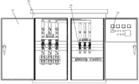
Fig. 1 is that low voltage reactive compensation cabinet described in the utility model is opened front cabinet structural representation behind the door;
Fig. 2 is that low voltage reactive compensation cabinet described in the utility model is opened back side cabinet structural representation behind the door;
In figure, Reference numeral is expressed as: the 11-cabinet; 12-cabinet door; The 13-fling-cut switch; The 14-circuit breaker; The 15-controller; The 16-isolating switch.
Embodiment
Below with reference to accompanying drawing, and use following examples to be further elaborated the utility model.
As shown in Figure 1-2, the described a kind of low voltage reactive compensation cabinet of the present embodiment, it comprises cabinet 11, be located at described cabinet 11 just, the cabinet door 12 on back of the body two sides, and be arranged on busbar, knife-shaped isolator, instrument transformer, zero-emission, earthing bar, circuit breaker 14, capacitor, reactor, isolating switch 16, fling-cut switch 13, the fuse of described cabinet 11 inside and be located at controller 15, ammeter, voltmeter, the change over switch on described cabinet door 12; Described fling-cut switch 13 is made as combination switch, and described combination switch is located between described capacitor and described fuse.In the present embodiment, described combination switch combines the advantage of little and solid-state relay (the being thyristor switch) operating passing zero of performance A.C. contactor operation power consumption, and it has not only suppressed to shove, avoided arcing, and power consumption is lower; And then make this compensating cabinet long service life, rational in infrastructure, and reliability is strong.
In the present embodiment, the front and back of described cabinet 11 all is provided with two described cabinet doors 12, described cabinet door 12 adopts door-hinge to be connected with described cabinet 11, described door-hinge is that stainless steel is made, described cabinet 11 and described cabinet door 12 adopt the thick corrosion resistant plate of 1.0mm to make, and described cabinet 11 bottoms form lower entrance hole and lower wire hole; The outer surface of described cabinet 11 and described cabinet door 12 is provided with the coat for the protection of described cabinet 11 and described cabinet door 12; Thereby make the described low-voltage reactive compensator of the present embodiment there is good planarization and corrosion resistance, make it can be applicable to open air.
On the basis of above-described embodiment, the insulated conductor connected for auxiliary circuit in described cabinet 11 is tied up bunchy, and is fixedly linked with described cabinet 11; Thereby it is chaotic to avoid described cabinet 1111 inside conductors to disperse, and is convenient to detect and maintenance.
Described circuit breaker 14 is made as moulded case circuit breaker, and described controller 15 is made as reactive power self-compensating controlling device.Described isolating switch 16 is made as open type knife switch.
Obviously, above-described embodiment is only for example clearly is described, and is not the restriction to execution mode.For those of ordinary skill in the field, can also make other changes in different forms on the basis of the above description.Here exhaustive without also giving all execution modes.And the apparent variation of being extended out thus or change are still among the protection range in the invention.
Claims (6)
1. a low voltage reactive compensation cabinet, it comprises cabinet (11), just be located at described cabinet (11), the cabinet door (12) on back of the body two sides, and the busbar that is arranged on described cabinet (11) inside, knife-shaped isolator, instrument transformer, zero-emission, earthing bar, circuit breaker (14), capacitor, reactor, isolating switch (16), fling-cut switch (13), fuse and be located at the controller (15) on described cabinet door (12), ammeter, voltmeter, change over switch, it is characterized in that: described fling-cut switch (13) is made as combination switch, described combination switch is located between described capacitor and described fuse.
2. low voltage reactive compensation cabinet according to claim 1, it is characterized in that: the front and back of described cabinet (11) all is provided with two described cabinet doors (12), described cabinet door (12) adopts door-hinge to be connected with described cabinet (11), described door-hinge is that stainless steel is made, described cabinet (11) and described cabinet door (12) adopt the thick corrosion resistant plate of 1.0mm to make, and described cabinet (11) bottom forms lower entrance hole and lower wire hole.
3. low voltage reactive compensation cabinet according to claim 2, it is characterized in that: the outer surface of described cabinet (11) and described cabinet door (12) is provided with the coat for the protection of described cabinet (11) and described cabinet door (12).
4. low voltage reactive compensation cabinet according to claim 1, is characterized in that: tie up bunchy for the insulated conductor of auxiliary circuit connection in described cabinet (11), and be fixedly linked with described cabinet (11).
5. according to the arbitrary described low voltage reactive compensation cabinet of claim 1-4, it is characterized in that: described circuit breaker (14) is made as moulded case circuit breaker, and described controller (15) is made as reactive power self-compensating controlling device.
6. according to the arbitrary described low voltage reactive compensation cabinet of claim 1-4, it is characterized in that: described isolating switch (16) is made as open type knife switch.
Priority Applications (1)
| Application Number | Priority Date | Filing Date | Title |
|---|---|---|---|
| CN201320460552.1U CN203387058U (en) | 2013-07-31 | 2013-07-31 | Low-voltage reactive power compensation cabinet |
Applications Claiming Priority (1)
| Application Number | Priority Date | Filing Date | Title |
|---|---|---|---|
| CN201320460552.1U CN203387058U (en) | 2013-07-31 | 2013-07-31 | Low-voltage reactive power compensation cabinet |
Publications (1)
| Publication Number | Publication Date |
|---|---|
| CN203387058U true CN203387058U (en) | 2014-01-08 |
Family
ID=49875510
Family Applications (1)
| Application Number | Title | Priority Date | Filing Date |
|---|---|---|---|
| CN201320460552.1U Expired - Fee Related CN203387058U (en) | 2013-07-31 | 2013-07-31 | Low-voltage reactive power compensation cabinet |
Country Status (1)
| Country | Link |
|---|---|
| CN (1) | CN203387058U (en) |
Cited By (1)
| Publication number | Priority date | Publication date | Assignee | Title |
|---|---|---|---|---|
| CN115377840A (en) * | 2022-10-18 | 2022-11-22 | 湖南新泉电气有限公司 | Electric energy metering box convenient to electric power construction operation |
-
2013
- 2013-07-31 CN CN201320460552.1U patent/CN203387058U/en not_active Expired - Fee Related
Cited By (1)
| Publication number | Priority date | Publication date | Assignee | Title |
|---|---|---|---|---|
| CN115377840A (en) * | 2022-10-18 | 2022-11-22 | 湖南新泉电气有限公司 | Electric energy metering box convenient to electric power construction operation |
Similar Documents
| Publication | Publication Date | Title |
|---|---|---|
| CN203387058U (en) | Low-voltage reactive power compensation cabinet | |
| Iyer et al. | DC distribution systems for homes | |
| CN102290805A (en) | Electric arc grounding overvoltage limiting device applied to medium-voltage distribution system | |
| CN202564798U (en) | Intelligent harmonic and arc extinction switch cabinet | |
| CN201853820U (en) | Miniature busbar connecting structure at top of metal armoured middle switch cabinet | |
| CN202535050U (en) | Combined type grounding system for reactance and resistor in power distribution network | |
| CN103199441B (en) | For the main transformer plug-in type switch of transformer station | |
| CN204156531U (en) | High-voltage generator system power factor compensation arrangement | |
| CN110557030A (en) | Design method of cascaded high-voltage frequency converter for high-altitude area | |
| CN203242919U (en) | Main transformer plug-in type switch for transformer substation | |
| CN204230887U (en) | A kind of nonlinear resistance type resonance eliminator | |
| CN204304424U (en) | A kind of single-phase earthing superpotential transfer restraint device | |
| CN204258314U (en) | For the high reliability switching circuit of the parallel power condenser reactive power compensator | |
| CN203326377U (en) | Low-voltage reactive compensation cabinet | |
| CN203387193U (en) | Low-voltage reactive power compensation cabinet | |
| CN202906479U (en) | Power-capacitor switching apparatus | |
| CN203632068U (en) | High-voltage SF6 phase angle position control switching circuit breaker prefabricated cabin | |
| CN202524006U (en) | High-voltage metal-enclosed switchgear | |
| CN204205307U (en) | A kind of plateau type armored cabinet and PT dolly supporting with it | |
| CN219833764U (en) | Power grid fault metallic grounding transfer device | |
| CN203397888U (en) | 35kV current transformer | |
| CN203135434U (en) | Neutral point virtual grounding device | |
| CN203312821U (en) | Dynamic and continuous reactive power compensation device of low-voltage distribution system | |
| CN102332722A (en) | Matched filtering compensation energy-saving complete device for rectifying transformer | |
| CN203631408U (en) | Indoor high-voltage alternating-current vacuum generator circuit breaker |
Legal Events
| Date | Code | Title | Description |
|---|---|---|---|
| C14 | Grant of patent or utility model | ||
| GR01 | Patent grant | ||
| CF01 | Termination of patent right due to non-payment of annual fee |
Granted publication date: 20140108 Termination date: 20140731 |
|
| EXPY | Termination of patent right or utility model |