CN203379765U - Dust purification device - Google Patents
Dust purification device Download PDFInfo
- Publication number
- CN203379765U CN203379765U CN201320466598.4U CN201320466598U CN203379765U CN 203379765 U CN203379765 U CN 203379765U CN 201320466598 U CN201320466598 U CN 201320466598U CN 203379765 U CN203379765 U CN 203379765U
- Authority
- CN
- China
- Prior art keywords
- dust
- tank
- teeter chamber
- water
- purification
- Prior art date
- Legal status (The legal status is an assumption and is not a legal conclusion. Google has not performed a legal analysis and makes no representation as to the accuracy of the status listed.)
- Expired - Fee Related
Links
Images
Abstract
The utility model relates to a dust purification device for preventing and controlling environment pollution. The device comprises a blower, a purification tank, a water pipe and spray nozzles, wherein the air outlet pipe of the blower is tangent with the inner wall of a dust collection drum. The device is characterized in that the bottom of the dust collection drum is communicated with a stirring chamber through a feed tank, and an exhaust pipe is arranged on the top of the blower; the exhaust pipe extends to the bottom of the purification tank; the spray nozzles are uniformly distributed above the stirring chamber and are connected with the purification tank through a water gauge, the water pipe and a water pump in sequence; a helical blade is arranged in the stirring chamber, a discharge port is formed in the bottom of the tail end of the stirring chamber, and a pluggable baffle is arranged between the discharge port and the stirring chamber. The dust purification chamber is convenient to operate, saves time and labor, does not need to frequently clean internal components, can be used for purifying dust completely, and can remarkably reduce the purification time.
Description
Technical field
The utility model relates to a kind of for preventing and treating the powder purification apparatus of environmental pollution.
Background technology
The dust pelletizing system of chilli food processing industry generally adopts air-introduced machine that dust is caused to filter mantle, regathers secondary filter in fabric dust collecting sleeve, and its major defect is that dust can see through the dust collecting sleeve infiltration external world, pollutes; Also must periodic cleaning filter mantle and dust collecting sleeve, use very inconvenient, and dust topple over and processing is easy to cause dust from flying, cause secondary pollution.
Also adopted the spray cleaning technology in prior art, by spraying and spray water adsorbing powder dust on the globule and converging into current, enter the clarifier-tank precipitation through mozzle and filter screen, the dust from flying that this technology has caused while effectively having avoided the cleaning dust collecting sleeve, its major defect is that the mud that dust and water form easily adheres to and is deposited on mozzle inwall and filter screen, and it is high that filter screen easily stops up, clears up frequency, and to only have two ends to have uncovered because of mozzle, must could clear up inwall by instrument, waste time and energy; In addition, the clarifier-tank sedimentation time is long, and because the dust molecule quality produced in the capsicum process is light and be difficult for being melted into water, can not all be adsorbed by the globule, the dust that is not adsorbed of part can be with gas discharging in atmosphere or swim in the clarifier-tank water surface and do not sink, meet wind and again fly upward, purify still not thorough.
The utility model content
The utility model, for addressing the above problem, provides a kind of powder purification apparatus.
For achieving the above object, the technical scheme that the utility model adopts is as follows.
A kind of powder purification apparatus, comprise air blast, clarifier-tank, water pipe, spray nozzle, the discharge pipe of air blast is tangent with the inwall of the cylinder that gathers dust, and it is characterized in that: the cylinder bottom of gathering dust is communicated with teeter chamber by material feeding box, blast pipe is arranged at a top of gathering dust, and blast pipe reaches the clarifier-tank bottom.
Top, aforementioned teeter chamber is evenly equipped with spray nozzle, and spray nozzle is connected with clarifier-tank by water meter, water pipe, water pump successively.
In aforementioned teeter chamber, helical blade is arranged, the central shaft of helical blade is connected with motor by belt.
Discharging opening is arranged at the bottom of aforementioned teeter chamber end, and the plate washer that can pull and push is arranged between discharging opening and teeter chamber.
Adopt technique scheme, because the discharge pipe of air blast is tangent with the inwall of the cylinder that gathers dust, the interior air-flow of cylinder that makes to gather dust carries dust and rotates, dust granules separates and gets rid of on an inwall that gathering dust under the effect of centrifugal force from air-flow, then air-flow enters in the water of clarifier-tank by blast pipe, residual dust in the water filtration air-flow, the air-flow after purification enters atmosphere with bubble; Simultaneously, gather dust the dust of an inwall because gravitate is deposited to, gather dust the cylinder bottom material feeding box and enter teeter chamber; Helical blade is separated into a plurality of capacitors by teeter chamber, a plurality of chambers are isolated in respectively different spaces by dust, dust number quantitative change in single chamber is little, more easily by spray nozzle, fully sprayed, after spray, dust stirs and moves to teeter chamber's end under the turn of helical blade, dust finally is stirred into walk, takes out out plate washer, and walk crashes into discharging opening.
By water meter, can observe spray to the water yield of teeter chamber, be convenient to open or close in time water pump, prevent from that dust is stirred to be diluted to mud juice.Pull and push plate washer, can control the dust mixing time, after stirring fully, take out out again plate washer.
The swirling eddy gathered dust in cylinder can realize the gathering dust automatically cleaning of an inwall; The spray nozzle of teeter chamber also can be realized simple automatically cleaning under Water Pressure, even a small amount of dirt is arranged, also can not stop up spray nozzle; The power transmission of helical blade is positioned at the outside, teeter chamber, does not therefore clear up inside, teeter chamber, also can not affect the helical blade normal operation.
Through gather dust a centrifugal dust-removing and diving, filter, thoroughly purifying and stive; Dust is integrated with water into walk in teeter chamber, has reduced the sedimentation time of clarifier-tank.Whole collection and purification process, substantially without personnel's physical demands, and the utility model is without the cleaning internals.
The utility model is easy and simple to handle, time saving and energy saving, and without often clearing up internals, not only dust purification is thorough, and can obviously reduce the clarification time.
The accompanying drawing explanation
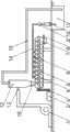
Shown in Fig. 1 is structural representation of the present utility model.
What in figure, indicate is labeled as: 1, air blast; 2, motor; 3, belt; 4, teeter chamber; 5, helical blade; 6, spray nozzle; 7, discharging opening; 8, plate washer; 9, water meter; 10, water pump; 11, clarifier-tank; 12, the cylinder that gathers dust; 13, discharge pipe; 14, water pipe; 15, blast pipe; 16, material feeding box.
The specific embodiment
Below in conjunction with drawings and Examples, the utility model is described in further detail.
As shown in Figure 1, the utility model comprises air blast (1), clarifier-tank (11), water pipe (14), spray nozzle (6), the discharge pipe (13) of air blast (1) is tangent with the inwall of the cylinder (12) that gathers dust, cylinder (12) bottom of gathering dust is communicated with teeter chamber (4) by material feeding box (16), blast pipe (15) is arranged at cylinder (12) top of gathering dust, and blast pipe (15) reaches clarifier-tank (11) bottom.Top, teeter chamber (4) is evenly equipped with spray nozzle (6), and spray nozzle (6) is connected with clarifier-tank (11) by water meter (9), water pipe (14), water pump (10) successively.Helical blade (5) is arranged in teeter chamber (4), and the central shaft of helical blade (5) is connected with motor (2) by belt (3).Discharging opening (7) is arranged at the bottom of teeter chamber (4) end, and the plate washer (8) that can pull and push is arranged between discharging opening (7) and teeter chamber (4).
Claims (2)
1. a powder purification apparatus, comprise air blast (1), clarifier-tank (11), water pipe (14), spray nozzle (6), the discharge pipe (13) of air blast (1) is tangent with the inwall of the cylinder (12) that gathers dust, it is characterized in that: cylinder (12) bottom of gathering dust is communicated with teeter chamber (4) by material feeding box (16), blast pipe (15) is arranged at cylinder (12) top of gathering dust, and blast pipe (15) reaches clarifier-tank (11) bottom; Top, teeter chamber (4) is evenly equipped with spray nozzle (6), and spray nozzle (6) is connected with clarifier-tank (11) by water meter (9), water pipe (14), water pump (10) successively.
2. a kind of powder purification apparatus according to claim 1 is characterized in that: helical blade (5) is arranged in teeter chamber (4), and the central shaft of helical blade (5) is connected with motor (2) by belt (3); Discharging opening (7) is arranged at the bottom of teeter chamber (4) end, and the plate washer (8) that can pull and push is arranged between discharging opening (7) and teeter chamber (4).
Priority Applications (1)
| Application Number | Priority Date | Filing Date | Title |
|---|---|---|---|
| CN201320466598.4U CN203379765U (en) | 2013-08-01 | 2013-08-01 | Dust purification device |
Applications Claiming Priority (1)
| Application Number | Priority Date | Filing Date | Title |
|---|---|---|---|
| CN201320466598.4U CN203379765U (en) | 2013-08-01 | 2013-08-01 | Dust purification device |
Publications (1)
| Publication Number | Publication Date |
|---|---|
| CN203379765U true CN203379765U (en) | 2014-01-08 |
Family
ID=49868298
Family Applications (1)
| Application Number | Title | Priority Date | Filing Date |
|---|---|---|---|
| CN201320466598.4U Expired - Fee Related CN203379765U (en) | 2013-08-01 | 2013-08-01 | Dust purification device |
Country Status (1)
| Country | Link |
|---|---|
| CN (1) | CN203379765U (en) |
Cited By (2)
| Publication number | Priority date | Publication date | Assignee | Title |
|---|---|---|---|---|
| CN108032224A (en) * | 2017-10-26 | 2018-05-15 | 重庆纵翼机械制造有限公司 | Shaftless screw grinding dust removing device |
| CN108479363A (en) * | 2018-04-13 | 2018-09-04 | 宁波清智环保科技有限公司 | Environmentally friendly emission-control equipment |
-
2013
- 2013-08-01 CN CN201320466598.4U patent/CN203379765U/en not_active Expired - Fee Related
Cited By (2)
| Publication number | Priority date | Publication date | Assignee | Title |
|---|---|---|---|---|
| CN108032224A (en) * | 2017-10-26 | 2018-05-15 | 重庆纵翼机械制造有限公司 | Shaftless screw grinding dust removing device |
| CN108479363A (en) * | 2018-04-13 | 2018-09-04 | 宁波清智环保科技有限公司 | Environmentally friendly emission-control equipment |
Similar Documents
| Publication | Publication Date | Title |
|---|---|---|
| CN204107249U (en) | A kind of biomass fuel dust arrester | |
| CN204874120U (en) | Waste gas waste water that sprays paint integration processing system | |
| CN204724024U (en) | Wet smoke processor | |
| CN207237438U (en) | Bio-pharmaceuticals isolates and purifies filtration apparatus | |
| CN206715656U (en) | Industrial chemicals combustion tail gas processing unit | |
| CN105771516A (en) | Centrifugal gas way type gas purifier | |
| CN203379765U (en) | Dust purification device | |
| CN208526090U (en) | A kind of chemical industry tail gas processing unit | |
| CN108619843B (en) | Industrial waste gas desulfurization denitration dust collecting equipment | |
| CN208320333U (en) | A kind of easy building dust-extraction unit | |
| CN202346925U (en) | Powdery fertilizer dust-free production device | |
| CN105126552B (en) | A kind of screw concrete formula dedusting recovery system | |
| CN212119540U (en) | Petrochemical industry tail gas treatment facility of environmental protection | |
| CN204851793U (en) | Air purification ventilation blower | |
| CN109107762B (en) | A kind of dust-extraction unit and its dust removal method for processing dust for removing magnet | |
| CN203329480U (en) | Improved water purifier | |
| CN217015966U (en) | Pneumatic mixing cyclone tower suitable for flue gas treatment | |
| CN215916855U (en) | Dust arrester installation is used in water purification agent production convenient to clearance | |
| CN107537262A (en) | Spiral-flow type air cleaning system | |
| CN207445858U (en) | Spiral-flow type air cleaning system | |
| CN112843968A (en) | Solid-state flue gas treatment device for chemical experiment | |
| CN206351025U (en) | Closed high speed dispersor | |
| CN215962759U (en) | Cement production device capable of efficiently removing dust | |
| CN219272594U (en) | Chemical equipment with tail gas treatment device | |
| CN217092674U (en) | Coal dressing dust collector |
Legal Events
| Date | Code | Title | Description |
|---|---|---|---|
| C14 | Grant of patent or utility model | ||
| GR01 | Patent grant | ||
| CF01 | Termination of patent right due to non-payment of annual fee | ||
| CF01 | Termination of patent right due to non-payment of annual fee |
Granted publication date: 20140108 Termination date: 20160801 |