CN203376656U - Intelligent integrated control system for grain depot - Google Patents
Intelligent integrated control system for grain depot Download PDFInfo
- Publication number
- CN203376656U CN203376656U CN201320354861.0U CN201320354861U CN203376656U CN 203376656 U CN203376656 U CN 203376656U CN 201320354861 U CN201320354861 U CN 201320354861U CN 203376656 U CN203376656 U CN 203376656U
- Authority
- CN
- China
- Prior art keywords
- temperature
- humidity sensor
- optical fiber
- repeater
- router
- Prior art date
- Legal status (The legal status is an assumption and is not a legal conclusion. Google has not performed a legal analysis and makes no representation as to the accuracy of the status listed.)
- Withdrawn - After Issue
Links
- 238000004891 communication Methods 0.000 claims abstract description 95
- 239000013307 optical fiber Substances 0.000 claims abstract description 75
- 239000007789 gas Substances 0.000 claims abstract description 48
- 238000012544 monitoring process Methods 0.000 claims abstract description 21
- XYFCBTPGUUZFHI-UHFFFAOYSA-N Phosphine Chemical compound P XYFCBTPGUUZFHI-UHFFFAOYSA-N 0.000 claims abstract description 17
- 238000009423 ventilation Methods 0.000 claims abstract description 16
- 239000000835 fiber Substances 0.000 claims description 34
- IJGRMHOSHXDMSA-UHFFFAOYSA-N Atomic nitrogen Chemical compound N#N IJGRMHOSHXDMSA-UHFFFAOYSA-N 0.000 claims description 14
- CURLTUGMZLYLDI-UHFFFAOYSA-N Carbon dioxide Chemical compound O=C=O CURLTUGMZLYLDI-UHFFFAOYSA-N 0.000 claims description 14
- QVGXLLKOCUKJST-UHFFFAOYSA-N atomic oxygen Chemical compound [O] QVGXLLKOCUKJST-UHFFFAOYSA-N 0.000 claims description 7
- 239000001569 carbon dioxide Substances 0.000 claims description 7
- 229910002092 carbon dioxide Inorganic materials 0.000 claims description 7
- 229910052757 nitrogen Inorganic materials 0.000 claims description 7
- 239000001301 oxygen Substances 0.000 claims description 7
- 229910052760 oxygen Inorganic materials 0.000 claims description 7
- 238000007639 printing Methods 0.000 claims description 4
- 230000002159 abnormal effect Effects 0.000 abstract description 9
- 230000000694 effects Effects 0.000 abstract description 7
- 230000007797 corrosion Effects 0.000 abstract description 6
- 238000005260 corrosion Methods 0.000 abstract description 6
- 238000013461 design Methods 0.000 abstract description 5
- 238000001514 detection method Methods 0.000 abstract description 2
- 238000009529 body temperature measurement Methods 0.000 abstract 1
- 235000013339 cereals Nutrition 0.000 description 40
- 239000000523 sample Substances 0.000 description 28
- 238000000034 method Methods 0.000 description 25
- 230000006870 function Effects 0.000 description 8
- 238000012423 maintenance Methods 0.000 description 6
- 230000005540 biological transmission Effects 0.000 description 5
- 238000007405 data analysis Methods 0.000 description 5
- 230000007547 defect Effects 0.000 description 4
- 238000010586 diagram Methods 0.000 description 4
- 229910000073 phosphorus hydride Inorganic materials 0.000 description 4
- 238000012545 processing Methods 0.000 description 4
- 230000005856 abnormality Effects 0.000 description 3
- 230000032683 aging Effects 0.000 description 3
- 238000004458 analytical method Methods 0.000 description 3
- 238000013480 data collection Methods 0.000 description 3
- 238000005516 engineering process Methods 0.000 description 3
- 230000004044 response Effects 0.000 description 3
- 230000008054 signal transmission Effects 0.000 description 3
- 239000002253 acid Substances 0.000 description 2
- 238000012937 correction Methods 0.000 description 2
- 238000005265 energy consumption Methods 0.000 description 2
- 230000001105 regulatory effect Effects 0.000 description 2
- RYGMFSIKBFXOCR-UHFFFAOYSA-N Copper Chemical compound [Cu] RYGMFSIKBFXOCR-UHFFFAOYSA-N 0.000 description 1
- 230000009286 beneficial effect Effects 0.000 description 1
- 238000006243 chemical reaction Methods 0.000 description 1
- 238000010276 construction Methods 0.000 description 1
- 229910052802 copper Inorganic materials 0.000 description 1
- 239000010949 copper Substances 0.000 description 1
- 238000011161 development Methods 0.000 description 1
- 230000018109 developmental process Effects 0.000 description 1
- 230000005670 electromagnetic radiation Effects 0.000 description 1
- 239000002360 explosive Substances 0.000 description 1
- 238000009434 installation Methods 0.000 description 1
- 238000004519 manufacturing process Methods 0.000 description 1
- 230000035800 maturation Effects 0.000 description 1
- 238000005259 measurement Methods 0.000 description 1
- 239000002184 metal Substances 0.000 description 1
- 229910052751 metal Inorganic materials 0.000 description 1
- 230000006855 networking Effects 0.000 description 1
- 230000003287 optical effect Effects 0.000 description 1
- 230000008569 process Effects 0.000 description 1
- 238000005070 sampling Methods 0.000 description 1
- 238000012876 topography Methods 0.000 description 1
Images




Classifications
-
- Y—GENERAL TAGGING OF NEW TECHNOLOGICAL DEVELOPMENTS; GENERAL TAGGING OF CROSS-SECTIONAL TECHNOLOGIES SPANNING OVER SEVERAL SECTIONS OF THE IPC; TECHNICAL SUBJECTS COVERED BY FORMER USPC CROSS-REFERENCE ART COLLECTIONS [XRACs] AND DIGESTS
- Y02—TECHNOLOGIES OR APPLICATIONS FOR MITIGATION OR ADAPTATION AGAINST CLIMATE CHANGE
- Y02P—CLIMATE CHANGE MITIGATION TECHNOLOGIES IN THE PRODUCTION OR PROCESSING OF GOODS
- Y02P90/00—Enabling technologies with a potential contribution to greenhouse gas [GHG] emissions mitigation
- Y02P90/02—Total factory control, e.g. smart factories, flexible manufacturing systems [FMS] or integrated manufacturing systems [IMS]
Landscapes
- Arrangements For Transmission Of Measured Signals (AREA)
- Emergency Alarm Devices (AREA)
Abstract
The utility model relates to an intelligent integrated control system for a grain depot. The intelligent integrated control system comprises an upper computer that is connected with output terminals of a plurality of repeaters by a terminal receiver and a router successively. The repeaters are connected with out-cabin air humidity-temperature sensors, ventilation devices, LED screens and a plurality of optical fiber temperature-humidity sensor systems; and the input terminal of each optical fiber temperature-humidity sensor system is connected with an in-cabin air humidity-temperature sensor, a gas detector and a plurality of optical fiber temperature sensors. When the intelligent integrated control system is used, the optical fiber temperature-humidity sensor systems transmit information of grain temperature, air temperature and humidity, and gas information to upper-level equipment according to communication requirements; the upper computer carries out monitoring according to the received downstream data; and when an abnormal situation occurs, an alarm is sent out. On the basis of the design, the temperature measurement points are distributed widely; the positioning performance is high; grain temperature detection by electronic components can be eliminated; and the hydrogen phosphide corrosion-resistant performance is realized. Because of the wireless communication structure, grain situation can be monitored remotely; the monitoring effect and security are excellent; and the application range is wide.
Description
Technical field
The utility model relates to a kind of Grain Storage Control System, relates in particular to a kind of grain depot intelligent comprehensive control system, specifically is applicable to the monitoring effect and the security that fibre optic temperature sensor, wireless communication configuration are combined to improve grain depot.
Background technology
Grain reserves are important leverages of safeguarding national stability and development.It is the important step that prevents that grain from going rotten, guaranteeing the quality and deposit that cereal temperature detects.In grain temperature detector survey process, because grain is many, the silo volume is large, the temperature of diverse location is different, must carry out multimetering.
Traditional grain temperature supervisory system be take thermistor as temperature-sensing element (device), and adopt the wire communication structure more, there is following problem in it: 1. use the thermistor detecting temperature, need to compensate correction to each road sensor output signal 2. electric signal is arranged, use in silo and have potential safety hazard 3. electronic devices and components are easily aging, make moist, easily the even malfunctioning 4. rate of false alarm of wrong report is high, faults frequent, make troubles to construction and maintenance, maintenance cost height 5. wire communication causes circuit long, physical damage easily occurs, also electromagnetic interference (EMI) can occur simultaneously, affect the perishable electronic devices and components of phosphine gas that adopt when 6. the measured temperature precision fumigates, especially can corroding metal copper, make expensive device become disposable products.
Summary of the invention
The purpose of this utility model is to overcome the employing electronic devices and components detecting temperature existed in prior art, defect and the problem that adopts the wire communication structure, and a kind of grain depot intelligent comprehensive control system that adopts the fiber-optic probe temperature, adopts wireless communication configuration is provided.
For realizing above purpose, technical solution of the present utility model is: a kind of grain depot intelligent comprehensive control system, comprise host computer and a plurality of Temperature and Humidity Sensor System, an end of described Temperature and Humidity Sensor System is connected with monitoring system in storehouse, and the other end is connected with host computer;
Described grain depot intelligent comprehensive control system also comprises repeater, router and terminal receiver; In described storehouse, monitoring system comprises aerial temperature and humidity sensor in storehouse, gas detector and a plurality of fibre optic temperature sensor; Described Temperature and Humidity Sensor System is the optical fiber Temperature and Humidity Sensor System;
In described storehouse, the output terminal of aerial temperature and humidity sensor, gas detector, fibre optic temperature sensor is connected with the input end of optical fiber Temperature and Humidity Sensor System, the output terminal of optical fiber Temperature and Humidity Sensor System, storehouse outer air Temperature Humidity Sensor is connected with the input end of repeater, the output terminal of repeater is connected with the input end of ventilation equipment, LED screen, router, the output terminal of router is connected with host computer after terminal receiver, and is connected with warning system on terminal receiver.
The quantity of described optical fiber Temperature and Humidity Sensor System is 20 of 1 –, and the quantity of the corresponding fibre optic temperature sensor of each optical fiber Temperature and Humidity Sensor System is 256 of 1 –.
Described gas detector comprises carbon dioxide detector, hydrogen phosphide detector, oxygen sensor and nitrogen detector.
Described optical fiber Temperature and Humidity Sensor System, repeater, router, terminal receiver all adopt the STM32 microprocessor; Described optical fiber Temperature and Humidity Sensor System is arranged in silo, and repeater, LED screen, ventilation equipment all are arranged on the silo exterior wall, and terminal receiver, host computer are installed in duty room.
Described optical fiber Temperature and Humidity Sensor System is connected with repeater by 485 communication modules, repeater is connected with router by the Zigbee communication, router is connected with terminal receiver by the CAN bus, and terminal receiver is connected with host computer by the usb communication mode.
Described warning system comprises acoustic-optic alarm, automatically sends short message apparatus, automatic poking phone with mobile telephone device and fixed line warning device automatically; Be connected with real-time display device, printing device and memory device on described host computer.
The quantity of described repeater is a plurality of, and repeater is corresponding one by one with silo.
Compared with prior art, the beneficial effects of the utility model are:
1, be connected with a plurality of fibre optic temperature sensors on an optical fiber Temperature and Humidity Sensor System in the utility model grain depot intelligent comprehensive control system, be connected with a plurality of optical fiber Temperature and Humidity Sensor System on a repeater, an and corresponding silo of repeater, this design can be monitored the grain of each position in silo, to grasp the real-time grain temperature of diverse location in storehouse comprehensively, and, each fibre optic temperature sensor is assigned with special address and can works alone to guarantee numerous fibre optic temperature sensors, do not interfere with each other, positioning performance is fine, the staff can react rapidly according to the address of each fibre optic temperature sensor, greatly improved monitoring effect, in addition, router in native system can connect a plurality of repeaters simultaneously, repeater is corresponding one by one with silo, thereby realize the Real-Time Monitoring to a plurality of silos, cost performance is higher, enlarged the design's range of application.Therefore, not only point for measuring temperature is distributed more widely for the utility model, positioning performance is stronger, and monitoring effect is better, and range of application is wider.
2, be connected with a plurality of fibre optic temperature sensors on optical fiber Temperature and Humidity Sensor System in the utility model grain depot intelligent comprehensive control system, and fibre optic temperature sensor is connected with the optical fiber Temperature and Humidity Sensor System by optical fiber cable, as can be seen here, whole temp measuring system does not comprise any electronic devices and components, not only effectively avoid phosphine gas corrosion temperature sensor, and can stop the shortcoming that in prior art, the electronic devices and components thermometric brings, as aging, wrong report, make moist, corrosion, need compensation correction, essence is very safe, and, the fibre optic temperature sensor thermometric is accurate, highly sensitive, the Optical Fiber Transmission distance, response time is short, fibre optic temperature sensor, the combination of Optical Fiber Transmission has improved the thermometric effect greatly, in addition, fibre optic temperature sensor is simple in structure, volume is little, install, produce, easy to maintenance, use cost is low, the spy is applicable to inflammable and explosive, the place that electromagnetic radiation intensity is large.Therefore, the utility model can not only be stopped the electronic devices and components detecting temperature, do not fear phosphine gas corrosion temperature sensor, and the thermometric effect is better, and use cost is lower.
3, communication mode in the utility model grain depot intelligent comprehensive control system between each major equipment is mainly radio communication, as repeater, between router, host computer, between remote equipment, the defects that adopt the wire communication structure to bring in the prior art have not only effectively been avoided in this kind of design more, as long as circuit, physical damage easily occurs, electromagnetic interference (EMI) easily occurs, affect the problems such as measured temperature precision, and transmission range is long, response time is short, highly sensitive, reusable, do not fear pollution, acid and alkali-resistance, in addition, also can make native system flexible and changeable, be easy to safeguard, the expansion that facilitates system and external unit be connected, especially when host computer is equipped with the Internet/3G remote access function, the situation of grain in each silo of remote inquiry at any time also, increase work efficiency.Therefore, the utility model adopts wireless communication configuration, and not only laser propagation effect is good, is easy to O&M, and can realize Long-distance Control, and work efficiency is higher.
4, the temperature of monitoring target each position in grain depot in the utility model grain depot intelligent comprehensive control system, gas detector also is housed in silo with the monitoring carbon dioxide, hydrogen phosphide, the concentration of oxygen and nitrogen, and in storehouse the aerial temperature and humidity sensor with monitoring the aerial temperature and humidity in storehouse, simultaneously, storehouse outer air Temperature Humidity Sensor is housed outside storehouse with the aerial temperature and humidity outside the monitoring storehouse, not only be convenient to enrich Monitoring Data to improve control efficiency, and can automatically control ventilation equipment according to Monitoring Data, the intelligent Temperature-humidity of regulating, strengthened security.Therefore, the utility model not only control efficiency is higher, and security is stronger.
5, be provided with various safety equipment in the utility model grain depot intelligent comprehensive control system, as be outside equipped with each gas concentration of LED screen roll display, humiture at silo, and the flicker grain temperature of reminding the fibre optic temperature sensor of abnormal grain temperature to record, remind working environment in staff's silo, support personnel and grain security; Also on terminal receiver, be connected with warning device, carrying out sound and light alarm, SMS alarm, automatic poking is phoned with mobile telephone and fixed line is reported to the police, security is stronger, can realize that unmanned is to reduce costs.Therefore, security of the present utility model is stronger.
The accompanying drawing explanation
Fig. 1 is structural representation of the present utility model.
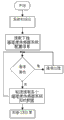
Fig. 2 is the using method schematic diagram of optical fiber Temperature and Humidity Sensor System in Fig. 1.
Fig. 3 is the using method schematic diagram of repeater in Fig. 1.
Fig. 4 is the using method schematic diagram of router in Fig. 1.
Fig. 5 is the using method schematic diagram of terminal receiver in Fig. 1.
In figure: aerial temperature and humidity sensor 61 in monitoring system 6, storehouse, gas detector 62, fibre optic temperature sensor 63, storehouse outer air Temperature Humidity Sensor 7, ventilation equipment 8, LED screen 9, warning system 10 in optical fiber Temperature and Humidity Sensor System 1, repeater 2, router three, terminal receiver 4, host computer 5, storehouse.
Embodiment
Below in conjunction with accompanying drawing explanation and embodiment, the utility model is described in further detail.
Referring to figure 1 – Fig. 5, a kind of grain depot intelligent comprehensive control system, comprise host computer 5 and a plurality of Temperature and Humidity Sensor System, and an end of described Temperature and Humidity Sensor System is connected with monitoring system in storehouse 6, and the other end is connected with host computer 5;
Described grain depot intelligent comprehensive control system also comprises repeater 2, router three and terminal receiver 4; In described storehouse, monitoring system 6 comprises aerial temperature and humidity sensor 61 in storehouse, gas detector 62 and a plurality of fibre optic temperature sensor 63; Described Temperature and Humidity Sensor System is optical fiber Temperature and Humidity Sensor System 1;
In described storehouse, the output terminal of aerial temperature and humidity sensor 61, gas detector 62, fibre optic temperature sensor 63 is connected with the input end of optical fiber Temperature and Humidity Sensor System 1, the output terminal of optical fiber Temperature and Humidity Sensor System 1, storehouse outer air Temperature Humidity Sensor 7 is connected with the input end of repeater 2, the output terminal of repeater 2 is connected with the input end of ventilation equipment 8, LED screen 9, router three, the output terminal of router three is connected with host computer 5 after terminal receiver 4, and is connected with warning system 10 on terminal receiver 4.
The quantity of described optical fiber Temperature and Humidity Sensor System 1 is 20 of 1 –, and the quantity of the corresponding fibre optic temperature sensor 63 of each optical fiber Temperature and Humidity Sensor System 1 is 256 of 1 –.
Described gas detector 62 comprises carbon dioxide detector, hydrogen phosphide detector, oxygen sensor and nitrogen detector.
Described optical fiber Temperature and Humidity Sensor System 1, repeater 2, router three, terminal receiver 4 all adopt the STM32 microprocessor; Described optical fiber Temperature and Humidity Sensor System 1 is arranged in silo, and repeater 2, LED screen 9, ventilation equipment 8 all are arranged on the silo exterior wall, and terminal receiver 4, host computer 5 are installed in duty room.
Described optical fiber Temperature and Humidity Sensor System 1 is connected with repeater 2 by 485 communication modules, repeater 2 is connected with router three by the Zigbee communication, router three is connected with terminal receiver 4 by the CAN bus, and terminal receiver 4 is connected with host computer 5 by the usb communication mode.
Described warning system 10 comprises acoustic-optic alarm, automatically sends short message apparatus, automatic poking phone with mobile telephone device and fixed line warning device automatically; Be connected with real-time display device, printing device and memory device on described host computer 5.
The quantity of described repeater 2 is a plurality of, and repeater 2 is corresponding one by one with silo.
A kind of using method of above-mentioned grain depot intelligent comprehensive control system, described using method comprises the following steps:
The using method of optical fiber Temperature and Humidity Sensor System 1: after bringing into operation, first carry out the system initialization operation, after system initialization finishes, scan again the configuration of probe on fibre optic temperature sensor 63, then carry out the probe data initialization operation, see again repeater 2 has or not and send communication request, if communication request is arranged, communicate processing, be that optical fiber Temperature and Humidity Sensor System 1 is by the probe measured temperature of its collection, indoor temperature and humidity, the data of four kinds of gas concentrations send repeater 2 to, if without communication request, to the probe measured temperature, indoor temperature and humidity, the collection that the data of four kinds of gas concentrations are circulated, analyze and calculate, and the arrival of wait repeater 2 communication request,
The using method of repeater 2: after bringing into operation, first carry out the initialization operation of system, read again the configuration information of each optical fiber Temperature and Humidity Sensor System 1 of lower extension, then see router three has or not and send communication request, if communication request is arranged, communicate task, be that repeater 2 carries out data communication through router three and terminal receiver 4, if without communication request, to each optical fiber Temperature and Humidity Sensor System 1 articulated under it, send in turn the probe measured temperature that communications command monitors to collect each optical fiber Temperature and Humidity Sensor System 1, indoor temperature and humidity, the data of four kinds of gas concentrations, after Data Collection is complete, again to data analysis to open or to close ventilation equipment 8, and the data of collecting are carried out to buffer memory and inquire about for higher level's router three, simultaneously, the data that read storehouse outer air Temperature Humidity Sensor 7 refresh in the lump on LED screen 9 and show with the data that itself and optical fiber Temperature and Humidity Sensor System 1 are sent,
The using method of router three: after bringing into operation, first carry out the initialization operation of system, send in turn communications command to collect the probe measured temperature of silo to each repeater 2 articulated under it again, indoor temperature and humidity, four kinds of gas concentrations, outside storehouse, the data of humiture are for the inquiry of terminal receiver 4, then see terminal receiver 4 has or not and send communication request, if communication request is arranged, communicate task, be that router three sends the data of each repeater 2 of its inquiry to terminal receiver 4, if without communication request, each repeater 2 that continues to articulate under it sends communications command in turn to collect the data of each silo,
The using method of terminal receiver 4: after bringing into operation, first carry out the initialization operation of system, read again the configuration information of each repeater 2 by router three, then see external unit or PC end program have or not to send communications command, if without communications command, wait for the arrival of communications command, if communications command is arranged, the silo real time data of sending to each repeater 2 of router three wheel continuous query, go forward side by side line number according to one's analysis, as abnormal as data, reported to the police to get rid of the grain feelings abnormal; If data are normal, see again external unit or PC end program have or not to send communications command, circulation is carried out successively.
The using method of described optical fiber Temperature and Humidity Sensor System 1: described system initialization operation comprises that system configuration information initialization, the initialization of system indication LED lamp, debugging initialization of output port, relay station 485 communication initialization, gas detecting instrument communication initialization, temperature sensor initialization, Temperature Humidity Sensor initialization, LEDPD switching initialization, ADC gather initialization, independent house dog initialization.
In the using method of described repeater 2: when repeater 2 reads the grain temperature abnormality that in silo, certain fibre optic temperature sensor 63 records, or the gas concentration that records of gas detector 62 also can show corresponding information on LED screen 9 while exceeding standard.
The utility model principle:
One, major equipment and function thereof:
Referring to Fig. 1, the utility model mainly is comprised of optical fiber Temperature and Humidity Sensor System, repeater, router, terminal receiver and PC (host computer) five parts, and its major function is as follows:
The optical fiber Temperature and Humidity Sensor System: major function is the data such as each gas concentration in aerial temperature and humidity data in the temperature data, silo of grain in the acquisition and processing silo, silo.
Repeater: major function is that router is controlled, sent data to the data, data analysis, the ventilation equipment that receive the transmission of optical fiber Temperature and Humidity Sensor System automatically.
Router: major function is that the data from repeater are sent to terminal receiver by wireless mode, because terminal receiver often is placed in Indoor environment with a varied topography, therefore, for ensureing signal intensity, takes CAN wire communication mode.
Terminal receiver: the bridge that connects optical fiber Temperature and Humidity Sensor System, repeater and host computer, provide sound and light alarm simultaneously while bearing the abnormal situation, automatically send note, automatic poking is phoned with mobile telephone and fixed line is reported to the police, while spending over 30 as the temperature of grain in silo, will report to the police.
Optical fiber Temperature and Humidity Sensor System, repeater, router, terminal receiver all adopt the STM32 microprocessor: the STM32 microprocessor is to use at present 32 the most general ARM, have cheap, stable performance, powerful, speed is fast, the advantages such as antijamming capability is strong are applicable to industrial environment very much.
Repeater is connected with router by the Zigbee communication, and: Zigbee can free networking, facilitate the network coverage, and relative cost is lower, technology maturation, and the multipoint wireless be well suited among a small circle covers, and low in energy consumption, and antijamming capability is strong.
Terminal receiver is connected with host computer by the usb communication mode: use be that USB virtual serial port mode is transmitted data, because RS232 serial ports has in the past almost disappeared from present PC mainboard, only having USB is the most general current interface, it is fast that USB has speed, expansion is convenient, supports the plurality of advantages such as hot-swappable.
Two, using method:
Referring to Fig. 1, using method mainly comprises the communication between optical fiber Temperature and Humidity Sensor System, repeater, router, terminal receiver four parts, 4 kinds of gas (nitrogen N in three temperature two wet (probe measured temperature, silo inner air and outer air humiture) and silo
2, oxygen O
2, carbon dioxide CO
2with hydrogen phosphide PH
3) measurement of concetration.The system assignment unique address fixing to optical fiber Temperature and Humidity Sensor System, repeater is in order to distinguish, when terminal receiver is received correct order, equipment to appointment (can be router, also can communication relays) send the communication request order, the equipment received orders will return to corresponding data to terminal receiver, and then turns back to external unit or the PC end watchdog routine of giving an order.
Referring to Fig. 2, the using method of optical fiber Temperature and Humidity Sensor System 1: after bringing into operation, first carry out the system initialization operation, comprise the system configuration information initialization, the initialization of system indication LED lamp, the debugging initialization of output port, relay station 485 communication initialization, gas detecting instrument communication initialization (with gas detector, communicating to detect gas parameter), the fibre optic temperature sensor initialization, the Temperature Humidity Sensor initialization, (each fibre optic temperature sensor is furnished with a probe to the LEDPD switching initialization, synchronization only has a probe to carry out work, therefore can switch in turn the LED lamp, make each probe Polling temperature parameter), ADC gathers initialization (the analog to digital conversion initialization of acquisition probe voltage), independent house dog initialization is (to a safeguard measure of system, the system that prevents is stuck), after system initialization finishes, (each probe can be for a position assignment information in silo to scan the configuration of popping one's head on fibre optic temperature sensor 63 again, here can the positional information of probe be configured), then (luminous intensity to each probe is carried out initialization to carry out the probe data initialization operation, have the primary calibration luminous intensity) thereafter, see again repeater 2 has or not and send communication request, if communication request is arranged, (repeater can communicate the optical fiber Temperature and Humidity Sensor System to communicate processing, read the data that the optical fiber Temperature and Humidity Sensor System gathers), be that optical fiber Temperature and Humidity Sensor System 1 is by the probe measured temperature of its collection, indoor temperature and humidity, the data of four kinds of gas concentrations send repeater 2 to, if without communication request, to the probe measured temperature, indoor temperature and humidity, the collection that the data of four kinds of gas concentrations are circulated, analyze and calculate (the temperature collected, humidity, gas concentration information is Data Analysis once, see if there is the information of exceeding standard, if the information of exceeding standard is arranged, can send out fault alarm information to repeater), and the arrival of wait repeater 2 communication request.
Referring to Fig. 3, the using method of repeater 2: after bringing into operation, first carry out the initialization operation of system, read again the configuration information (positional information of probe) of each optical fiber Temperature and Humidity Sensor System 1 of lower extension, then see router three has or not and send communication request, if communication request is arranged, communicate task (and the data communication between terminal receiver 4), be that repeater 2 carries out data communication through router three and terminal receiver 4, if without communication request, to each optical fiber Temperature and Humidity Sensor System 1 articulated under it, send in turn the probe measured temperature that communications command monitors to collect each optical fiber Temperature and Humidity Sensor System 1, indoor temperature and humidity, the data of four kinds of gas concentrations, after Data Collection is complete, again to data analysis to open or to close ventilation equipment 8, and the data of collecting are carried out to buffer memory and inquire about for higher level's router three, simultaneously, the data that read storehouse outer air Temperature Humidity Sensor 7 refresh in the lump on LED screen 9 and show with the data that itself and optical fiber Temperature and Humidity Sensor System 1 are sent.When repeater 2 reads the grain temperature abnormality that in silo, certain fibre optic temperature sensor 63 records, or the gas concentration that records of gas detector 62 also can show corresponding information on LED screen 9 while exceeding standard.
Referring to Fig. 4, the using method of router three: after bringing into operation, first carry out the initialization operation of system, send in turn communications command to collect the probe measured temperature of silo to each repeater 2 articulated under it again, indoor temperature and humidity, four kinds of gas concentrations, outside storehouse, the data of humiture are for the inquiry of terminal receiver 4, then see terminal receiver 4 has or not and send communication request, if communication request is arranged, the task that communicates is (as host computer need to be checked the temperature information that probe is surveyed, can send and read the real time data order terminal receiver 4, router three can be replied so, the data that will read from repeater 2 are issued terminal receiver 4, then be transmitted to the host computer on PC by terminal receiver), be that router three sends the data of each repeater 2 of its inquiry to terminal receiver 4, if without communication request, each repeater 2 that continues to articulate under it sends communications command in turn to collect the data of each silo.
Referring to Fig. 5, the using method of terminal receiver 4: after bringing into operation, first carry out the initialization operation of system, then read the configuration information of each repeater 2 by router three, then see external unit or PC end program have or not and send communications command, if without communications command, wait for the arrival of communications command, if communications command is arranged, the silo real time data of sending to each repeater 2 of router three wheel continuous query, go forward side by side line number according to one's analysis, as abnormal as data, reported to the police to get rid of the grain feelings abnormal; If data are normal, see again external unit or PC end program have or not to send communications command, circulation is carried out successively.
Therefore, the utility model has designed a kind of grain depot intelligent comprehensive control system, this design adopts optical fiber to carry out temperature survey and signal transmission, thoroughly eliminated the defect of electrical type temperature detection element, do not fear the phosphine gas corrosion, the combining wireless communication technology again, reduced the loaded down with trivial details and later maintenance cost of wired layout, make whole system more flexible and changeable, be easy to safeguard, can realize monitoring the dozens of silo simultaneously, the real-time monitoring of more than 300 temperature spot in each silo, and monitor the inside and outside air humidity of silo and temperature, 4 kinds of gas (nitrogen N simultaneously
2, oxygen O
2, carbon dioxide CO
2with hydrogen phosphide PH
3), have that cost is low, function is many and the high characteristics of reliability.Totally have the following advantages:
1. in silo, temperature sensing and signal transmission all adopt optical fiber, have stopped the various defects that electronic devices and components bring, and do not fear the hydrogen phosphide corrosion fully, low energy consumption, the low pollution, be not subject to electromagnetic interference (EMI), and essence is very safe, sampling number is adjustable, thermometric is accurate, highly sensitive, and antijamming capability is strong, there is no aging or malfunctioning phenomenon, 2. fibre optic temperature sensor is simple in structure, volume is little to save cost, installation, production, easy to maintenance, and maintenance cost is low; 3. Optical Fiber Transmission distance, the response time is short, highly sensitive, reusable, does not fear pollution, acid and alkali-resistance; 4. system signal transmission adopts radio communication, make system flexible and changeable, be easy to safeguard; Especially adopt 485 or CAN digital signal output, the expansion that facilitates system and external unit be connected; Host computer is equipped with the Internet/3G remote access function, at any time the situation of grain in each silo of remote inquiry; 5. positioning performance is good, the staff can react rapidly according to the address of each fibre optic temperature sensor, fibre optic temperature sensor quantity can be adjusted at random, can allow 20000 fibre optic temperature sensors to work alone to survey the temperature of diverse location point simultaneously, can monitor more or less a hundred silo simultaneously; 6. sound and light alarm is phoned with mobile telephone with SMS alarm, automatic poking and fixed line is reported to the police and to be combined, and realizes unmanned, reduces costs; 7. 4 kinds of gas detectors are installed in silo, and on the LED screen at chamber place each gas concentration of roll display, humiture, remind the interior working environment of staff's silo, support personnel's safety; 8. the inside and outside air themperature of silo, humidity are monitored simultaneously; 9. automatically control ventilation equipment, the intelligent Temperature-humidity of regulating; 10. Intelligent Recognition fibercuts position but (the optical fiber cable breaking part can return by antireflection part light, from emission punishment, leaves, and can calculate distance with optical time domain reflectometer, thereby judge breaking part).
Embodiment 1:
Referring to figure 1 – Fig. 5, a kind of grain depot intelligent comprehensive control system, this system is monitored a plurality of silos simultaneously, and each silo correspondence is provided with a repeater 2, and the silo of take is example, and its structure is as follows:
Aerial temperature and humidity sensor 61 in storehouse, gas detector 62(comprises carbon dioxide detector, the hydrogen phosphide detector, oxygen sensor and nitrogen detector), the included quantity of each optical fiber Temperature and Humidity Sensor System 1 of fibre optic temperature sensor 63(is 256 of 1 –) output terminal with optical fiber Temperature and Humidity Sensor System 1(quantity, be 20 of 1 –) input end be connected, optical fiber Temperature and Humidity Sensor System 1, the output terminal of storehouse outer air Temperature Humidity Sensor 7 is connected with the input end of repeater 2, the output terminal of repeater 2 and ventilation equipment 8, LED screen 9, the input end of router three is connected, the output terminal of router three is connected with host computer 5 after terminal receiver 4, and be connected with warning system 10(and comprise acoustic-optic alarm on terminal receiver 4, automatically send short message apparatus, automatic poking phone with mobile telephone device and automatic fixed line warning device) and display device in real time, printing device and memory device,
Described optical fiber Temperature and Humidity Sensor System 1, repeater 2, router three, terminal receiver 4 all adopt the STM32 microprocessor; Described optical fiber Temperature and Humidity Sensor System 1 is arranged in silo, and repeater 2, LED screen 9, ventilation equipment 8 all are arranged on the silo exterior wall, and terminal receiver 4, host computer 5 are installed in duty room; Described optical fiber Temperature and Humidity Sensor System 1 is connected with repeater 2 by 485 communication modules, repeater 2 is connected with router three by the Zigbee communication, router three is connected with terminal receiver 4 by the CAN bus, and terminal receiver 4 is connected with host computer 5 by the usb communication mode.
A kind of using method of above-mentioned grain depot intelligent comprehensive control system, described using method comprises the following steps:
The using method of optical fiber Temperature and Humidity Sensor System 1: after bringing into operation, first carry out the system initialization operation, comprise the system configuration information initialization, the initialization of system indication LED lamp, the debugging initialization of output port, relay station 485 communication initialization, the gas detecting instrument communication initialization, the temperature sensor initialization, the Temperature Humidity Sensor initialization, the LEDPD switching initialization, ADC gathers initialization, independent house dog initialization, after system initialization finishes, scan again the configuration of probe on fibre optic temperature sensor 63, then carry out the probe data initialization operation, see again repeater 2 has or not and send communication request, if communication request is arranged, communicate processing, optical fiber Temperature and Humidity Sensor System 1 is by the probe measured temperature of its collection, indoor temperature and humidity, the data of four kinds of gas concentrations send repeater 2 to, if without communication request, to the probe measured temperature, indoor temperature and humidity, the collection that the data of four kinds of gas concentrations are circulated, analyze and calculate, and wait for the arrival of repeater 2 communication request,
The using method of repeater 2: after bringing into operation, first carry out the initialization operation of system, read again the configuration information of each optical fiber Temperature and Humidity Sensor System 1 of lower extension, then see router three has or not and send communication request, if communication request is arranged, communicate task, be that repeater 2 carries out data communication through router three and terminal receiver 4, if without communication request, to each optical fiber Temperature and Humidity Sensor System 1 articulated under it, send in turn the probe measured temperature that communications command monitors to collect each optical fiber Temperature and Humidity Sensor System 1, indoor temperature and humidity, the data of four kinds of gas concentrations, after Data Collection is complete, again to data analysis to open or to close ventilation equipment 8, and the data of collecting are carried out to buffer memory and inquire about for higher level's router three, simultaneously, the data that read storehouse outer air Temperature Humidity Sensor 7 refresh in the lump on LED screen 9 and show with the data that itself and optical fiber Temperature and Humidity Sensor System 1 are sent, when repeater 2 reads the grain temperature abnormality that in silo, certain fibre optic temperature sensor 63 records, or the gas concentration that records of gas detector 62 also can show corresponding information on LED screen 9 while exceeding standard.
The using method of router three: after bringing into operation, first carry out the initialization operation of system, send in turn communications command to collect the probe measured temperature of silo to each repeater 2 articulated under it again, indoor temperature and humidity, four kinds of gas concentrations, outside storehouse, the data of humiture are for the inquiry of terminal receiver 4, then see terminal receiver 4 has or not and send communication request, if communication request is arranged, communicate task, be that router three sends the data of each repeater 2 of its inquiry to terminal receiver 4, if without communication request, each repeater 2 that continues to articulate under it sends communications command in turn to collect the data of each silo,
The using method of terminal receiver 4: after bringing into operation, first carry out the initialization operation of system, read again the configuration information of each repeater 2 by router three, then see external unit or PC end program have or not to send communications command, if without communications command, wait for the arrival of communications command, if communications command is arranged, the silo real time data of sending to each repeater 2 of router three wheel continuous query, go forward side by side line number according to one's analysis, as abnormal as data, reported to the police to get rid of the grain feelings abnormal; If data are normal, see again external unit or PC end program have or not to send communications command, circulation is carried out successively.
Claims (7)
1. a grain depot intelligent comprehensive control system, comprise host computer (5) and a plurality of Temperature and Humidity Sensor System, and an end of described Temperature and Humidity Sensor System is connected with monitoring system in storehouse (6), and the other end is connected with host computer (5), it is characterized in that:
Described grain depot intelligent comprehensive control system also comprises repeater (2), router (3) and terminal receiver (4); Monitoring system in described storehouse (6) comprises aerial temperature and humidity sensor (61) in storehouse, gas detector (62) and a plurality of fibre optic temperature sensor (63); Described Temperature and Humidity Sensor System is optical fiber Temperature and Humidity Sensor System (1);
Aerial temperature and humidity sensor (61) in described storehouse, gas detector (62), the output terminal of fibre optic temperature sensor (63) is connected with the input end of optical fiber Temperature and Humidity Sensor System (1), optical fiber Temperature and Humidity Sensor System (1), the output terminal of storehouse outer air Temperature Humidity Sensor (7) is connected with the input end of repeater (2), the output terminal of repeater (2) and ventilation equipment (8), LED shields (9), the input end of router (3) is connected, the output terminal of router (3) is connected with host computer (5) after terminal receiver (4), and be connected with warning system (10) on terminal receiver (4).
2. a kind of grain depot intelligent comprehensive control system according to claim 1, it is characterized in that: the quantity of described optical fiber Temperature and Humidity Sensor System (1) is 20 of 1 –, and the quantity of each corresponding fibre optic temperature sensor of optical fiber Temperature and Humidity Sensor System (1) (63) is 256 of 1 –.
3. a kind of grain depot intelligent comprehensive control system according to claim 1 and 2, it is characterized in that: described gas detector (62) comprises carbon dioxide detector, hydrogen phosphide detector, oxygen sensor and nitrogen detector.
4. a kind of grain depot intelligent comprehensive control system according to claim 1 and 2, it is characterized in that: described optical fiber Temperature and Humidity Sensor System (1), repeater (2), router (3), terminal receiver (4) all adopt the STM32 microprocessor; Described optical fiber Temperature and Humidity Sensor System (1) is arranged in silo, and repeater (2), LED screen (9), ventilation equipment (8) all are arranged on the silo exterior wall, and terminal receiver (4), host computer (5) are installed in duty room.
5. a kind of grain depot intelligent comprehensive control system according to claim 1 and 2, it is characterized in that: described optical fiber Temperature and Humidity Sensor System (1) is connected with repeater (2) by 485 communication modules, repeater (2) is connected with router (3) by the Zigbee communication, router (3) is connected with terminal receiver (4) by the CAN bus, and terminal receiver (4) is connected with host computer (5) by the usb communication mode.
6. a kind of grain depot intelligent comprehensive control system according to claim 1 and 2 is characterized in that: described warning system (10) comprises acoustic-optic alarm, automatically sends short message apparatus, automatic poking phone with mobile telephone device and fixed line warning device automatically; Described host computer is connected with real-time display device, printing device and memory device on (5).
7. a kind of grain depot intelligent comprehensive control system according to claim 1 and 2, it is characterized in that: the quantity of described repeater (2) is a plurality of, and repeater (2) is corresponding one by one with silo.
Priority Applications (1)
| Application Number | Priority Date | Filing Date | Title |
|---|---|---|---|
| CN201320354861.0U CN203376656U (en) | 2013-06-20 | 2013-06-20 | Intelligent integrated control system for grain depot |
Applications Claiming Priority (1)
| Application Number | Priority Date | Filing Date | Title |
|---|---|---|---|
| CN201320354861.0U CN203376656U (en) | 2013-06-20 | 2013-06-20 | Intelligent integrated control system for grain depot |
Publications (1)
| Publication Number | Publication Date |
|---|---|
| CN203376656U true CN203376656U (en) | 2014-01-01 |
Family
ID=49839179
Family Applications (1)
| Application Number | Title | Priority Date | Filing Date |
|---|---|---|---|
| CN201320354861.0U Withdrawn - After Issue CN203376656U (en) | 2013-06-20 | 2013-06-20 | Intelligent integrated control system for grain depot |
Country Status (1)
| Country | Link |
|---|---|
| CN (1) | CN203376656U (en) |
Cited By (7)
| Publication number | Priority date | Publication date | Assignee | Title |
|---|---|---|---|---|
| CN103324221A (en) * | 2013-06-20 | 2013-09-25 | 武汉新烽光电科技有限公司 | Grain depot intellectualization integrated control system and application method thereof |
| CN103885484A (en) * | 2014-03-08 | 2014-06-25 | 苏州边枫电子科技有限公司 | Monitoring system based on PC wired control |
| CN105183057A (en) * | 2015-10-14 | 2015-12-23 | 刘丰 | Grain bin temperature and humidity control system based on Zigbee technology |
| CN105807822A (en) * | 2016-03-16 | 2016-07-27 | 河南工业大学 | Intelligent detection and monitoring system for grain condition of grain depot |
| CN106547239A (en) * | 2016-11-02 | 2017-03-29 | 天津福威科技发展有限公司 | A kind of intelligent monitor system for silo |
| CN108887905A (en) * | 2018-07-23 | 2018-11-27 | 湖州圣远物流有限公司 | A kind of storage rack of included ladder |
| CN110927349A (en) * | 2019-12-27 | 2020-03-27 | 中央储备粮三明直属库有限公司 | A Lora-based granary gas monitoring system and method |
-
2013
- 2013-06-20 CN CN201320354861.0U patent/CN203376656U/en not_active Withdrawn - After Issue
Cited By (9)
| Publication number | Priority date | Publication date | Assignee | Title |
|---|---|---|---|---|
| CN103324221A (en) * | 2013-06-20 | 2013-09-25 | 武汉新烽光电科技有限公司 | Grain depot intellectualization integrated control system and application method thereof |
| CN103324221B (en) * | 2013-06-20 | 2015-06-10 | 武汉新烽光电科技有限公司 | Grain depot intellectualization integrated control system and application method thereof |
| CN103885484A (en) * | 2014-03-08 | 2014-06-25 | 苏州边枫电子科技有限公司 | Monitoring system based on PC wired control |
| CN105183057A (en) * | 2015-10-14 | 2015-12-23 | 刘丰 | Grain bin temperature and humidity control system based on Zigbee technology |
| CN105807822A (en) * | 2016-03-16 | 2016-07-27 | 河南工业大学 | Intelligent detection and monitoring system for grain condition of grain depot |
| CN106547239A (en) * | 2016-11-02 | 2017-03-29 | 天津福威科技发展有限公司 | A kind of intelligent monitor system for silo |
| CN108887905A (en) * | 2018-07-23 | 2018-11-27 | 湖州圣远物流有限公司 | A kind of storage rack of included ladder |
| CN110927349A (en) * | 2019-12-27 | 2020-03-27 | 中央储备粮三明直属库有限公司 | A Lora-based granary gas monitoring system and method |
| CN110927349B (en) * | 2019-12-27 | 2022-04-01 | 中央储备粮三明直属库有限公司 | Granary gas monitoring method based on Lora |
Similar Documents
| Publication | Publication Date | Title |
|---|---|---|
| CN103324221B (en) | Grain depot intellectualization integrated control system and application method thereof | |
| CN102999071B (en) | Switch cabinet environment intelligent monitoring and processing system based on wireless network | |
| CN110739772A (en) | Intelligent power distribution operation and maintenance system | |
| CN201444252U (en) | Wireless warehouse monitoring system based on ZigBee | |
| CN201638379U (en) | Wireless temperature and humidity monitoring system for warehousing environment | |
| CN105547483A (en) | Method for real-time temperature measurement of switch cabinet of networking infrared matrix | |
| CN113643515A (en) | Combustible dust automatic identification judges and alarm system | |
| CN104849640A (en) | Fault diagnosis system for distribution network based on double threshold values | |
| CN110428573A (en) | Fire Safety Monitoring System for Cable Shafts of High-rise Direct Supply Community Based on Beidou Technology | |
| CN105971671A (en) | Power cable tunnel fire protection system based on wireless sensor network | |
| CN102750799B (en) | Direct current transmission line forest fire monitoring device based on space ion current density | |
| CN211651687U (en) | A real-time dynamic monitoring system based on the comprehensive environment of substation cable trench | |
| CN108961691A (en) | Industry and commercial use gas alarm Internet of things system | |
| CN205427566U (en) | Long -range basic station monitor system based on internet | |
| CN205037923U (en) | Environmental monitor and environmental monitoring system | |
| CN112665647A (en) | ZigBee-based power grid transformer remote online monitoring system | |
| CN205581259U (en) | GIS local discharge on -line monitoring system with little meteorological monitoring | |
| CN103680073A (en) | Wireless environment gas monitoring and alarming system | |
| CN210464555U (en) | Base station detection system | |
| Fengbo et al. | Design and development of forest fire monitoring terminal | |
| CN203249699U (en) | Power network operation equipment temperature sensing system based on technology of Internet of Things | |
| CN113033726A (en) | Underground cable inspection system and method | |
| CN203732962U (en) | Real-time wireless temperature monitoring system | |
| CN106251557A (en) | A kind of multiparameter temperature measuring type electrical fire monitoring system | |
| CN111024249A (en) | Cable branch box inspection temperature measurement terminal, system and method |
Legal Events
| Date | Code | Title | Description |
|---|---|---|---|
| C14 | Grant of patent or utility model | ||
| GR01 | Patent grant | ||
| AV01 | Patent right actively abandoned |
Granted publication date: 20140101 Effective date of abandoning: 20150610 |
|
| RGAV | Abandon patent right to avoid regrant |