CN203371446U - Socket spanner used for dismounting hydraulic cartridge valve - Google Patents
Socket spanner used for dismounting hydraulic cartridge valve Download PDFInfo
- Publication number
- CN203371446U CN203371446U CN201320408964.0U CN201320408964U CN203371446U CN 203371446 U CN203371446 U CN 203371446U CN 201320408964 U CN201320408964 U CN 201320408964U CN 203371446 U CN203371446 U CN 203371446U
- Authority
- CN
- China
- Prior art keywords
- cartridge valve
- hydraulic cartridge
- flat groove
- dismounting
- spanner
- Prior art date
- Legal status (The legal status is an assumption and is not a legal conclusion. Google has not performed a legal analysis and makes no representation as to the accuracy of the status listed.)
- Expired - Fee Related
Links
- 238000003754 machining Methods 0.000 abstract 1
- 238000000034 method Methods 0.000 description 4
- 230000009286 beneficial effect Effects 0.000 description 2
- 238000010586 diagram Methods 0.000 description 2
- 230000007812 deficiency Effects 0.000 description 1
- 238000005516 engineering process Methods 0.000 description 1
- 239000007788 liquid Substances 0.000 description 1
Images

Landscapes
- Valve Housings (AREA)
Abstract
The utility model relates to a spanner tool, in particular to a socket spanner used for dismounting a hydraulic cartridge valve. The socket spanner used for dismounting the hydraulic cartridge valve comprises a cylindrical spanner body with a cylindrical center through hole and is characterized in that a flat groove A and a flat groove B which are different in width are formed in the two ends of the spanner body respectively, and two groups of radial through holes close to the corresponding end portions of the spanner body respectively are formed in the barrel wall of the spanner body; the sinking depth of the flat groove A and the concave degree of the flat groove B are both larger than 11mm and smaller than 13mm, and the distance between each end point of the spanner body and the point of tangency of the bottom end of the far radial through hole is larger than 85mm and smaller than 100mm. Thus, the socket spanner used for dismounting the hydraulic cartridge valve has the advantages of thoroughly solving the problems existing in dismounting of the hydraulic cartridge valve, being low in cost, and not only facilitating self machining, but also being capable of protecting a valve rod well.
Description
(1) technical field
The utility model relates to a kind of manual tool of pulling, particularly a kind of box spanner for the dismounting hydraulic cartridge valve.
(2) background technology
Along with the fast development of hydraulic technique, at present the overall structure of hydraulic system requires more and more compactlyer, and that emerging hydraulic cartridge valve just progressively replaces is board-like, the tubular liquid pressure valve is widely used.Need according to hydraulic circuit design, usually need the installing hole on the valve piece by inserted valve to sink to valve piece 5~6mm, outer six side's total heights of inserted valve are the 11mm left and right, and the height that six sides protrude from valve piece outer surface so in addition only remains 5~6mm.At present, usually adopt common fork spanner to carry out the dismounting of hydraulic cartridge valve, but its shortcoming is that clamping thickness is too little, often causes outer six square end sections to be twisted bald situation; On the other hand, the centre position of outer six sides in valve rod on the plug-in mounting valve rod, being exposed at the outer shaft length of valve piece approximately has 80mm long, and existing box spanner length is inadequate, thereby can't use.
(3) summary of the invention
The utility model, in order to make up the deficiencies in the prior art, provides a kind of box spanner for the dismounting hydraulic cartridge valve of being convenient to process voluntarily, can also protect valve rod.
The utility model is achieved by the following technical solution:
A kind of box spanner for the dismounting hydraulic cartridge valve, comprise the cylindric wrench body with cylindric central through hole, it is characterized in that: described wrench body two ends offer respectively flat groove A and the flat groove B of different in width, offer two groups of radial direction through hole of close wrench body respective end respectively on the barrel of wrench body.
This practicality is for the box spanner of dismounting hydraulic cartridge valve, and it is characterized in that: the recessed degree of flat groove A and flat groove B all is greater than 11mm and is less than 13mm, and the wrench body end points is greater than 85mm with the distance at the point of contact, bottom of radial direction through hole at a distance and is less than 100mm.
Therefore, the beneficial effects of the utility model are: should thoroughly solve the dismounting to hydraulic cartridge valve for the box spanner of dismounting hydraulic cartridge valve, cost is very low, both has been convenient to process voluntarily, can protect valve rod again.
(4) accompanying drawing explanation
Below in conjunction with accompanying drawing, the utility model is further described.
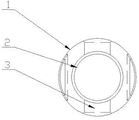
Accompanying drawing 1 is overall structure schematic diagram of the present utility model;
Accompanying drawing 3 is working state schematic representation of the present utility model.
In figure, 1 wrench body, 2 central through holes, 3 radial direction through hole, 4 hydraulic cartridge valve bars, 5 valve pieces, 6 flat groove A, 7 flat groove B.
(5) specific embodiment
Accompanying drawing is a kind of specific embodiment of the present utility model.This embodiment comprises the cylindric wrench body 1 with cylindric central through hole 2, it is characterized in that: described wrench body 1 two ends offer respectively flat groove A6 and the flat groove B7 of different in width, offer two groups of radial direction through hole 3 of close wrench body 1 respective end respectively on the barrel of wrench body 1; The recessed degree of flat groove A6 and flat groove B7 all is greater than 11mm and is less than 13mm, and wrench body 1 end points is greater than 85mm with the distance at the point of contact, bottom of radial direction through hole 3 at a distance and is less than 100m.
Adopt the box spanner for the dismounting hydraulic cartridge valve of the present utility model, as shown in Figure 3, hydraulic cartridge valve bar 4 is tightened on valve piece 5, and it is H that outer six side's parts of hydraulic cartridge valve bar 4 sink to the degree of depth in the counterbore of valve piece 5
1, outer six sides' thickness is H
2, the recessed degree of flat groove A6 and flat groove B7 is H
3, the external diameter of wrench body 1 is D
1, the internal diameter of central through hole 2 is D
2, the external diameter of hydraulic cartridge valve bar 4 is D
3, the counterbore external diameter is D
4, the flat size of outer six side that is stuck in hydraulic cartridge valve bar 4 is mostly B
1or B
2two kinds of specifications, hydraulic cartridge valve bar 4 self length is L
1, wrench body 1 end points and at a distance the distance between the central point of radial direction through hole 3 be L
2; During dismounting hydraulic cartridge valve bar 4, the flat groove A6 end of wrench body 1 or flat groove B7 end are inserted in counterbore, because of D
4>D
1, H
3>H
2, H
2be generally 11mm, D
2>D
3, flat groove A6 end or flat groove B7 end socket can contact fully with outer six sides of hydraulic cartridge valve bar 4 are flat, and hydraulic cartridge valve bar 4 overhanging ends can penetrate in the central through hole 2 of wrench body 1; Again because (L
2-d/2)>L
1, L
1be generally 85 ~ 86mm, only the thin rod of similar screwdriver and so on need be penetrated in the radial direction through hole 3 of flat groove B7 end or flat groove A6 end, can drive 4 rotations of hydraulic cartridge valve bar by turning wrench body 1, carry out the dismounting of hydraulic cartridge valve bar 4.
Therefore, the beneficial effects of the utility model are: should thoroughly solve the dismounting to hydraulic cartridge valve for the box spanner of dismounting hydraulic cartridge valve, cost is very low, both has been convenient to process voluntarily, can protect valve rod again.
Claims (2)
1. the box spanner for the dismounting hydraulic cartridge valve, comprise the cylindric wrench body (1) with cylindric central through hole (2), it is characterized in that: described wrench body (1) two ends offer respectively the flat groove A(6 of different in width) and flat groove B(7), offer two groups of radial direction through hole (3) of close wrench body (1) respective end respectively on the barrel of wrench body (1).
2. the box spanner for the dismounting hydraulic cartridge valve according to claim 1, it is characterized in that: flat groove A(6) and flat groove B(7) recessed degree all be greater than 11mm and be less than 13mm, wrench body (1) end points is greater than 85mm with the distance at the point of contact, bottom of radial direction through hole (3) at a distance and is less than 100mm.
Priority Applications (1)
| Application Number | Priority Date | Filing Date | Title |
|---|---|---|---|
| CN201320408964.0U CN203371446U (en) | 2013-07-10 | 2013-07-10 | Socket spanner used for dismounting hydraulic cartridge valve |
Applications Claiming Priority (1)
| Application Number | Priority Date | Filing Date | Title |
|---|---|---|---|
| CN201320408964.0U CN203371446U (en) | 2013-07-10 | 2013-07-10 | Socket spanner used for dismounting hydraulic cartridge valve |
Publications (1)
| Publication Number | Publication Date |
|---|---|
| CN203371446U true CN203371446U (en) | 2014-01-01 |
Family
ID=49833999
Family Applications (1)
| Application Number | Title | Priority Date | Filing Date |
|---|---|---|---|
| CN201320408964.0U Expired - Fee Related CN203371446U (en) | 2013-07-10 | 2013-07-10 | Socket spanner used for dismounting hydraulic cartridge valve |
Country Status (1)
| Country | Link |
|---|---|
| CN (1) | CN203371446U (en) |
Cited By (1)
| Publication number | Priority date | Publication date | Assignee | Title |
|---|---|---|---|---|
| CN119467485A (en) * | 2024-12-27 | 2025-02-18 | 北京天玛智控科技股份有限公司 | A test block structure, a test tool for a hydraulic valve, and a disassembly tool for a hydraulic valve |
-
2013
- 2013-07-10 CN CN201320408964.0U patent/CN203371446U/en not_active Expired - Fee Related
Cited By (1)
| Publication number | Priority date | Publication date | Assignee | Title |
|---|---|---|---|---|
| CN119467485A (en) * | 2024-12-27 | 2025-02-18 | 北京天玛智控科技股份有限公司 | A test block structure, a test tool for a hydraulic valve, and a disassembly tool for a hydraulic valve |
Similar Documents
| Publication | Publication Date | Title |
|---|---|---|
| CN202029096U (en) | Nipple assembling tool | |
| CN203579498U (en) | Multifunctional hexagon wrench | |
| CN203500227U (en) | T-bolt with antiskid teeth | |
| CN204308839U (en) | A kind of knife bar can bending antioverloading sleeve screw driver | |
| CN204076122U (en) | The T-shaped antioverloading screwdriver of a kind of bendable | |
| CN204308857U (en) | The T-shaped antioverloading screwdriver of a kind of folding type | |
| CN204308856U (en) | The adjustable T-shaped antioverloading screwdriver of a kind of folding type load | |
| CN207344470U (en) | A kind of multifunctional combination wrench | |
| CN203003768U (en) | Multifunctional screwdriver | |
| CN204308863U (en) | One can the T-shaped antioverloading screwdriver of bending | |
| CN201794886U (en) | Bolt easy to be fixed | |
| CN204209000U (en) | The curved mould adapter of a kind of bending machine | |
| CN204308862U (en) | The adjustable T-shaped antioverloading screwdriver of a kind of bendable load | |
| CN204149091U (en) | The T-shaped antioverloading screwdriver of a kind of bending dual-purpose type | |
| CN215617709U (en) | Wrench for sleeve type valve switch | |
| CN203665400U (en) | Tightening tool | |
| CN204308858U (en) | A kind of connecting rod can the adjustable T-shaped antioverloading screwdriver of bending load | |
| CN204308867U (en) | One can the adjustable T-shaped antioverloading screwdriver of bending load | |
| CN204308865U (en) | A kind of telescopic handle connecting rod can the adjustable antioverloading screwdriver of bending load | |
| CN202579568U (en) | Novel nut and mounting tool thereof | |
| CN204366836U (en) | A kind of knife bar can bending antioverloading screwdriver | |
| CN201841507U (en) | Screwdriver for nut assembly | |
| CN202318266U (en) | Multifunctional screwdriver head connecting rod | |
| CN204308861U (en) | The adjustable T-shaped antioverloading screwdriver of a kind of bending dual-purpose type load | |
| CN204308854U (en) | One can bending antioverloading screwdriver |
Legal Events
| Date | Code | Title | Description |
|---|---|---|---|
| C14 | Grant of patent or utility model | ||
| GR01 | Patent grant | ||
| CF01 | Termination of patent right due to non-payment of annual fee |
Granted publication date: 20140101 Termination date: 20140710 |
|
| EXPY | Termination of patent right or utility model |