CN203328252U - Cupboard with rotating bar counter - Google Patents
Cupboard with rotating bar counter Download PDFInfo
- Publication number
- CN203328252U CN203328252U CN2013203389281U CN201320338928U CN203328252U CN 203328252 U CN203328252 U CN 203328252U CN 2013203389281 U CN2013203389281 U CN 2013203389281U CN 201320338928 U CN201320338928 U CN 201320338928U CN 203328252 U CN203328252 U CN 203328252U
- Authority
- CN
- China
- Prior art keywords
- bar desk
- bar counter
- cupboard
- cabinet
- plate
- Prior art date
- Legal status (The legal status is an assumption and is not a legal conclusion. Google has not performed a legal analysis and makes no representation as to the accuracy of the status listed.)
- Expired - Lifetime
Links
- 238000010276 construction Methods 0.000 claims description 3
- 238000005406 washing Methods 0.000 description 3
- 238000010411 cooking Methods 0.000 description 2
- 238000005516 engineering process Methods 0.000 description 1
Images




Landscapes
- Tables And Desks Characterized By Structural Shape (AREA)
Abstract
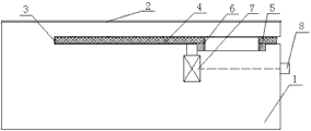
The utility model discloses a cupboard with a rotating bar counter. The cupboard with the rotating bar counter comprises a cupboard body and a counter top, wherein a bar counter clamping groove is formed in the upper portion of the cupboard body, a bar counter plate is arranged in the bar counter clamping groove, a driving motor which is connected with a rotating gear is arranged in the cupboard body, a control switch which is connected with the driving motor is arranged on a cupboard body face plate, and the bar counter plate is fixedly connected with the rotating gear. The bar counter plate is of a hidden type structure and fixed to the upper portion of the cupboard body so that the bar counter plate and the cupboard body can be of an integral structure, and therefore the cupboard is more attractive in overall structure. The cupboard is easy to operate when used, namely, the control switch is pressed down, the rotating gear is driven by a driving motor to rotate, the rotating gear drives the bar counter plate to rotate, and therefore the rotating folding function and the rotating unfolding function of the bar counter plate can be achieved. The rotating angle can be positioned when the control switch is manually controlled to be turned on and turned off.
Description
Technical field
The utility model relates to the kitchen cabinet field, specifically a kind of kitchen cabinet with the rotation bar desk.
Background technology
Cabinet, as the term suggests be exactly the cabinet be arranged in kitchen, its function comprises washing, arranges, cooks, stores four kinds.Cabinet generally comprises cabinet and is arranged at the table top on cabinet top, and cabinet is for storing article, and table top is for washing, cooking, culinary art.So, for aspect people washing, cooking, culinary art, the height of cabinet table surface operated by rotary motion is commonly 80-100CM.Along with the raising of people's living standard, people are for the pursuit of quality of the life, and people like the limit, bar desk that spare time sits at home to taste some good wine.General bar desk is arranged in the middle of the parlor in family, after people have cooked food, while wanting to taste some good wine, just food need to be moved on the bar desk in parlor, very trouble.
The utility model content
The technical problems to be solved in the utility model is to provide a kind of kitchen cabinet with the rotation bar desk, and it can be according to actual needs, Unscrew bar desk plate, or rotate and pack up, simple to operate, and structure is attractive in appearance.
The technical solution of the utility model is:
A kind of kitchen cabinet with the rotation bar desk, include cabinet and table top, it is characterized in that: the top of described cabinet is provided with the bar desk draw-in groove, be provided with the bar desk plate in the draw-in groove of bar desk, be provided with the drive motors be connected with swing pinion in cabinet, be provided with the gauge tap be connected with drive motors on the cabinet panel, described bar desk plate is fixedly connected with swing pinion.
The inner of described bar desk draw-in groove is enclosed construction, and outer end is open type.
Be provided with circular port on the plate of described bar desk, it is overlapped that described swing pinion is arranged at inner ring and the circular port of the below of bar desk plate and swing pinion, and an adapter sleeve is set in swing pinion inner ring and circular port, and is fixedly connected with respectively with both.
Described swing pinion is adjacent to the outer end of bar desk draw-in groove.
Advantage of the present utility model:
Bar desk of the present utility model plate is concealed structure, is fixed in cabinet top, presents the structure with kitchen cabinet cabinet integral type, makes the kitchen cabinet overall structure more attractive in appearance; It is simple to operate when the utility model is used, press gauge tap, the drive motors driven wheel rotates, the rotation of gear driven bar desk plate, realize the function that Unscrew and rotation are packed up, and the anglec of rotation can realize by the start and stop of manual control gauge tap the location of different angles.
The accompanying drawing explanation
Fig. 1 is the front view of the utility model bar desk plate collapsed state.
Fig. 2 is the cutaway view of the utility model bar desk plate collapsed state.
Fig. 3 is the front view of the utility model bar desk plate open mode.
Fig. 4 is the cutaway view of the utility model bar desk plate open mode.
Fig. 5 is the top view of the utility model bar desk plate open mode.
The specific embodiment
See Fig. 1, Fig. 2, Fig. 3, Fig. 4 and Fig. 5, a kind of kitchen cabinet with the rotation bar desk, include cabinet 1, table top 2, be arranged at the bar desk draw-in groove 3 on cabinet top, be arranged at the bar desk plate 4 in bar desk draw-in groove 3, be arranged at the overlapped swing pinion 5 of the circular port of the below of bar desk plate 4 and inner ring and bar desk plate 4, be set in the adapter sleeve 6 in swing pinion 5 inner rings and circular port, be arranged in cabinet 1 and the drive motors 7 be connected with swing pinion 5 be arranged at cabinet 1 panel on and the gauge tap 8 that is connected with drive motors 7; Wherein, the inner of bar desk draw-in groove 3 is that enclosed construction, outer end are open type, and adapter sleeve 6 is fixedly connected with bar desk plate 4, swing pinion 5 respectively, and swing pinion 5 is adjacent to the outer end of bar desk draw-in groove 3.
Claims (4)
- One kind with the rotation bar desk kitchen cabinet, include cabinet and table top, it is characterized in that: the top of described cabinet is provided with the bar desk draw-in groove, be provided with the bar desk plate in the draw-in groove of bar desk, be provided with the drive motors be connected with swing pinion in cabinet, be provided with the gauge tap be connected with drive motors on the cabinet panel, described bar desk plate is fixedly connected with swing pinion.
- According to claim 1 a kind of with the rotation bar desk kitchen cabinet, it is characterized in that: the inner of described bar desk draw-in groove is enclosed construction, outer end is open type.
- According to claim 1 a kind of with the rotation bar desk kitchen cabinet, it is characterized in that: on the plate of described bar desk, be provided with circular port, it is overlapped that described swing pinion is arranged at inner ring and the circular port of the below of bar desk plate and swing pinion, one adapter sleeve is set in swing pinion inner ring and circular port, and is fixedly connected with respectively with both.
- According to claim 2 a kind of with the rotation bar desk kitchen cabinet, it is characterized in that: described swing pinion is adjacent to the outer end of bar desk draw-in groove.
Priority Applications (1)
| Application Number | Priority Date | Filing Date | Title |
|---|---|---|---|
| CN2013203389281U CN203328252U (en) | 2013-06-14 | 2013-06-14 | Cupboard with rotating bar counter |
Applications Claiming Priority (1)
| Application Number | Priority Date | Filing Date | Title |
|---|---|---|---|
| CN2013203389281U CN203328252U (en) | 2013-06-14 | 2013-06-14 | Cupboard with rotating bar counter |
Publications (1)
| Publication Number | Publication Date |
|---|---|
| CN203328252U true CN203328252U (en) | 2013-12-11 |
Family
ID=49696968
Family Applications (1)
| Application Number | Title | Priority Date | Filing Date |
|---|---|---|---|
| CN2013203389281U Expired - Lifetime CN203328252U (en) | 2013-06-14 | 2013-06-14 | Cupboard with rotating bar counter |
Country Status (1)
| Country | Link |
|---|---|
| CN (1) | CN203328252U (en) |
Cited By (1)
| Publication number | Priority date | Publication date | Assignee | Title |
|---|---|---|---|---|
| CN103284490A (en) * | 2013-06-14 | 2013-09-11 | 志邦厨柜股份有限公司 | Kitchen cabinet with rotating bar counter |
-
2013
- 2013-06-14 CN CN2013203389281U patent/CN203328252U/en not_active Expired - Lifetime
Cited By (1)
| Publication number | Priority date | Publication date | Assignee | Title |
|---|---|---|---|---|
| CN103284490A (en) * | 2013-06-14 | 2013-09-11 | 志邦厨柜股份有限公司 | Kitchen cabinet with rotating bar counter |
Similar Documents
| Publication | Publication Date | Title |
|---|---|---|
| CN202868783U (en) | Linked pull-out support plate device for microwave oven | |
| CN204032663U (en) | Multifunctional cold and warm deformation dining table | |
| CN103653788B (en) | Fully-automatic hotpot table | |
| CN203328253U (en) | Wine storing rack installed on kitchen cabinet | |
| CN201827944U (en) | Automatic turn-over type oil fume extractor | |
| CN103284490A (en) | Kitchen cabinet with rotating bar counter | |
| CN203676460U (en) | Full-automatic hot pot table | |
| CN211092480U (en) | Fold shadow tea table | |
| CN201827943U (en) | Range hood with drop leaf | |
| CN203873307U (en) | Kitchen cabinet convenient to use | |
| CN203378986U (en) | Rice cooker | |
| CN205514190U (en) | A rotatory glass door structure of detachable for toasting equipment | |
| CN107581781A (en) | A kind of smart home automatic lifting dining table | |
| CN204015589U (en) | A kind of locking wine cabinet that can freely assemble | |
| CN2694819Y (en) | Automatic rotating dining table | |
| AU2019101115A4 (en) | A Liftable Double Pot | |
| CN204146635U (en) | Liftable bookcase revolving | |
| CN202060567U (en) | Multiple-dish heat insulation wine-warming lotus-shaped combined hot pot | |
| CN202567102U (en) | Cabinet with bar counter | |
| CN202619338U (en) | Automatic cooker | |
| CN203302629U (en) | Novel electric dinner table | |
| CN208909515U (en) | A kind of rotary low temperature cake showing cabinet | |
| CN202588812U (en) | Multifunctional electric table | |
| CN203137516U (en) | Automatic type dining table | |
| CN204260142U (en) | A kind of easy-to-use round table |
Legal Events
| Date | Code | Title | Description |
|---|---|---|---|
| C14 | Grant of patent or utility model | ||
| GR01 | Patent grant | ||
| CX01 | Expiry of patent term | ||
| CX01 | Expiry of patent term |
Granted publication date: 20131211 |