CN203305250U - Laminaria japonica filament cutter - Google Patents
Laminaria japonica filament cutter Download PDFInfo
- Publication number
- CN203305250U CN203305250U CN201320297618XU CN201320297618U CN203305250U CN 203305250 U CN203305250 U CN 203305250U CN 201320297618X U CN201320297618X U CN 201320297618XU CN 201320297618 U CN201320297618 U CN 201320297618U CN 203305250 U CN203305250 U CN 203305250U
- Authority
- CN
- China
- Prior art keywords
- cutter
- cutter shaft
- feeding table
- laminaria japonica
- roll body
- Prior art date
- Legal status (The legal status is an assumption and is not a legal conclusion. Google has not performed a legal analysis and makes no representation as to the accuracy of the status listed.)
- Expired - Fee Related
Links
- 241000015177 Saccharina japonica Species 0.000 title abstract description 11
- 238000003780 insertion Methods 0.000 claims description 4
- 230000037431 insertion Effects 0.000 claims description 4
- 239000002994 raw material Substances 0.000 abstract description 6
- 238000004519 manufacturing process Methods 0.000 abstract description 3
- 238000005520 cutting process Methods 0.000 abstract 1
- 238000000034 method Methods 0.000 description 2
- 241000512259 Ascophyllum nodosum Species 0.000 description 1
- 230000015572 biosynthetic process Effects 0.000 description 1
- 238000010586 diagram Methods 0.000 description 1
- 230000000694 effects Effects 0.000 description 1
- 230000008676 import Effects 0.000 description 1
- 238000009434 installation Methods 0.000 description 1
- 238000005096 rolling process Methods 0.000 description 1
- 150000003839 salts Chemical class 0.000 description 1
- 239000013535 sea water Substances 0.000 description 1
Images


Landscapes
- Formation And Processing Of Food Products (AREA)
Abstract
The utility model belongs to the technical field of food processing machines to resolve the problems that an existing laminaria japonica filament cutter is low in efficiency and low in safety factor when carrying out filament cutting operation on fresh laminaria japonica raw materials. A laminaria japonica filament cutter comprises a machine frame, wherein a feeding table surface is installed at the top of the machine frame, a first cutter shaft and a second cutter shaft which rotate in the opposite directions are installed at the front end of the feeding table surface and are driven by a motor at the bottom of the machine frame, round cutter blades are installed on the first cutter shaft and the second cutter shaft at intervals, and the cutter blades on the two cutter shafts are inserted into one another in a staggered mode. The laminaria japonica filament cutter is characterized in that the feeding table surface is formed by combing a plurality of roller bodies capable of rotating freely. The laminaria japonica filament cutter is reasonable in structure, easy and convenient to operate and capable of being widely applied to production and processing of laminaria japonica.
Description
Technical field
The utility model belongs to the food processing machinery technical field, is specifically related to a kind of laminarian slitter.
Background technology
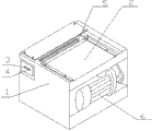
The effect of laminarian slitter is that sea-tangle is cut into to uniform Shredded kelp with eating of being convenient for people to.The laminarian slitter used at present as shown in Figure 1, it comprises frame 1, feeding table top 2 is installed at frame 1 top, front end at feeding table top 2 is installed the first cutter shaft 3 and the second cutter shaft 4 that subtend is rotated, the first cutter shaft and the second cutter shaft are driven by the motor 6 of frame bottom, at interval on the first cutter shaft and the second cutter shaft, the interlaced insertion of blade 5 on 5, two cutter shafts of circular shear blade is installed.As seen from Figure 1, when sea-tangle is laid on the feeding table top, manually promote sea-tangle, when the end of sea-tangle with after blade on the first cutter shaft and the second cutter shaft contacts on by two cutter shafts staggered blade bite, under the rotation of cutter shaft, sea-tangle is drawn between two cutter shafts and completes the chopping action.Because the raw material of the sea-tangle for chopping used at present has two kinds, Fresh Laminaria Japonica and pickled sea-tangle, in the process of using filament cutter, find, when using pickled sea-tangle raw material, due to sea-tangle raw material relatively dry, and on the sea-tangle body, being stained with the salt grain, sea-tangle is adopted artificial the promotion relatively easily on the feeding table top.And when using Fresh Laminaria Japonica, owing on the sea-tangle body, being stained with a large amount of seawater, sea-tangle also is with toughness simultaneously, now sea-tangle is laid on the feeding table top, forms vacuum state between sea-tangle and feeding table top, and sea-tangle is fitted on the feeding table top tightly, now adopt artificial the promotion, sea-tangle is difficult to be moved, and the processing staff must start the sea-tangle end with hand it is sent between the filament cutter cutter shaft, and the mode that is driven, manually held sea-tangle by cutter shaft completes the chopping operation.Like this one is seriously to have reduced production efficiency, the 2nd, to operating personnel, bring potential safety hazard.
Summary of the invention
The low technical problem of inefficiency, safety coefficient existed in use Fresh Laminaria Japonica raw material carries out the chopping operating process for solving current laminarian slitter, it is a kind of rational in infrastructure, easy and simple to handle that the utility model provides, the laminarian slitter that can effectively enhance productivity.
For realizing above-mentioned technical purpose, the technical solution adopted in the utility model is: laminarian slitter, comprise frame, frame top is installed the feeding table top, front end at the feeding table top is installed the first cutter shaft and the second cutter shaft that subtend is rotated, the first cutter shaft and the second cutter shaft are by the driven by motor of frame bottom, circular shear blade is installed at interval on the first cutter shaft and the second cutter shaft, the interlaced insertion of blade on two cutter shafts, it is characterized in that: described feeding table top is combined by the some roll bodies that freely rotate.
Described feeding table top also comprises that two be used to supporting the stand of roll body, and stand is arranged on the both sides of frame, and roll body is installed between stand.
Described stand is 90 ° of corner brackets, and it comprises surface plate and vertical panel, and surface plate and frame are fixed, and vertical panel is provided be used to the axis hole of roll body is installed.
The vertical panel of described its front end of stand stretches out surface plate and is provided with inclined-plane.
The both ends of described roll body are provided with respectively bearing.
Above-mentioned roll body is plastic tube.
As can be known by foregoing description, the feeding table top of this laminarian slitter is by the flat board roll body assembled state of rolling instead, and sea-tangle is mobile on the feeding table top to roll mobilely by mobile the changing over of sliding, and its frictional resistance obviously reduces.During work, the sea-tangle raw material be laid on the feeding table top, touch with have gentle hands moving, sea-tangle can freely move ahead, owing between roll body and roll body, having space, moisture on Fresh Laminaria Japonica is by under all right drop in this space, between sea-tangle and feeding table top, can't form the vacuum bond state, it is convenient and swift that feeding becomes.Use this laminarian slitter obviously to enhance productivity, during feeding, staff does not form and contacts with rotor, can guarantee operating personnel's personal safety.This laminarian slitter is rational in infrastructure, easy and simple to handle, can be widely used in the production and processing of sea-tangle.
The accompanying drawing explanation
Fig. 1 is the structural representation of the laminarian slitter of prior art.
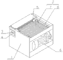
Fig. 2 is the structural representation of laminarian slitter of the present utility model.
Fig. 3 is the structural representation of the feeding table top of the utility model laminarian slitter.
Fig. 4 is the structural representation of stand.
Fig. 5 is the utility model roll body end face structure schematic diagram.
In figure, 1, frame, 2, the feeding table top, the 3, first cutter shaft, the 4, second cutter shaft, 5, blade, 6, motor, 7, roll body, 8, stand, 9, surface plate, 10, vertical panel, 11, axis hole, 12, bearing, 13, dead eye.
The specific embodiment
Below in conjunction with drawings and Examples, the utility model is described further.
As shown in Figure 2, laminarian slitter, comprise frame 1, frame top is installed feeding table top 2, front end at feeding table top 2 is installed the first cutter shaft 3 and the second cutter shaft 4 that subtend is rotated, the first cutter shaft 3 and the second cutter shaft 4 are driven by the motor 6 of frame bottom, at interval on the first cutter shaft and the second cutter shaft, the interlaced insertion of blade 5 on 5, two cutter shafts of circular shear blade are installed.
As shown in Figure 2, the feeding table top 2 of this laminarian slitter is combined by the some roll bodies that freely rotate 7 on the stand 8 that is arranged on frame 1 both sides.
The concrete structure of the feeding table top 2 of this filament cutter as shown in Figure 3, Figure 4.
As shown in Figure 3, this feeding table face comprises two stands 8 be used to supporting roll body, and with reference to shown in Figure 2, two stands 8 are arranged on respectively the both sides of frame 1, and roll body 7 is installed between stand.
As shown in Figure 4, this stand 8 is 90 ° of corner brackets, and it comprises surface plate 9 and vertical panel 10, and vertical panel 10 is provided with the axis hole 11 be used to roll body is installed.
During installation, install by the axis hole 11 on the vertical panel 10 of rotating shaft and stand 8 end of roll body 7, and roll body 7 is free to rotate between two stands.
As a kind of preferred mounting means, as shown in Figure 5, roll body adopts plastic tube in the setting of roll body 7 ends, and bearing 12 is installed in the inner chamber of roll body 7 ends, coordinates with the axis hole 11 on vertical panel 10 by dead eye 13, adopts rotating shaft to connect.Certainly except aforesaid way, for reducing costs, can end cap be set in roll body 7 ends, on end cap, leave shaft hole, shaft hole directly adopts rotating shaft to be connected with the axis hole on vertical panel.This kind connected mode roll body also can be realized rotating, but the connected mode that flexibility provides not as this optimal way, but cost can be significantly reduced.
As shown in Figure 2, after the stand 8 on feeding table top 2 completes combination with roll body 7, utilize the surface plate 9 of stand 8 to fix with the frame both sides.For preventing that staff from forming and contacting with rotor, as shown in Figure 2, feeding table top 2 integral body are higher than two rotors, and ,Gai inclined-plane, the downward-sloping formation of the front end of feeding table top inclined-plane imports the sea-tangle front end between two rotors.During concrete the making, as shown in Figure 4, the front end of the vertical panel 10 of stand 8 stretches out surface plate 9 front ends, and be provided with inclined-plane at this end, axis hole position on the vertical panel external part lower than the axis hole position of other positions on vertical panel, after roll body has been installed, can form the feeding face that front end tilts relatively like this.
Claims (6)
1. laminarian slitter, comprise frame, frame top is installed the feeding table top, front end at the feeding table top is installed the first cutter shaft and the second cutter shaft that subtend is rotated, the first cutter shaft and the second cutter shaft are by the driven by motor of frame bottom, circular shear blade is installed at interval on the first cutter shaft and the second cutter shaft, the interlaced insertion of blade on two cutter shafts, and it is characterized in that: described feeding table top is combined by the some roll bodies that freely rotate.
2. laminarian slitter according to claim 1, it is characterized in that: described feeding table top also comprises that two be used to supporting the stand of roll body, and stand is arranged on the both sides of frame, and roll body is installed between stand.
3. laminarian slitter according to claim 2, it is characterized in that: described stand is 90 ° of corner brackets, and it comprises surface plate and vertical panel, and surface plate and frame are fixed, vertical panel is provided be used to the axis hole of roll body is installed.
4. laminarian slitter according to claim 3, it is characterized in that: the vertical panel of described its front end of stand stretches out surface plate and is provided with inclined-plane.
5. laminarian slitter according to claim 1, it is characterized in that: the both ends of described roll body are provided with respectively bearing.
6. laminarian slitter according to claim 1, it is characterized in that: described roll body is plastic tube.
Priority Applications (1)
| Application Number | Priority Date | Filing Date | Title |
|---|---|---|---|
| CN201320297618XU CN203305250U (en) | 2013-05-28 | 2013-05-28 | Laminaria japonica filament cutter |
Applications Claiming Priority (1)
| Application Number | Priority Date | Filing Date | Title |
|---|---|---|---|
| CN201320297618XU CN203305250U (en) | 2013-05-28 | 2013-05-28 | Laminaria japonica filament cutter |
Publications (1)
| Publication Number | Publication Date |
|---|---|
| CN203305250U true CN203305250U (en) | 2013-11-27 |
Family
ID=49611484
Family Applications (1)
| Application Number | Title | Priority Date | Filing Date |
|---|---|---|---|
| CN201320297618XU Expired - Fee Related CN203305250U (en) | 2013-05-28 | 2013-05-28 | Laminaria japonica filament cutter |
Country Status (1)
| Country | Link |
|---|---|
| CN (1) | CN203305250U (en) |
Cited By (2)
| Publication number | Priority date | Publication date | Assignee | Title |
|---|---|---|---|---|
| CN104489896A (en) * | 2015-01-08 | 2015-04-08 | 云南中烟工业有限责任公司 | Reconstituted tobacco shredding device through ultrasonic waves |
| CN111347468A (en) * | 2020-03-26 | 2020-06-30 | 欧细邱 | Kelp is shred device in batches |
-
2013
- 2013-05-28 CN CN201320297618XU patent/CN203305250U/en not_active Expired - Fee Related
Cited By (4)
| Publication number | Priority date | Publication date | Assignee | Title |
|---|---|---|---|---|
| CN104489896A (en) * | 2015-01-08 | 2015-04-08 | 云南中烟工业有限责任公司 | Reconstituted tobacco shredding device through ultrasonic waves |
| CN104489896B (en) * | 2015-01-08 | 2017-01-04 | 云南中烟工业有限责任公司 | One utilizes ultrasound wave to carry out reconstituted tobacco shredding equipment |
| CN111347468A (en) * | 2020-03-26 | 2020-06-30 | 欧细邱 | Kelp is shred device in batches |
| CN111347468B (en) * | 2020-03-26 | 2021-05-04 | 赣州统茂塑胶五金有限公司 | Kelp is shred device in batches |
Similar Documents
| Publication | Publication Date | Title |
|---|---|---|
| CN205005807U (en) | Noodle press | |
| CN208512761U (en) | A kind of device of pounding medicine in a mortar for prepared slices of Chinese crude drugs Raw material processing | |
| CN202934621U (en) | Corn root cutting device | |
| CN202742406U (en) | Eccentric wheel cutter device of cowpea shredding machine | |
| CN205394765U (en) | Rotary cutting shaving machine | |
| CN103815538B (en) | A kind of knife roller of filament cutter | |
| CN204132255U (en) | A kind of Full-automatic cutting steamed bun making machine | |
| CN205021653U (en) | Asparagus root cutter | |
| CN203412587U (en) | Heading machine combining multi-eccentric-shaft cutter with circular cutter | |
| CN203120953U (en) | Device for tearing lump and long tobacco shreds | |
| CN206009978U (en) | A kind of functional steel tube cutting machine | |
| CN204168957U (en) | A kind of group face machine | |
| CN204546817U (en) | A kind of mill feeding device | |
| CN204168958U (en) | A kind of hand-pulled noodles machine | |
| CN203435648U (en) | Squid garland slicing production line | |
| CN202540430U (en) | Automatic cutting machine for bamboo batten mat | |
| CN201873327U (en) | Reciprocating and rotating type material discharging device | |
| CN209127706U (en) | A kind of press machine automatic feeding | |
| CN203181897U (en) | Automatic dough sheet reeling structure | |
| CN202276765U (en) | Dough cutting device | |
| CN204019599U (en) | Bean vermicelli shearing device | |
| CN215548946U (en) | Automatic slitting device for infiltrating microbial raw materials | |
| CN203128911U (en) | Wet tissue cutting device | |
| CN201872188U (en) | Fresh meat slicing machine | |
| CN205343267U (en) | Conveying mechanism is used in meat cutting |
Legal Events
| Date | Code | Title | Description |
|---|---|---|---|
| C14 | Grant of patent or utility model | ||
| GR01 | Patent grant | ||
| CF01 | Termination of patent right due to non-payment of annual fee |
Granted publication date: 20131127 Termination date: 20150528 |
|
| EXPY | Termination of patent right or utility model |