CN203292751U - Clamping tool for welding guard rail rectangular tubes and hanging lugs on medical bed - Google Patents
Clamping tool for welding guard rail rectangular tubes and hanging lugs on medical bed Download PDFInfo
- Publication number
- CN203292751U CN203292751U CN2013203155626U CN201320315562U CN203292751U CN 203292751 U CN203292751 U CN 203292751U CN 2013203155626 U CN2013203155626 U CN 2013203155626U CN 201320315562 U CN201320315562 U CN 201320315562U CN 203292751 U CN203292751 U CN 203292751U
- Authority
- CN
- China
- Prior art keywords
- hangers
- rectangular tube
- tooling
- guardrail
- base
- Prior art date
- Legal status (The legal status is an assumption and is not a legal conclusion. Google has not performed a legal analysis and makes no representation as to the accuracy of the status listed.)
- Withdrawn - After Issue
Links
- 238000003466 welding Methods 0.000 title claims abstract description 116
- XEEYBQQBJWHFJM-UHFFFAOYSA-N Iron Chemical compound [Fe] XEEYBQQBJWHFJM-UHFFFAOYSA-N 0.000 claims description 18
- 230000000694 effects Effects 0.000 claims description 9
- 238000009434 installation Methods 0.000 claims description 9
- 229910052742 iron Inorganic materials 0.000 claims description 9
- 238000001514 detection method Methods 0.000 claims description 5
- 238000006243 chemical reaction Methods 0.000 claims description 4
- 238000010521 absorption reaction Methods 0.000 claims description 3
- 230000000149 penetrating effect Effects 0.000 abstract 1
- 239000011159 matrix material Substances 0.000 description 7
- 239000000463 material Substances 0.000 description 5
- 230000003139 buffering effect Effects 0.000 description 4
- 238000000034 method Methods 0.000 description 4
- 238000011066 ex-situ storage Methods 0.000 description 3
- 229910000679 solder Inorganic materials 0.000 description 3
- 238000010586 diagram Methods 0.000 description 2
- 238000004519 manufacturing process Methods 0.000 description 2
- 239000000047 product Substances 0.000 description 2
- 229910000831 Steel Inorganic materials 0.000 description 1
- 230000009286 beneficial effect Effects 0.000 description 1
- 230000005611 electricity Effects 0.000 description 1
- 239000012467 final product Substances 0.000 description 1
- 210000000056 organ Anatomy 0.000 description 1
- 230000000630 rising effect Effects 0.000 description 1
- 239000010959 steel Substances 0.000 description 1
- 239000000126 substance Substances 0.000 description 1
- 230000017105 transposition Effects 0.000 description 1
Images




Landscapes
- Butt Welding And Welding Of Specific Article (AREA)
Abstract
The utility model discloses a clamping tool for welding guard rail rectangular tubes and hanging lugs on a medical bed, and the welding efficiency and the welding quality are improved with the help of the clamping tool. The clamping tool comprises a tool base arranged on a supporting frame, wherein a plurality of first hanging lug positioning templates with first hanging lug positioning grooves, and a plurality of second hanging lug positioning templates with second hanging lug clamping grooves and supporting bosses are distributed on the tool base, the two sides of the lower end of each second hanging lug positioning template are respectively provided with a positioning rod, rectangular tube positioning templates with rectangular tube positioning grooves are further arranged on the tool base, the two ends of each guard rail rectangular tube clamped in each rectangular tube positioning groove are horizontally arranged in the first hanging lug positioning groove, corresponding to each guard rail rectangular tube, of each first hanging lug positioning template in a penetrating mode and horizontally supported against the supporting boss, corresponding to each guard rail rectangular tube, of each second hanging lug positioning template, and an ejecting device which can upward eject each welded guard rail rectangular tube out of each rectangular tube positioning groove is further arranged between the supporting frame and the tool base.
Description
Technical field
The utility model relates to the clamping tooling of guardrail of medical bed rectangular tube and hangers welding use.
Background technology
By after product design typing, product specification standardization, can adopt the pipelining of mechanization to produce or make, so not only can save a large amount of manpower work, can also greatly enhance productivity and the quality of production.It is also like this that hospital bed is produced.By the design typification of hospital bed, the bed frame of hospital bed and the specification standardization of guardrail, hospital bed just can adopt the mechanization streamline to produce.Guardrail is generally rectangular steel pipe, be commonly called as the guardrail rectangular tube, in order to meet, install or the connection needs, on the guardrail rectangular tube, want hangers that hangers that weld size is larger and size are less as connector, the structure of hangers is: body, and the both sides of body are journal stirrup, for the purpose of distinguishing, the hangers that size is less is referred to as the first hangers, and larger-size hangers is referred to as to the second hangers.The position of the guardrail rectangular tube of specification standards and the first hangers or the second hangers is fixed, therefore the welding between guardrail rectangular tube and large hangers or little hangers can adopt the welding robot streamline to weld in batches, and while adopting the welding robot welding, need to design the guardrail rectangular tube that is used in conjunction with welding robot and weld the clamping tooling of use with hangers.
The utility model content
The utility model technical issues that need to address are: provide a kind of and can coordinate welding robot welding, clamping location conveniently, accurately, thereby can assist the guardrail of medical bed rectangular tube of raising welding efficiency and welding quality and the clamping tooling of hangers welding use.
for addressing the above problem, the technical solution adopted in the utility model is: the clamping tooling of guardrail of medical bed rectangular tube and hangers welding use, comprise: bracing frame, on bracing frame, be provided with tooling base, one end of tooling base is reference edge, on the tooling base of reference edge end, be fixedly installed the end positioning pipe, some the first hangers locating templates that vertically arrange along tooling base that laterally evenly are intervally arranged along tooling base, near between adjacent two first hangers locating templates of reference edge, be provided with second a hangers locating template, every adjacent two amongs away from three the first hangers locating templates of the tooling base other end end of reference edge are provided with second a hangers locating template, the second hangers locating template all is parallel to the first hangers locating template, on the tooling base of the second both sides, hangers locating template lower end, be respectively arranged with one be used to limiting the backstay of the second hangers lateral attitude, on tooling base, also be provided with the rectangular tube locating template, the structure of the first hangers locating template comprises: the first noumenon, on the first noumenon, evenly be provided with some the first detents, one side of each the first detent is installation base, opposite side is for clamping gear by face, on each installation base, be provided with clamping device, each clamping device all can be clamped in the first hangers of correspondence in the first corresponding hangers detent, during clamping, the journal stirrup of each the first hangers upwards, and one of them journal stirrup leans on face near the clamping gear of correspondence, the structure of the second hangers locating template comprises: the second body, on the second body, evenly be provided with some the second hangers positioning boss, the both sides of each the second hangers positioning boss are respectively arranged with a block boss and a band keeps off the support rim by face, each block boss and support rim form the second hangers draw-in groove respectively with between corresponding the second hangers positioning boss, and two journal stirrups of the second hangers are put into gear downwards on the second hangers positioning boss of correspondence and two journal stirrups can be clamped on respectively in the second hangers draw-in groove of both sides, the structure of described rectangular tube locating template comprises: the 3rd body, on the 3rd body, evenly be provided with some rectangular tube detents, support rim on the first hangers detent on each rectangular tube detent and every the first hangers locating template and every the second hangers locating template is corresponding one by one, the guardrail rectangular tube that is fastened in the rectangular tube detent also is located in the first hangers detent corresponding on every the first hangers locating template simultaneously, and the upper surface of guardrail rectangular tube touches with the bottom connection of corresponding the first hangers, and the guardrail rectangular tube also is bearing on support rim corresponding on every the second hangers locating template simultaneously, the side of guardrail rectangular tube contacts with the side of corresponding the second hangers, between bracing frame and tooling base, also be provided with jacking apparatus, the guardrail rectangular tube that jacking apparatus can the complete welding jacking that makes progress goes out the rectangular tube detent.
further, the clamping tooling of aforesaid guardrail of medical bed rectangular tube and hangers welding use, wherein, the structure of described clamping device comprises: on the installation base of each the first hangers detent one side, all be installed with the mounting blocks with through hole, in each through hole, be provided with slide bar, the head of every slide bar is provided with the slide block with U-shaped draw-in groove, on slide bar between corresponding slide block and mounting blocks, all be set with spring, the equal block of U-shaped draw-in groove on each slide block is in the both sides of one of them journal stirrup of the first hangers of correspondence, and under the effect of spring force, each slide block all can move by face to the clamping gear of correspondence, make the first corresponding hangers abut against corresponding clamping gear by on face, thereby the first hangers of correspondence is clamped in the first corresponding hangers detent.
further, the clamping tooling of aforesaid guardrail of medical bed rectangular tube and hangers welding use, wherein, the structure of described jacking apparatus comprises: on bracing frame, be provided with two pairs of jacking cylinders, two jacking cylinders in the every pair of jacking cylinder lay respectively at the both sides of tooling base, between the piston rod of every pair of jacking cylinder, all be fixedly connected with lifting pin, described lifting pin is arranged in the below of rectangular tube detent guardrail rectangular tube on tooling base, when the piston rod of two pairs of jacking cylinders upwards extends simultaneously, the guardrail rectangular tube that two lifting pins can the complete welding jacking that makes progress goes out the rectangular tube detent.
further, the clamping tooling of aforesaid guardrail of medical bed rectangular tube and hangers welding use, wherein, the structure of described bracing frame comprises: the tooling platform panel, the tooling platform panel is bearing on support foundation, on the tooling platform panel, be provided with the first working region and territory, secondary service area, between support foundation and tooling platform panel, be provided with electronic transposer, the structure of described electronic transposer is: the two bottom sides of tooling platform panel is fixedly installed respectively slide rail, the both sides, top of support foundation are fixedly installed respectively slide block, slide rail is corresponding being bearing in the slide block of both sides, support foundation top respectively, servomotor with parking brake is installed on support foundation, on the output shaft of servomotor, be provided with gear, the tooth bar that is meshed with gear is fixedly mounted on the bottom of tooling platform panel, under the driving of servomotor, the slide rail of tooling platform panel two bottom sides can slidably reciprocate respectively in the slide block of support foundation both sides, and can make the first working region, the territory, secondary service area alternately is positioned at welding post, between support foundation and tooling platform panel, also be provided with manual transposer, its concrete structure comprises: in support foundation one side, be separately installed with the first switching regulator magnet base and second switch formula magnet base, can by the suction ferropexy of first, second switching regulator magnet base absorption, be arranged on the side of the tooling platform panel between two switching regulator magnet bases respectively, when suction iron moves to another switching regulator magnet base from the first switching regulator magnet base, realize that the first working region, territory, secondary service area alternately are positioned at the conversion operations of welding post mutually.
Further, the clamping tooling of aforesaid guardrail of medical bed rectangular tube and hangers welding use, wherein, two ends, bottom in the first working region and territory, secondary service area are provided with buffer spring and photoelectric sensor switch respectively, when trade-off is realized in two working regions on the tooling platform panel, described buffer spring can be conflicted respectively on the support foundation of a corresponding end, and described photoelectric sensor switch can detect respectively corresponding working region and alternately is positioned at the state of welding post and sends detection signal.
The beneficial effects of the utility model: the clamping location is convenient and accurate, guardrail rectangular tube after clamping and the first hangers and the second hangers are respectively matrix form and arrange, make the solder joint between guardrail rectangular tube and the first hangers and the second hangers also be respectively the matrix form arrangement, when welding robot welds like this, can put in order and weld successively according to matrix form, greatly reduce the time of welding gun idle running, thereby greatly improved efficiency and the welding quality of welding.
The accompanying drawing explanation
The structural representation of Fig. 1 when to be guardrail of medical bed rectangular tube described in the utility model coordinates welding robot to weld with the clamping tooling of hangers welding use.
Fig. 2 is the polycrystalline substance schematic diagram of tooling platform panel on bracing frame in Fig. 1.
Fig. 3 is guardrail rectangular tube, the first hangers, the second hangers structural representation when clamping is on the clamping base respectively.
Fig. 4 is the structural representation of the first hangers locating template in Fig. 3.
Fig. 5 is the structural representation of the second hangers locating template in Fig. 3.
Fig. 6 is the structural representation of guardrail rectangular tube locating template in Fig. 3.
Fig. 7 is the structural representation that Fig. 3 overlooks direction.
Fig. 8 is the position relationship schematic diagram of the guardrail rectangular tube shown in the left apparent direction of Fig. 3, the first hangers, the second hangers under the jacking state.
The specific embodiment
Below in conjunction with accompanying drawing and optimum embodiment, the utility model is described in further details.
as Fig. 1, shown in Figure 2, the clamping tooling of guardrail of medical bed rectangular tube and hangers welding use, comprise: bracing frame, in the present embodiment, the structure of bracing frame is as follows: tooling platform panel 1, tooling platform panel 1 is bearing on support foundation 2, on tooling platform panel 1, be provided with the first territory, 11He secondary service area, working region 12, between support foundation 2 and tooling platform panel 1, be provided with electronic transposer, its concrete structure comprises: the two bottom sides of tooling platform panel 1 is fixedly installed respectively slide rail 3, the both sides, top of support foundation 2 are fixedly installed respectively slide block 4, the slide rail 3 of tooling platform panel 1 two bottom sides is corresponding being bearing in the slide block 4 of support foundation 2 both sides, top respectively, on support foundation 2, be equipped with worm type of reduction gearing, and the servomotor 5 with parking brake, parking brake on servomotor 5 can play to the output shaft of the servomotor 5 after outage the effect of braking, when servomotor 5 is in outage, when namely in running order, after opening parking brake, the output shaft of servomotor 5 can rotate under the drive of external force, after closing parking brake, the output shaft of servomotor 5 is in the lock state.On the output shaft of servomotor 5, be provided with gear 51, the tooth bar 6 that is meshed with gear 51 is fixedly mounted on the bottom of tooling platform panel 1, under the driving of servomotor 5, the slide rail 3 of tooling platform panel 1 two bottom sides can slidably reciprocate respectively, also can make the first territory, 11He secondary service area, working region 12 alternately be positioned at welding post in the slide block 4 of support foundation 2 both sides; Between support foundation 2 and tooling platform panel 1, also be provided with manual transposer, its concrete structure comprises: on the side of support foundation 2 one sides, be separately installed with the first switching regulator magnet base 7 and second switch formula magnet base 8, the switching regulator magnet base is a kind of mechanical organ commonly used in mechanical field, its inside is provided with coil, the electromagnetic switch of opening on it makes to produce magnetic field after its inner coil electricity, thereby produces magnetic force.can by the suction iron 9 of the first switching regulator magnet base 7 and 8 absorption of second switch formula magnet base, be fixedly installed on the side of the tooling platform panel 1 between the first switching regulator magnet base 7 and second switch formula magnet base 8 respectively, in the present embodiment, the first switching regulator magnet base 7 arranges near territory, secondary service area 12, when inhaling iron 9 when the first switching regulator magnet base 7 moves to second switch formula magnet base 8 or move to the first switching regulator magnet base 7 from second switch formula magnet base 8, realize that territory, secondary service area 12 and the first working region 11 alternately are positioned at the conversion operations of the welding post of welding robot 14 mutually.The bottom of the first territory, 11He secondary service area, working region 12 is provided with buffer spring 10 and photoelectric sensor switch 13 respectively, when trade-off is realized in two working regions on tooling platform panel 1, described buffer spring 10 can be conflicted respectively on the support foundation 2 of a corresponding end, described photoelectric sensor switch 13 can detect respectively corresponding working region alternately be positioned at welding robot 14 welding post state and send detection signal.
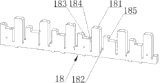
In the present embodiment by size less be called the first hangers 20, larger-size second hangers 19 that is called.On tooling platform panel 1, be provided with tooling base 10, as shown in Figure 3, one end of tooling base 10 is reference edge, along the some quantity along tooling base 10 vertical the first hangers locating template 16, the first hangers locating templates 16 that arrange of laterally evenly being intervally arranged of tooling base 10, arrange according to specific needs.location for the ease of guardrail rectangular tube 23, in the present embodiment, on the tooling base 10 of reference edge end, be fixedly installed end positioning pipe 17, near between adjacent two first hangers locating templates 16 of reference edge, be provided with second a hangers locating template 18, every adjacent two amongs away from three the first hangers locating templates 16 of tooling base 10 other end ends of reference edge are provided with second a hangers locating template 18, the second hangers locating template 18 all is parallel to the first hangers locating template 16, on the tooling base 10 of the second hangers locating template 18 both sides, lower end, be respectively arranged with one be used to limiting the backstay 21 of the second hangers 19 lateral attitudes, on tooling base 10, also be provided with rectangular tube locating template 22, as shown in Figure 4, the structure of the first hangers locating template 16 comprises: the first noumenon, on the first noumenon, evenly be provided with some the first detents 161, one side of each the first detent 161 is installation base 162, opposite side is for clamping gear by face 163, on each installation base 162, be provided with clamping device, each clamping device all can be clamped in the first hangers 20 of correspondence in the first corresponding hangers detent 161, during clamping, the journal stirrup of each the first hangers 20 upwards, and one of them journal stirrup leans on face 163 near the clamping gear of correspondence, the structure of the clamping device in the present embodiment comprises: on the installation base 162 of each the first hangers detent 161 1 side, all be installed with the mounting blocks 164 with through hole, in each through hole, be provided with slide bar 165, the head of every slide bar 165 is provided with the slide block 166 with U-shaped draw-in groove, on slide bar 165 between corresponding slide block 166 and mounting blocks 164, all be set with spring, the equal block of U-shaped draw-in groove on each slide block 166 is in the both sides of one of them journal stirrup of the first hangers 20, and under the effect of spring force, each slide block 166 all can slide by face 163 to the clamping gear of the first hangers detent 161 of correspondence, make the first hangers abut against corresponding clamping gear by on face 163, thereby the first hangers 20 of correspondence is clamped in the first corresponding hangers detent 161, can be shown in Figure 7.as shown in Figure 5, the structure of the second hangers locating template 18 comprises: the second body, on the second body, evenly be provided with some the second hangers positioning boss 181, the both sides of each the second hangers positioning boss 181 are respectively arranged with a block boss 182 and a band keeps off the support rim 183 by face 185, each block boss 182 and support rim 183 form the second hangers draw-in groove 184 respectively with between corresponding the second hangers positioning boss 181, two journal stirrups of the second hangers 19 are put into gear downwards on the second hangers positioning boss 181 of correspondence, and two journal stirrups can be clamped on respectively in the second hangers draw-in groove 184 of corresponding the second hangers positioning boss 181 both sides, as shown in Figure 6, the structure of rectangular tube locating template 22 comprises: the 3rd body, on the 3rd body, evenly be provided with some rectangular tube detents 221, support rim 183 on the first hangers detent 161 on each rectangular tube detent 221 and every the first hangers locating template 16 and every the second hangers locating template 18 is corresponding one by one, the guardrail rectangular tube 23 that is fastened in rectangular tube detent 221 also is located in the first hangers detent 161 corresponding on every the first hangers locating template 16 simultaneously, and the bottom connection of the upper surface of guardrail rectangular tube 23 and the first hangers 20 touches, and guardrail rectangular tube 23 also is bearing on support rim 183 corresponding on every the second hangers locating template 18 simultaneously, its side contacts with a side of the second hangers 19, between tooling platform panel 1 and tooling base 10, also be provided with jacking apparatus, the structure of jacking apparatus comprises: on tooling platform panel 1, be provided with two pairs of jacking cylinders 24, two jacking cylinders 24 of every centering lay respectively at the both sides of tooling base 10, between the piston rod of every pair of jacking cylinder 10, all be fixedly connected with lifting pin 25, described lifting pin 25 is arranged in the below of rectangular tube detent 221 guardrail rectangular tubes 23 on tooling base 10, when the piston rod of two pairs of jacking cylinders 24 upwards extends simultaneously, the guardrail rectangular tube 23 that two lifting pins 25 can complete welding upwards jacking goes out rectangular tube detent 221, can be referring to Fig. 8.Because the other end of the tooling base 10 away from reference edge is provided with two the second hangers locating templates 18, when welding shorter guardrail rectangular tube, only need in these two the second hangers locating templates, near clamping the second hangers 19 on that the second hangers locating template 18 of reference edge, get final product, move inward accordingly the jacking cylinder of the other end, make lifting pin 25 between two jacking cylinders be positioned at the below of slightly short guardrail rectangular tube.
Operation principle of the present utility model is as follows: tooling base 10 is arranged in a working region of tooling platform panel 1, in the present embodiment, take tooling base 10, is arranged in the first working region 11 of tooling platform panel 1 as example and describes.Simultaneously whole clamping tooling is arranged on to the below of welding gun 15 in welding robot 14, and makes the first working region 11 be positioned at the welding post of welding robot 14, territory, secondary service area 12 is positioned at outside the welding post of welding robot 14.while starting welding job, first will need the guardrail rectangular tube 23 that welds to be placed on successively in rectangular tube detent 221, and every guardrail rectangular tube 23 levels are located in the first hangers detent 161 corresponding on every the first hangers locating template 16, and horizontal supporting is on support rim 183 corresponding on every the second hangers locating template 18 simultaneously, and the one end leans the medial surface at the end positioning pipe 17 of tooling base 10 reference edges, then be placed on successively the first hangers 20 on the guardrail rectangular tube 23 in the first hangers detent 161 and the journal stirrup of the first hangers 20 up, the corresponding block of the U-shaped draw-in groove of each the first hangers detent 161 1 side is in the both sides of first hangers 20 one of them journal stirrup, each slide block 166 all can slide by face 163 to the clamping gear of the first hangers detent 161 of correspondence under the effect of spring force, the first hangers 20 is abutted against and clamp gear by on face 163, thereby the first hangers 20 of correspondence is clamped in the first corresponding hangers detent 161, on two second hangers locating templates 18 at tooling base 10 two ends, place successively the second hangers 19 again, during placement, the second hangers 19 is put into gear downwards on the second hangers positioning boss 181, and two journal stirrups that inwardly push the second hangers 19 reduce the spacing of two journal stirrups, and unclamp after snapping in respectively in the second hangers draw-in groove 184, owing on support rim 183, being provided with gear by face 185, gear has limited guardrail rectangular tube 23 along tooling base 10 position longitudinally by face 185, when two journal stirrups of the second hangers 19 open to both sides respectively with the guardrail rectangular tube 23 of one side near, the backstay 21 of the second hangers locating template 18 both sides, lower end is again in the position of laterally having limited the second hangers 19, such the second horizontal and vertical position of hangers 19 just has been completely fixed.guardrail rectangular tube 23 after placing, the first hangers 20, the second hangers 19 is the matrix form proper alignment, solder joint between the three also all is the matrix form proper alignment, the welding gun 15 of controlling welding robot 14 by controller first completes the welding of the pad between the first hangers 20 and guardrail rectangular tube 23 according to putting in order of matrix form, and then put in order the welding of the solder joint between the second hangers 19 and guardrail rectangular tube 23 is completed according to matrix form, welding job in such the first working region 11 has just completed, then drive two pairs of jacking cylinders 24, make its piston rod simultaneously to the top of rising, the guardrail rectangular tube 23 that such two lifting pins 25 just will be welded with the first hangers 20 and the second hangers 19 all upwards jacking go out rectangular tube detent 221, blanking is just very convenient like this.In order to prevent in the jacking process, the stressed flexural deformation of guardrail rectangular tube 23, because being respectively in two pairs of jacking cylinders 24 when trying one's best the symmetric position place at guardrail rectangular tube 20 two ends.when carrying out welding job, the first working region 11 on territory, secondary service area 12, carries out the material loading operation, be about to clamping workpiece that next group need to weld on the tooling base on territory, secondary service area 12, after guardrail rectangular tube 23 welding on the first working region 11 are complete, start servomotor 5, gear 51 on servomotor 5 output shafts rotates, band carry-over bar 6 is moved to the left, the slide rail 3 of tooling platform panel 1 two bottom sides can slide left respectively in the slide block 4 of support foundation 2 both sides like this, replaced to the welding post of welding robot 14 in territory, secondary service area 12, the buffer spring 10 of 12 bottoms, territory, secondary service area is conflicted and on the support foundation 2 of right-hand member, is played buffering and spacing effect, the photoelectric sensor switch 13 of 12 bottoms, territory, secondary service area detects the welding post that territory, secondary service area 12 is positioned at welding robot 14, and send detection signal to controller, controller is given an order to servomotor 5 after receiving this signal, it is cut off self-lock, territory, secondary service area 12 just is locked in the welding post of welding robot 14 like this, again by controller butt welding machine device people 14, carry out the control of welding operation, thereby complete the welding to workpiece on territory, secondary service area 12, on the territory, secondary service area 11 of the welding post of being released welding robot 14 left, carry out simultaneously blanking and the operation of material loading again, the guardrail rectangular tube 23 that has welded that is about on the first working region 11 is removed, and the guardrail rectangular tube 23 that second batch need to be welded, the first hangers 20 and the second hangers 19 clampings are on the tooling base 10 on the first working region 11, after the welding of the workpiece on territory, secondary service area 12 completes, restart servomotor 5, the output shaft reverse rotation driven gear 51 of servomotor 5 rotates, thereby band carry-over bar 6 moves right, replaced again to the welding post of welding robot 14 in the first working region 11, the buffer spring of the first 11 bottoms, working region is conflicted and on the support foundation 2 of left end, is played buffering and spacing effect, the photoelectric sensor switch of the first 11 bottoms, working region detects the welding post that the first working region 11 is positioned at welding robot 14, and send this detection signal to controller, controller is given an order to servomotor 5 after receiving this signal, it is cut off self-lock, such the first working region 11 just is locked in the welding post of welding robot 14, and then by controller butt welding machine device people 14, carry out the control of welding operation, thereby again complete the welding between guardrail rectangular tube 23 on the first working region 11 and the first hangers 20 and the second hangers 19, on the territory, secondary service area 12 of the welding post of being released welding robot 14 to the right, carry out simultaneously blanking and the operation of material loading ground.Above operation constantly repeatedly, can coordinate welding robot 14 to carry out discontinuously hardly welding operation, and, after being provided with photoelectric sensor switch, can be convenient to realize automatic control, has greatly improved the operating efficiency of welding; In addition, the first territory, 11He secondary service area, working region 12 alternately is arranged in the welding post of welding robot 14, makes material loading and blanking all outside the welding post of welding robot 14, carry out, and has so greatly improved the security in the welding job.
On bracing frame, also be provided with in the present embodiment manual transposer, when electronic transposer is out of order, can carry out manual ex-situ operations.During manual ex-situ operations, servomotor 5 is in off-position, opens the parking brake on servomotor 5, makes the output shaft of servomotor 5 in the situation that there is the external force drive to rotate.As shown in Figure 1, this moment, the first working region 11 was positioned at the welding post of welding robot 14, inhaled the inboard that iron 9 is attracted to the first switching regulator magnet base 7.when needs replace, close the electromagnetic switch on the first switching regulator magnet base 7, promote tooling platform panel 1 left, the gear 51 that the tooth bar 6 of tooling platform panel 1 bottom is driven on the output shaft of servomotors 5 rotates, the slide rail 3 of tooling platform panel 1 two bottom sides slides left respectively in the slide block 4 of support foundation 2 both sides simultaneously, such the first working region 11 is released the welding post of welding robot 14 gradually left, territory, secondary service area 12 is advanced in the welding post of welding robot 14 gradually, when suction iron 9 moves to second switch formula magnet base 8 from the first switching regulator magnet base 7, territory, secondary service area 12 is positioned at the welding post of welding robot 14 fully, the buffer spring 10 of 12 bottoms, territory, secondary service area is conflicted and on the support foundation 2 of right-hand member, is played buffering and spacing effect, open the electromagnetic switch on second switch formula magnet base 8, make second switch formula magnet base 8 produce magnetic force, and will inhale iron 9 and firmly be adsorbed on its inboard, then close the parking brake on servomotor 5, territory, secondary service area 12 just is locked in the welding post of welding robot 14 like this, when being replaced again in the first working region 11 in the welding post of welding robot 14 time, close the magnetic switch on second switch formula magnet base 8, open the parking brake on servomotor 5, promote tooling platform panel 1 to the right, the gear 51 that the tooth bar 6 of tooling platform panel 1 bottom is oppositely driven on the output shaft of servomotor 5 rotates, the slide rail 3 of tooling platform panel 1 two bottom sides slides to the right respectively in the slide block 4 of support foundation 2 both sides simultaneously, the welding post of welding robot 14 is released in territory, secondary service area 12 gradually to the right like this, the first working region 11 is advanced in the welding post of welding robot gradually, when suction iron 9 moves to the first switching regulator magnet base 7 from second switch formula magnet base 8, the first working region 11 is positioned at the welding post of welding robot 14 fully, the buffer spring of the first 11 bottoms, working region is conflicted on the support foundation 2 of left end and is played buffering and spacing effect, open again the magnetic switch on the first switching regulator magnet base 7 this moment, make its generation magnetic force will inhale iron and firmly be adsorbed on its inboard, and close the parking brake of servomotor 5, such the first working region 11 is locked in again in the welding post of welding robot 14, manually identical in the process of the welding in the ex-situ operations process, material loading, blanking and electronic transposition process, repeat no more.Above operation repeats constantly to realize that the first territory, 11He secondary service area, working region 12 constantly alternately is positioned at the conversion operations of the welding post of welding robot 14 mutually, thereby coordinate welding robot 14 to carry out hardly welding operation discontinuously, welding job efficiency improves greatly.On the first territory, 11He secondary service area, working region, can identical or different clamping tooling be installed according to need of production.
Claims (5)
1. guardrail of medical bed rectangular tube and hangers weld the clamping tooling of use, comprise: bracing frame, on bracing frame, be provided with tooling base, one end of tooling base is reference edge, it is characterized in that: on the tooling base of reference edge end, be fixedly installed the end positioning pipe, some the first hangers locating templates that vertically arrange along tooling base that laterally evenly are intervally arranged along tooling base, near between adjacent two first hangers locating templates of reference edge, be provided with second a hangers locating template, every adjacent two amongs away from three the first hangers locating templates of the tooling base other end end of reference edge are provided with second a hangers locating template, the second hangers locating template all is parallel to the first hangers locating template, on the tooling base of the second both sides, hangers locating template lower end, be respectively arranged with one be used to limiting the backstay of the second hangers lateral attitude, on tooling base, also be provided with the rectangular tube locating template, the structure of the first hangers locating template comprises: the first noumenon, on the first noumenon, evenly be provided with some the first detents, one side of each the first detent is installation base, opposite side is for clamping gear by face, on each installation base, be provided with clamping device, each clamping device all can be clamped in the first hangers of correspondence in the first corresponding hangers detent, during clamping, the journal stirrup of each the first hangers upwards, and one of them journal stirrup leans on face near the clamping gear of correspondence, the structure of the second hangers locating template comprises: the second body, on the second body, evenly be provided with some the second hangers positioning boss, the both sides of each the second hangers positioning boss are respectively arranged with a block boss and a band keeps off the support rim by face, each block boss and support rim form the second hangers draw-in groove respectively with between corresponding the second hangers positioning boss, and two journal stirrups of the second hangers are put into gear downwards on the second hangers positioning boss of correspondence and two journal stirrups can be clamped on respectively in the second hangers draw-in groove of both sides, the structure of described rectangular tube locating template comprises: the 3rd body, on the 3rd body, evenly be provided with some rectangular tube detents, support rim on the first hangers detent on each rectangular tube detent and every the first hangers locating template and every the second hangers locating template is corresponding one by one, the guardrail rectangular tube that is fastened in the rectangular tube detent also is located in the first hangers detent corresponding on every the first hangers locating template simultaneously, and the upper surface of guardrail rectangular tube touches with the bottom connection of corresponding the first hangers, and the guardrail rectangular tube also is bearing on support rim corresponding on every the second hangers locating template simultaneously, the side of guardrail rectangular tube contacts with the side of corresponding the second hangers, between bracing frame and tooling base, also be provided with jacking apparatus, the guardrail rectangular tube that jacking apparatus can the complete welding jacking that makes progress goes out the rectangular tube detent.
2. guardrail of medical bed rectangular tube according to claim 1 and hangers weld the clamping tooling of use, it is characterized in that: the structure of described clamping device comprises: on the installation base of each the first hangers detent one side, all be installed with the mounting blocks with through hole, in each through hole, be provided with slide bar, the head of every slide bar is provided with the slide block with U-shaped draw-in groove, on slide bar between corresponding slide block and mounting blocks, all be set with spring, the equal block of U-shaped draw-in groove on each slide block is in the both sides of one of them journal stirrup of the first hangers of correspondence, and under the effect of spring force, each slide block all can move by face to the clamping gear of correspondence, make the first corresponding hangers abut against corresponding clamping gear by on face, thereby the first hangers of correspondence is clamped in the first corresponding hangers detent.
3. guardrail of medical bed rectangular tube according to claim 1 and 2 and hangers weld the clamping tooling of use, it is characterized in that: the structure of described jacking apparatus comprises: on bracing frame, be provided with two pairs of jacking cylinders, two jacking cylinders in the every pair of jacking cylinder lay respectively at the both sides of tooling base, between the piston rod of every pair of jacking cylinder, all be fixedly connected with lifting pin, described lifting pin is arranged in the below of rectangular tube detent guardrail rectangular tube on tooling base, when the piston rod of two pairs of jacking cylinders upwards extends simultaneously, the guardrail rectangular tube that two lifting pins can the complete welding jacking that makes progress goes out the rectangular tube detent.
4. guardrail of medical bed rectangular tube according to claim 1 and 2 and hangers weld the clamping tooling of use, it is characterized in that: the structure of described bracing frame comprises: the tooling platform panel, the tooling platform panel is bearing on support foundation, on the tooling platform panel, be provided with the first working region and territory, secondary service area, between support foundation and tooling platform panel, be provided with electronic transposer, the structure of described electronic transposer is: the two bottom sides of tooling platform panel is fixedly installed respectively slide rail, the both sides, top of support foundation are fixedly installed respectively slide block, slide rail is corresponding being bearing in the slide block of both sides, support foundation top respectively, servomotor with parking brake is installed on support foundation, on the output shaft of servomotor, be provided with gear, the tooth bar that is meshed with gear is fixedly mounted on the bottom of tooling platform panel, under the driving of servomotor, the slide rail of tooling platform panel two bottom sides can slidably reciprocate respectively in the slide block of support foundation both sides, and can make the first working region, the territory, secondary service area alternately is positioned at welding post, between support foundation and tooling platform panel, also be provided with manual transposer, its concrete structure comprises: in support foundation one side, be separately installed with the first switching regulator magnet base and second switch formula magnet base, can by the suction ferropexy of first, second switching regulator magnet base absorption, be arranged on the side of the tooling platform panel between two switching regulator magnet bases respectively, when suction iron moves to another switching regulator magnet base from the first switching regulator magnet base, realize that the first working region, territory, secondary service area alternately are positioned at the conversion operations of welding post mutually.
5. guardrail of medical bed rectangular tube according to claim 4 and hangers weld the clamping tooling of use, it is characterized in that: the two ends, bottom in the first working region and territory, secondary service area are provided with buffer spring and photoelectric sensor switch respectively, when trade-off is realized in two working regions on the tooling platform panel, described buffer spring can be conflicted respectively on the support foundation of a corresponding end, and described photoelectric sensor switch can detect respectively corresponding working region and alternately is positioned at the state of welding post and sends detection signal.
Priority Applications (1)
| Application Number | Priority Date | Filing Date | Title |
|---|---|---|---|
| CN2013203155626U CN203292751U (en) | 2013-06-04 | 2013-06-04 | Clamping tool for welding guard rail rectangular tubes and hanging lugs on medical bed |
Applications Claiming Priority (1)
| Application Number | Priority Date | Filing Date | Title |
|---|---|---|---|
| CN2013203155626U CN203292751U (en) | 2013-06-04 | 2013-06-04 | Clamping tool for welding guard rail rectangular tubes and hanging lugs on medical bed |
Publications (1)
| Publication Number | Publication Date |
|---|---|
| CN203292751U true CN203292751U (en) | 2013-11-20 |
Family
ID=49568789
Family Applications (1)
| Application Number | Title | Priority Date | Filing Date |
|---|---|---|---|
| CN2013203155626U Withdrawn - After Issue CN203292751U (en) | 2013-06-04 | 2013-06-04 | Clamping tool for welding guard rail rectangular tubes and hanging lugs on medical bed |
Country Status (1)
| Country | Link |
|---|---|
| CN (1) | CN203292751U (en) |
Cited By (6)
| Publication number | Priority date | Publication date | Assignee | Title |
|---|---|---|---|---|
| CN103331540A (en) * | 2013-06-04 | 2013-10-02 | 张家港市永发机器人科技有限公司 | Clamping tool for welding rectangular guardrail tubes and suspension loops of medical bed |
| CN106378563A (en) * | 2015-07-31 | 2017-02-08 | 特变电工沈阳变压器集团有限公司 | Converter transformer pulling plate welding clamp and welding method thereof |
| CN109365964A (en) * | 2018-10-29 | 2019-02-22 | 甘肃酒钢集团宏兴钢铁股份有限公司 | A kind of detachable media box otic placode positioning mold and otic placode fixed-position welding method |
| CN111673371A (en) * | 2020-07-01 | 2020-09-18 | 彭博 | Pneumatic clamping automatic welding equipment for vertical pipe guardrail |
| CN113510020A (en) * | 2021-05-31 | 2021-10-19 | 东风商用车有限公司 | Two-piece molybdenum spraying fixture for gearbox synchronization ring and its clamping structure and spraying method |
| CN115488657A (en) * | 2022-09-22 | 2022-12-20 | 江苏太平洋精锻科技股份有限公司 | Metal cutting positioning tool convenient for station conversion |
-
2013
- 2013-06-04 CN CN2013203155626U patent/CN203292751U/en not_active Withdrawn - After Issue
Cited By (8)
| Publication number | Priority date | Publication date | Assignee | Title |
|---|---|---|---|---|
| CN103331540A (en) * | 2013-06-04 | 2013-10-02 | 张家港市永发机器人科技有限公司 | Clamping tool for welding rectangular guardrail tubes and suspension loops of medical bed |
| CN103331540B (en) * | 2013-06-04 | 2015-03-25 | 张家港市永发机器人科技有限公司 | Clamping tool for welding rectangular guardrail tubes and suspension loops of medical bed |
| CN106378563A (en) * | 2015-07-31 | 2017-02-08 | 特变电工沈阳变压器集团有限公司 | Converter transformer pulling plate welding clamp and welding method thereof |
| CN109365964A (en) * | 2018-10-29 | 2019-02-22 | 甘肃酒钢集团宏兴钢铁股份有限公司 | A kind of detachable media box otic placode positioning mold and otic placode fixed-position welding method |
| CN109365964B (en) * | 2018-10-29 | 2023-10-24 | 甘肃酒钢集团宏兴钢铁股份有限公司 | Detachable medium box lug plate positioning die and lug plate positioning welding method |
| CN111673371A (en) * | 2020-07-01 | 2020-09-18 | 彭博 | Pneumatic clamping automatic welding equipment for vertical pipe guardrail |
| CN113510020A (en) * | 2021-05-31 | 2021-10-19 | 东风商用车有限公司 | Two-piece molybdenum spraying fixture for gearbox synchronization ring and its clamping structure and spraying method |
| CN115488657A (en) * | 2022-09-22 | 2022-12-20 | 江苏太平洋精锻科技股份有限公司 | Metal cutting positioning tool convenient for station conversion |
Similar Documents
| Publication | Publication Date | Title |
|---|---|---|
| CN103331540B (en) | Clamping tool for welding rectangular guardrail tubes and suspension loops of medical bed | |
| CN104889708B (en) | Condenser elastic step nut fitting machine | |
| CN104384931A (en) | Machining workstation of flange-type sleeve | |
| CN103659130B (en) | Axle bottom plate automatic positioning welding tooling equipment | |
| CN103231617A (en) | Manipulator of engraving and milling machine | |
| CN201940771U (en) | Hanging disc type pipeline flange grouping machine | |
| CN103231618A (en) | Automatic system of engraving and milling machine and operating method thereof | |
| CN203254100U (en) | Welding positioning device of trench surface plate | |
| CN106216989B (en) | A kind of seat frame automatic assembling | |
| CN203738214U (en) | Automatic movable welding device | |
| CN204075654U (en) | A kind of core of membrane type gas meter body vertical shaft pressing machine | |
| CN204160172U (en) | The machining operations station of flange form sleeve | |
| CN104707879A (en) | Automatic digital straightening machine of trailer axle | |
| CN208644595U (en) | Screw automatic assembling machine | |
| CN201825566U (en) | Automatic barreled water stacker | |
| CN204189884U (en) | Battery clamping positioning mechanism | |
| CN203411063U (en) | Trolley material-loading device | |
| CN206169572U (en) | Automatic kludge of seat frame | |
| CN204976081U (en) | Sunroof rail double -end chamfer tool | |
| CN110883491B (en) | Self-adaptive coordination device suitable for large-size blade type plate and use method thereof | |
| CN203991852U (en) | A kind of Pneumatic bending machine | |
| CN203992842U (en) | A kind of storage crossbeam P type beam column card multiple gun special welding equipment | |
| CN202591895U (en) | Swinging and overlapping tool for supporting leg housing of automobile crane | |
| CN205802434U (en) | A kind of scraps of paper conveyer device of paper cup making machine | |
| CN204221280U (en) | Tetrahedron is merged automation and is welded assembly |
Legal Events
| Date | Code | Title | Description |
|---|---|---|---|
| C14 | Grant of patent or utility model | ||
| GR01 | Patent grant | ||
| AV01 | Patent right actively abandoned |
Granted publication date: 20131120 Effective date of abandoning: 20150325 |
|
| RGAV | Abandon patent right to avoid regrant |