CN203288841U - Electric connector - Google Patents
Electric connector Download PDFInfo
- Publication number
- CN203288841U CN203288841U CN2013202073493U CN201320207349U CN203288841U CN 203288841 U CN203288841 U CN 203288841U CN 2013202073493 U CN2013202073493 U CN 2013202073493U CN 201320207349 U CN201320207349 U CN 201320207349U CN 203288841 U CN203288841 U CN 203288841U
- Authority
- CN
- China
- Prior art keywords
- electric connector
- insulating body
- mainboard
- insulation shell
- embedded
- Prior art date
- Legal status (The legal status is an assumption and is not a legal conclusion. Google has not performed a legal analysis and makes no representation as to the accuracy of the status listed.)
- Expired - Lifetime
Links
Images


Classifications
-
- H—ELECTRICITY
- H01—ELECTRIC ELEMENTS
- H01R—ELECTRICALLY-CONDUCTIVE CONNECTIONS; STRUCTURAL ASSOCIATIONS OF A PLURALITY OF MUTUALLY-INSULATED ELECTRICAL CONNECTING ELEMENTS; COUPLING DEVICES; CURRENT COLLECTORS
- H01R13/00—Details of coupling devices of the kinds covered by groups H01R12/70 or H01R24/00 - H01R33/00
- H01R13/46—Bases; Cases
- H01R13/516—Means for holding or embracing insulating body, e.g. casing, hoods
-
- H—ELECTRICITY
- H01—ELECTRIC ELEMENTS
- H01R—ELECTRICALLY-CONDUCTIVE CONNECTIONS; STRUCTURAL ASSOCIATIONS OF A PLURALITY OF MUTUALLY-INSULATED ELECTRICAL CONNECTING ELEMENTS; COUPLING DEVICES; CURRENT COLLECTORS
- H01R13/00—Details of coupling devices of the kinds covered by groups H01R12/70 or H01R24/00 - H01R33/00
- H01R13/46—Bases; Cases
- H01R13/52—Dustproof, splashproof, drip-proof, waterproof, or flameproof cases
- H01R13/521—Sealing between contact members and housing, e.g. sealing insert
-
- H—ELECTRICITY
- H01—ELECTRIC ELEMENTS
- H01R—ELECTRICALLY-CONDUCTIVE CONNECTIONS; STRUCTURAL ASSOCIATIONS OF A PLURALITY OF MUTUALLY-INSULATED ELECTRICAL CONNECTING ELEMENTS; COUPLING DEVICES; CURRENT COLLECTORS
- H01R12/00—Structural associations of a plurality of mutually-insulated electrical connecting elements, specially adapted for printed circuits, e.g. printed circuit boards [PCB], flat or ribbon cables, or like generally planar structures, e.g. terminal strips, terminal blocks; Coupling devices specially adapted for printed circuits, flat or ribbon cables, or like generally planar structures; Terminals specially adapted for contact with, or insertion into, printed circuits, flat or ribbon cables, or like generally planar structures
- H01R12/70—Coupling devices
- H01R12/71—Coupling devices for rigid printing circuits or like structures
- H01R12/72—Coupling devices for rigid printing circuits or like structures coupling with the edge of the rigid printed circuits or like structures
- H01R12/722—Coupling devices for rigid printing circuits or like structures coupling with the edge of the rigid printed circuits or like structures coupling devices mounted on the edge of the printed circuits
- H01R12/724—Coupling devices for rigid printing circuits or like structures coupling with the edge of the rigid printed circuits or like structures coupling devices mounted on the edge of the printed circuits containing contact members forming a right angle
-
- H—ELECTRICITY
- H01—ELECTRIC ELEMENTS
- H01R—ELECTRICALLY-CONDUCTIVE CONNECTIONS; STRUCTURAL ASSOCIATIONS OF A PLURALITY OF MUTUALLY-INSULATED ELECTRICAL CONNECTING ELEMENTS; COUPLING DEVICES; CURRENT COLLECTORS
- H01R13/00—Details of coupling devices of the kinds covered by groups H01R12/70 or H01R24/00 - H01R33/00
- H01R13/46—Bases; Cases
- H01R13/52—Dustproof, splashproof, drip-proof, waterproof, or flameproof cases
- H01R13/5219—Sealing means between coupling parts, e.g. interfacial seal
-
- H—ELECTRICITY
- H01—ELECTRIC ELEMENTS
- H01R—ELECTRICALLY-CONDUCTIVE CONNECTIONS; STRUCTURAL ASSOCIATIONS OF A PLURALITY OF MUTUALLY-INSULATED ELECTRICAL CONNECTING ELEMENTS; COUPLING DEVICES; CURRENT COLLECTORS
- H01R13/00—Details of coupling devices of the kinds covered by groups H01R12/70 or H01R24/00 - H01R33/00
- H01R13/648—Protective earth or shield arrangements on coupling devices, e.g. anti-static shielding
- H01R13/658—High frequency shielding arrangements, e.g. against EMI [Electro-Magnetic Interference] or EMP [Electro-Magnetic Pulse]
- H01R13/6591—Specific features or arrangements of connection of shield to conductive members
- H01R13/6594—Specific features or arrangements of connection of shield to conductive members the shield being mounted on a PCB and connected to conductive members
Landscapes
- Details Of Connecting Devices For Male And Female Coupling (AREA)
- Connector Housings Or Holding Contact Members (AREA)
Abstract
一种电连接器,包括绝缘本体、若干容纳于绝缘本体内的导电端子、包围绝缘本体而形成容置空间的金属遮蔽壳体及套设于金属遮蔽壳体外的绝缘壳体。电连接器还包括金属件,所述金属件于容置空间的上方及左右两侧三个方向镶埋于绝缘壳体。摇摆测试中,本电连接器能够承受较大的插入力,避免了金属遮蔽壳体断裂的风险。

An electrical connector includes an insulating body, a plurality of conductive terminals accommodated in the insulating body, a metal shielding shell surrounding the insulating body to form an accommodating space, and an insulating shell sleeved outside the metal shielding shell. The electrical connector also includes a metal piece embedded in the insulating shell in three directions above the accommodating space and on the left and right sides. In the swing test, the electrical connector can withstand a large insertion force, avoiding the risk of breaking the metal shielding shell.
Description
【技术领域】【Technical field】
本实用新型涉及一种电连接器,尤其涉及一种结构稳定的电连接器。 The utility model relates to an electric connector, in particular to an electric connector with a stable structure.
【背景技术】【Background technique】
USB规格是由Intel(英特尔)、NEC(日本电气株式会社)、Compaq(康柏)、DEC(美国数字设备公司)、IBM(国际商业机器公司)、Microsoft(微软)、Northern Telecom(北方电信公司)联合制定的,现在已广泛应用于各种电子设备上。USB插座连接器设置于设备内,并且形成有连通外部的容置空间,用于容纳USB插头连接器。USB插座连接器包括绝缘本体、若干容纳于绝缘本体内的导电端子及包围绝缘本体而形成容置空间的金属遮蔽壳体。USB插座连接器通常需要经过摇摆测试以检验其稳定性。摇摆测试中,当插入力过大时,极易造成金属遮蔽壳体受到较大的冲击而断裂。 The USB specification is developed by Intel (Intel), NEC (Japan Electric Corporation), Compaq (Compaq), DEC (Digital Equipment Corporation of America), IBM (International Business Machines Corporation), Microsoft (Microsoft), Northern Telecom (Northern Telecom Corporation) ) Jointly formulated, it has been widely used in various electronic devices. The USB socket connector is arranged in the device, and forms an accommodating space communicating with the outside for accommodating the USB plug connector. The USB socket connector includes an insulating body, a plurality of conductive terminals accommodated in the insulating body, and a metal shielding shell surrounding the insulating body to form an accommodating space. USB receptacle connectors usually need to undergo a rocking test to verify their stability. In the swing test, when the insertion force is too large, it is very easy to cause the metal shielding shell to break due to a large impact.
因此,确有必要提供一种能克服前述缺陷的电连接器。 Therefore, it is necessary to provide an electrical connector capable of overcoming the aforementioned drawbacks.
【实用新型内容】【Content of utility model】
本实用新型的目的在于提供一种结构稳定的电连接器。 The purpose of the utility model is to provide an electrical connector with a stable structure.
为达成上述目的,本实用新型采用如下技术方案:一种电连接器,包括绝缘本体、若干容纳于绝缘本体内的导电端子、包围绝缘本体而形成容置空间的金属遮蔽壳体及套设于金属遮蔽壳体外的绝缘壳体,电连接器还包括金属件,所述金属件于容置空间的上方及左右两侧三个方向镶埋于绝缘壳体。 In order to achieve the above purpose, the utility model adopts the following technical solutions: an electrical connector, including an insulating body, a number of conductive terminals accommodated in the insulating body, a metal shielding shell that surrounds the insulating body to form an accommodating space, and is sheathed in the The metal shields the insulating shell outside the shell, and the electrical connector also includes metal parts embedded in the insulating shell in three directions above the accommodating space and on the left and right sides.
进一步地,所述金属件包括主板及自主板两对侧同向弯折延伸的两侧板,所述绝缘壳体包括上表面、与上表面相对的安装面及连接上表面和安装面的两侧面,主板及侧板分别镶埋于上表面及侧面。 Further, the metal part includes a main board and two side plates bent and extended in the same direction on two opposite sides of the main board, and the insulating housing includes an upper surface, an installation surface opposite to the upper surface, and two connecting upper surface and the installation surface. The side, the main board and the side panels are respectively embedded in the upper surface and the side.
进一步地,所述主板设有在镶埋成型过程中令塑胶流入的通孔。 Further, the main board is provided with a through hole for plastic to flow in during the embedded molding process.
进一步地,所述绝缘壳体包括前部及后部,后部的两侧分别设有高度低于上表面的凹部,主板包括分布于侧板两侧的延伸柱,延伸柱镶埋于后部且延伸柱的顶面与凹部的顶面平齐。 Further, the insulating housing includes a front part and a rear part, and the two sides of the rear part are respectively provided with concave parts whose height is lower than the upper surface, and the main board includes extension columns distributed on both sides of the side plates, and the extension columns are embedded in the rear part And the top surface of the extension column is flush with the top surface of the concave part.
进一步地,所述延伸柱系冲压成型后切掉料带而成。 Further, the extension column is formed by cutting off the strip after stamping.
进一步地,电连接器包括套设于前部上的防水圈。 Further, the electrical connector includes a waterproof ring sheathed on the front part.
进一步地,所述绝缘本体具有点胶形成的防水板,所述导电端子包括焊接部,所述焊接部穿出防水板。 Further, the insulating body has a waterproof plate formed by dispensing glue, the conductive terminal includes a welding portion, and the welding portion passes through the waterproof plate.
进一步地,所述侧板包括连接于主板上的窄部及自窄部向下一体延伸的宽部,所述宽部上开设有在镶埋成型过程中令塑胶流入的开口。 Further, the side plate includes a narrow portion connected to the main board and a wide portion integrally extending downward from the narrow portion, the wide portion is provided with an opening for plastic to flow in during the embedded molding process.
进一步地,所述窄部和宽部连接处形成在镶埋成型过程中令塑胶包围其上的肩部。 Further, the junction of the narrow portion and the wide portion forms a shoulder portion that is surrounded by plastic during the embedding molding process.
进一步地,所述侧板延伸出绝缘壳体的安装面。 Further, the side plate extends beyond the installation surface of the insulating housing.
与现有技术相比,本实用新型具有如下有益效果:金属件于容置空间的上方及左右两侧三个方向镶埋于绝缘壳体而保证了金属遮蔽壳体的稳定性,从而在摇摆测试中,电连接器能够承受较大的插入力,避免了金属遮蔽壳体断裂的风险。 Compared with the prior art, the utility model has the following beneficial effects: the metal parts are embedded in the insulating shell in three directions above the accommodating space and on the left and right sides, thereby ensuring the stability of the metal shielding shell, thereby During the test, the electrical connector can withstand a large insertion force, avoiding the risk of breaking the metal shielding shell.
【附图说明】【Description of drawings】
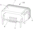
图1是本实用新型电连接器的立体组合图。 Fig. 1 is a three-dimensional assembled view of the electrical connector of the present invention.
图2是本实用新型电连接器另一角度的立体组合图。 Fig. 2 is a three-dimensional assembled view of another angle of the electric connector of the present invention.
图3是本实用新型电连接器的立体分解图。 Fig. 3 is a three-dimensional exploded view of the electrical connector of the present invention.
图4是本实用新型电连接器另一角度的立体分解图。 Fig. 4 is a three-dimensional exploded view from another angle of the electrical connector of the present invention.
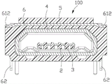
图5是本实用新型电连接器沿图1中A-A线的剖视图。 Fig. 5 is a sectional view of the electrical connector of the present invention along line A-A in Fig. 1 .
图6是本实用新型电连接器沿图1中B-B线的剖视图。 Fig. 6 is a sectional view of the electrical connector of the present invention along line B-B in Fig. 1 .
【主要组件符号说明】 [Description of main component symbols]
如下具体实施方式将结合上述附图进一步说明本实用新型。 The following specific embodiments will further illustrate the utility model in conjunction with the above-mentioned accompanying drawings.
【具体实施方式】【Detailed ways】
请参照图1至图6所示,本实用新型电连接器100安装于电路板(未图示)以与对接连接器(未图示)对接,包括绝缘本体2、若干容纳于绝缘本体2内的导电端子3、包围绝缘本体2而形成容置空间40的金属遮蔽壳体4、套设于金属遮蔽壳体4外的绝缘壳体5及镶埋成型于绝缘壳体5的金属件6。容置空间40前端设有供对接连接器插入的插入口401。
Please refer to Figures 1 to 6, the
绝缘本体2包括基部21及自基部21向前延伸的舌板22。所述导电端子3包括固持于基部21内的固持部31、自固持部31向前延伸至凸露于舌板22上方的接触部32及自固持部31向后延伸出绝缘本体2的焊接部33。
The
金属遮蔽壳体4为冲压形成,其包括主体部41及自主体部41向后折弯形成的一对插板部42。
The
绝缘壳体5为框状,包括靠近插入口401的前部51及远离插入口401的后部52。所述前部51和后部52形成前低后高的台阶状。所述金属件6镶埋成型于绝缘壳体5的后部52。所述绝缘壳体5包括上表面521、与上表面521相对的安装面522及连接上表面521和安装面522的两侧面523。后部52的两侧分别设有高度低于上表面521的凹部524。
The
优选实施方式中,绝缘壳体5的前部51上套设防水圈7,绝缘本体2的基部21的后端面也即绝缘本体2的后端面点胶形成有防水板8。所述防水板8完全封闭绝缘本体2于绝缘壳体5内,以达成防水功效。所述焊接部33穿出防水板8,用以焊接于电路板上。
In a preferred embodiment, a
金属件6为“ㄇ”形,包括主板61及自主板61两对侧同向弯折延伸的两侧板62。所述主板61开设有通孔611,用于镶埋成型过程中塑胶流入通孔611,从而绝缘壳体5和金属件6紧密结合。主板61包括分布于侧板62两侧的延伸柱612。所述延伸柱612镶埋于后部52,亦用于绝缘壳体5和金属件6的紧密结合。所述延伸柱612的顶面与凹部524的顶面平齐,从而在注塑的过程中,模具抵住所述延伸柱612用于定位。冲压成型金属件6前,所述延伸柱612连接至料带,即延伸柱612系冲压成型后切掉料带而成。所述侧板62包括连接于主板61上的窄部621及自窄部621向下一体延伸的宽部622。窄部621和宽部622连接处形成肩部623。所述宽部622上开设有开口6221。镶埋成型过程中塑胶流入开口6221且塑胶包围肩部623,从而绝缘壳体5和金属件6紧密结合。所述侧板62镶埋于侧面523且延伸出绝缘壳体5的安装面522,从而侧板62插板于电路板上。电连接器100通过焊接部33焊接、金属遮蔽壳体4的插板部42及金属件6的侧板62插板两种方式结合于电路板,保证了电连接器100和电路板之间的稳定性。金属件6于容置空间40的上方及左右两侧三个方向镶埋于绝缘壳体5而保证了金属遮蔽壳体4的稳定性,从而在摇摆测试中,电连接器100能够承受较大的插入力,避免了金属遮蔽壳体4断裂的风险。
The
以上所述仅为本实用新型的一种实施方式,不是唯一的实施方式,本领域普通技术人员通过阅读本实用新型说明书而对本实用新型技术方案采取的任何等效的变化,均为本实用新型的权利要求所涵盖。 The above is only one embodiment of the utility model, not the only implementation. Any equivalent changes to the technical solution of the utility model adopted by those of ordinary skill in the art by reading the specification of the utility model are all changes of the utility model. covered by the claims.
Claims (10)
Priority Applications (2)
| Application Number | Priority Date | Filing Date | Title |
|---|---|---|---|
| CN2013202073493U CN203288841U (en) | 2013-04-23 | 2013-04-23 | Electric connector |
| US14/258,226 US9112296B2 (en) | 2013-04-23 | 2014-04-22 | Electrical connector with high reliability |
Applications Claiming Priority (1)
| Application Number | Priority Date | Filing Date | Title |
|---|---|---|---|
| CN2013202073493U CN203288841U (en) | 2013-04-23 | 2013-04-23 | Electric connector |
Publications (1)
| Publication Number | Publication Date |
|---|---|
| CN203288841U true CN203288841U (en) | 2013-11-13 |
Family
ID=49545187
Family Applications (1)
| Application Number | Title | Priority Date | Filing Date |
|---|---|---|---|
| CN2013202073493U Expired - Lifetime CN203288841U (en) | 2013-04-23 | 2013-04-23 | Electric connector |
Country Status (2)
| Country | Link |
|---|---|
| US (1) | US9112296B2 (en) |
| CN (1) | CN203288841U (en) |
Cited By (8)
| Publication number | Priority date | Publication date | Assignee | Title |
|---|---|---|---|---|
| CN103972719A (en) * | 2014-05-06 | 2014-08-06 | 连展科技电子(昆山)有限公司 | Waterproof electric connector |
| CN104332788A (en) * | 2014-05-30 | 2015-02-04 | 连展科技电子(昆山)有限公司 | All-in-one socket connector |
| CN104795698A (en) * | 2015-05-05 | 2015-07-22 | 昆山嘉华精密工业有限公司 | Electric connector and manufacturing method thereof |
| EP2960998A1 (en) * | 2014-06-27 | 2015-12-30 | Samsung Electronics Co., Ltd | Connector device and electronic device with the same |
| CN105470697A (en) * | 2015-04-02 | 2016-04-06 | 富士康(昆山)电脑接插件有限公司 | Electrical connector and manufacturing method thereof |
| CN107240808A (en) * | 2016-11-14 | 2017-10-10 | 富士康(昆山)电脑接插件有限公司 | Electric connector and its manufacture method |
| CN107465015A (en) * | 2016-06-06 | 2017-12-12 | 富士康(昆山)电脑接插件有限公司 | Electric connector and its manufacture method |
| CN110364864A (en) * | 2018-04-11 | 2019-10-22 | 富士康(昆山)电脑接插件有限公司 | Electric connector |
Families Citing this family (22)
| Publication number | Priority date | Publication date | Assignee | Title |
|---|---|---|---|---|
| US9356400B2 (en) * | 2013-07-19 | 2016-05-31 | Foxconn Interconnect Technology Limited | Flippable electrical connector |
| CN203631803U (en) * | 2013-08-21 | 2014-06-04 | 富士康(昆山)电脑接插件有限公司 | Socket connector |
| CN104577417B (en) * | 2013-10-21 | 2017-05-24 | 富士康(昆山)电脑接插件有限公司 | Electric connector |
| CN105490095A (en) * | 2014-09-16 | 2016-04-13 | 凡甲电子(苏州)有限公司 | Electric connector and electric connector combination |
| CN204243389U (en) * | 2014-12-12 | 2015-04-01 | 富士康(昆山)电脑接插件有限公司 | Micro coaxial cable connector assembly |
| CN104538782B (en) * | 2014-12-19 | 2023-05-05 | 连展科技电子(昆山)有限公司 | Waterproof socket electric connector |
| CN105449443B (en) * | 2015-02-11 | 2018-03-06 | 富士康(昆山)电脑接插件有限公司 | Electric connector and its manufacture method |
| JP6053883B1 (en) * | 2015-07-29 | 2016-12-27 | 株式会社エクセル電子 | Waterproof connector and electronic device |
| US9425560B1 (en) * | 2015-10-15 | 2016-08-23 | Cheng Uei Precision Industry Co., Ltd. | Electrical connector |
| CN205376880U (en) * | 2015-12-03 | 2016-07-06 | 连展科技(深圳)有限公司 | Electric connector |
| CN105703144B (en) * | 2016-01-14 | 2020-10-30 | 富士康(昆山)电脑接插件有限公司 | Electric connector and assembling method thereof |
| CN106374249B (en) * | 2016-04-01 | 2019-06-28 | 富士康(昆山)电脑接插件有限公司 | Electric connector and its manufacturing method |
| CN205790641U (en) * | 2016-05-06 | 2016-12-07 | 富士康(昆山)电脑接插件有限公司 | Electric connector |
| JP2017208193A (en) * | 2016-05-17 | 2017-11-24 | 日本圧着端子製造株式会社 | Waterproof connector |
| CN206595424U (en) * | 2016-10-05 | 2017-10-27 | 番禺得意精密电子工业有限公司 | Connector |
| CN206532925U (en) * | 2016-11-22 | 2017-09-29 | 番禺得意精密电子工业有限公司 | Electric connector |
| CN108123277B (en) * | 2016-11-29 | 2019-12-27 | 富士康(昆山)电脑接插件有限公司 | Electrical connector |
| JP6890779B2 (en) * | 2017-03-30 | 2021-06-18 | ミツミ電機株式会社 | connector |
| CN110071391B (en) * | 2018-01-23 | 2022-04-22 | 富士康(昆山)电脑接插件有限公司 | Electrical connector |
| CN207781990U (en) * | 2018-01-23 | 2018-08-28 | 富誉电子科技(淮安)有限公司 | Electric coupler component |
| CN111009777B (en) * | 2018-10-08 | 2023-01-24 | 富顶精密组件(深圳)有限公司 | Electric connector and manufacturing method thereof |
| TWM595905U (en) * | 2019-11-28 | 2020-05-21 | 連展科技股份有限公司 | Connector structure |
Family Cites Families (11)
| Publication number | Priority date | Publication date | Assignee | Title |
|---|---|---|---|---|
| JP4581281B2 (en) | 2001-03-30 | 2010-11-17 | ミツミ電機株式会社 | connector |
| CN200941495Y (en) * | 2006-08-18 | 2007-08-29 | 富士康(昆山)电脑接插件有限公司 | Electrical connector |
| US7682199B2 (en) | 2007-05-07 | 2010-03-23 | Samsung Electronics Co., Ltd. | Connector |
| KR101425681B1 (en) | 2008-01-28 | 2014-08-01 | 타이코에이엠피(유) | The waterproof method and structure of portable telephtone |
| CN201252259Y (en) * | 2008-07-24 | 2009-06-03 | 富士康(昆山)电脑接插件有限公司 | Electrical connector |
| US7914299B2 (en) * | 2009-08-14 | 2011-03-29 | Cheng Uei Precision Industry Co., Ltd. | USB application device |
| KR20130014504A (en) | 2010-03-03 | 2013-02-07 | 가부시키가이샤 에쿠세루 덴시 | Connector and connection device for electronic equipment |
| US8292662B2 (en) | 2010-09-19 | 2012-10-23 | Cheng Uei Precision Industry Co., Ltd. | Watertight connector |
| US8262414B1 (en) | 2011-02-24 | 2012-09-11 | Cheng Uei Precision Industry Co., Ltd. | Connector |
| JP5689000B2 (en) | 2011-03-16 | 2015-03-25 | 株式会社エクセル電子 | Electronic device connector, electronic device plug and electronic device waterproof structure |
| CN203367577U (en) * | 2013-04-08 | 2013-12-25 | 富士康(昆山)电脑接插件有限公司 | Electric connector |
-
2013
- 2013-04-23 CN CN2013202073493U patent/CN203288841U/en not_active Expired - Lifetime
-
2014
- 2014-04-22 US US14/258,226 patent/US9112296B2/en active Active
Cited By (16)
| Publication number | Priority date | Publication date | Assignee | Title |
|---|---|---|---|---|
| CN103972719A (en) * | 2014-05-06 | 2014-08-06 | 连展科技电子(昆山)有限公司 | Waterproof electric connector |
| CN104332788B (en) * | 2014-05-30 | 2020-05-22 | 连展科技电子(昆山)有限公司 | All-in-one socket connector |
| CN104332788A (en) * | 2014-05-30 | 2015-02-04 | 连展科技电子(昆山)有限公司 | All-in-one socket connector |
| EP2960998A1 (en) * | 2014-06-27 | 2015-12-30 | Samsung Electronics Co., Ltd | Connector device and electronic device with the same |
| KR20160001405A (en) * | 2014-06-27 | 2016-01-06 | 삼성전자주식회사 | Connecor device and electronic device with the same |
| US9472888B2 (en) | 2014-06-27 | 2016-10-18 | Samsung Electronics Co., Ltd. | Connector device and electronic device with the same |
| KR102229153B1 (en) | 2014-06-27 | 2021-03-18 | 삼성전자주식회사 | Connecor device and electronic device with the same |
| CN105470697A (en) * | 2015-04-02 | 2016-04-06 | 富士康(昆山)电脑接插件有限公司 | Electrical connector and manufacturing method thereof |
| CN105470697B (en) * | 2015-04-02 | 2018-06-01 | 富士康(昆山)电脑接插件有限公司 | Electric connector and its manufacturing method |
| CN104795698A (en) * | 2015-05-05 | 2015-07-22 | 昆山嘉华精密工业有限公司 | Electric connector and manufacturing method thereof |
| CN107465015A (en) * | 2016-06-06 | 2017-12-12 | 富士康(昆山)电脑接插件有限公司 | Electric connector and its manufacture method |
| CN107465015B (en) * | 2016-06-06 | 2020-07-28 | 富士康(昆山)电脑接插件有限公司 | Electric connector and manufacturing method thereof |
| CN107240808B (en) * | 2016-11-14 | 2020-07-28 | 富士康(昆山)电脑接插件有限公司 | Electric connector and manufacturing method thereof |
| CN107240808A (en) * | 2016-11-14 | 2017-10-10 | 富士康(昆山)电脑接插件有限公司 | Electric connector and its manufacture method |
| CN110364864A (en) * | 2018-04-11 | 2019-10-22 | 富士康(昆山)电脑接插件有限公司 | Electric connector |
| CN110364864B (en) * | 2018-04-11 | 2021-11-19 | 富士康(昆山)电脑接插件有限公司 | Electrical connector |
Also Published As
| Publication number | Publication date |
|---|---|
| US20140315439A1 (en) | 2014-10-23 |
| US9112296B2 (en) | 2015-08-18 |
Similar Documents
| Publication | Publication Date | Title |
|---|---|---|
| CN105390839B (en) | Electric connector and its manufacturing method | |
| CN204243262U (en) | electrical connector | |
| KR101894195B1 (en) | Type-c-based usb connector capable of delivering high current | |
| CN201966358U (en) | Pin connector, socket connector and connector assembly | |
| CN203491416U (en) | Universal 7-pin USB socket, 7-pin USB plug and connector assembly thereof | |
| CN204103150U (en) | A kind of can both forward and reverse directions to insert USB plug | |
| CN104882705A (en) | USB connector based on TypeC | |
| CN204289773U (en) | High-current socket connector, plug connector and combination thereof | |
| CN205429247U (en) | electrical connector | |
| CN205069919U (en) | Electric connector | |
| CN202662875U (en) | Universal serial bus (USB) connector | |
| CN201112870Y (en) | battery connector | |
| CN105206962B (en) | Electric connector | |
| CN204333421U (en) | electrical connector | |
| CN206364257U (en) | Electric connector | |
| CN104505624B (en) | Connector assembly and manufacturing method thereof | |
| CN205070061U (en) | Electric connector | |
| CN204333366U (en) | connector assembly | |
| CN107706656B (en) | The positive and negative socket, connector of high current | |
| CN107706655B (en) | The positive and negative socket, connector of high current | |
| CN105375177A (en) | USB 3.1 type plug connector | |
| CN202363653U (en) | Electric connector with improved structure | |
| TWM464856U (en) | Electrical connector | |
| CN204391379U (en) | Positive anti-plug USB3.1 connector | |
| CN203103609U (en) | Welding structure of an electrical connector |
Legal Events
| Date | Code | Title | Description |
|---|---|---|---|
| C14 | Grant of patent or utility model | ||
| GR01 | Patent grant | ||
| CX01 | Expiry of patent term | ||
| CX01 | Expiry of patent term |
Granted publication date: 20131113 |