CN203249261U - Intake air preheating energy-saving boiler - Google Patents
Intake air preheating energy-saving boiler Download PDFInfo
- Publication number
- CN203249261U CN203249261U CN2013202230494U CN201320223049U CN203249261U CN 203249261 U CN203249261 U CN 203249261U CN 2013202230494 U CN2013202230494 U CN 2013202230494U CN 201320223049 U CN201320223049 U CN 201320223049U CN 203249261 U CN203249261 U CN 203249261U
- Authority
- CN
- China
- Prior art keywords
- chamber
- waste heat
- fire tube
- saving boiler
- heating energy
- Prior art date
- Legal status (The legal status is an assumption and is not a legal conclusion. Google has not performed a legal analysis and makes no representation as to the accuracy of the status listed.)
- Expired - Fee Related
Links
Images


Classifications
-
- Y—GENERAL TAGGING OF NEW TECHNOLOGICAL DEVELOPMENTS; GENERAL TAGGING OF CROSS-SECTIONAL TECHNOLOGIES SPANNING OVER SEVERAL SECTIONS OF THE IPC; TECHNICAL SUBJECTS COVERED BY FORMER USPC CROSS-REFERENCE ART COLLECTIONS [XRACs] AND DIGESTS
- Y02—TECHNOLOGIES OR APPLICATIONS FOR MITIGATION OR ADAPTATION AGAINST CLIMATE CHANGE
- Y02E—REDUCTION OF GREENHOUSE GAS [GHG] EMISSIONS, RELATED TO ENERGY GENERATION, TRANSMISSION OR DISTRIBUTION
- Y02E20/00—Combustion technologies with mitigation potential
- Y02E20/34—Indirect CO2mitigation, i.e. by acting on non CO2directly related matters of the process, e.g. pre-heating or heat recovery
Abstract
The utility model discloses an intake air pre-heating energy-saving boiler which comprises a boiler body. A solid combustion chamber, a heat collecting chamber, a bundled fire tube return stroke chamber and a water sleeve are arranged in the boiler body. Outside air enters into the solid combustion chamber through a cold air inlet. High-temperature smoke in the solid combustion chamber enters into the heat collecting chamber and the bundled fire tube return stroke chamber above the heat collecting chamber through a high-temperature smoke opening and then discharged from a wasted gas discharging outlet. The intake air pre-heating energy-saving boiler is characterized in that a waste heat storing chamber is arranged between the bundled fire tube return stroke chamber and the wasted gas discharging outlet. An air heating chamber is arranged between a cold air inlet and the solid combustion chamber. The waste heat storing chamber is adjacent to an air heating chamber and can perform heat exchanging. As the waste heat storing chamber and the air heating chamber are arranged, cold air is heated by the waste heat of the smoke in the boiler and heat loss is reduced.
Description
Technical field
The utility model relates to a kind of air intake pre-heating energy-saving boiler.
Background technology
Hot water space heating boiler is at present multiplex in the north of china in winter heating, because winter temperature is lower, if cold air directly enters the combustion chamber from air inlet, can make the combustion chamber produce larger temperature fluctuation, be unfavorable for the burning of fuel, reduce the thermal efficiency of boiler, simultaneously, insufficient to utilizing of heat in the flue gas.Chinese patent 200310116693.2 disclosed " a kind of hot wind for combustion supporting boiler of using ", it is by realizing the preheating to air intake at the chimney installation air themperature interchanger of boiler, but this pre-heating device of installing outside body of heater is not high to the utilization rate of fume afterheat, is difficult to air intake is fully heated.
Summary of the invention
For the deficiencies in the prior art, the utility model provides a kind of can further improve the fume afterheat utilization rate, the air intake pre-heating energy-saving boiler that air intake is fully heated.
The technical solution adopted in the utility model is: a kind of air intake pre-heating energy-saving boiler, comprise body of heater, the stereo burning chamber is arranged in the body of heater, heat collecting chamber, boundling fire tube backhaul chamber and water jacket, outside air enters the stereo burning chamber by cool air inlet, high-temperature flue gas in the described stereo burning chamber is discharged by Waste gas outlet after entering heat collecting chamber by the high-temperature flue gas mouth and being positioned at the boundling fire tube backhaul chamber of heat collecting chamber top, it is characterized in that: between described boundling fire tube backhaul chamber and the Waste gas outlet waste heat reservoir chamber is set, between described cool air inlet and the stereo burning chamber hotair chamber is set, described waste heat reservoir chamber and hotair chamber is adjacent and carry out heat exchange.
Described air intake pre-heating energy-saving boiler, it is characterized in that: described waste heat reservoir chamber sidewall top arranges smoke inlet, the bottom is communicated with Waste gas outlet, and the flue gas that boundling fire tube backhaul chamber discharges enters the waste heat reservoir chamber by the smoke inlet of sidewall top, is discharged by the Waste gas outlet of bottom again.
Described air intake pre-heating energy-saving boiler is characterized in that: in the described waste heat reservoir chamber heat storage is housed, described heat storage is placed on the support network of savings indoor horizontal installation.
Described air intake pre-heating energy-saving boiler is characterized in that: hotair chamber one side of the adjacent wall of described waste heat reservoir chamber and hotair chamber is equipped with fin.
Described air intake pre-heating energy-saving boiler is characterized in that: described waste heat reservoir chamber top arranges regenerator and puts clearly mouth.
The beneficial effects of the utility model are: the fume afterheat that is arranged so that of waste heat reservoir chamber and hotair chamber occurs in boiler internal to the heating process of cold air, reduced the loss of heat, heat storage in the waste heat reservoir chamber can absorb the waste heat in the flue gas to a greater extent, to the heating of cold air high efficiency smooth more, can play simultaneously the effect that absorbs flue dust and pernicious gas, regenerator is put clearly mouth and is used for clearing up and change heat storage in the waste heat reservoir chamber, and the setting of fin can make the waste heat reservoir chamber that the efficiency of heating surface of hotair chamber is further improved.
Description of drawings
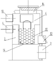
Fig. 1 is the utility model master TV structure schematic diagram.
Fig. 2 is the right TV structure schematic diagram of the utility model.
Fig. 3 is the main TV structure schematic diagram of the utility model Heat Treatment part.
Fig. 4 is the left TV structure schematic diagram of the utility model Heat Treatment part.
Fig. 5 is the utility model Heat Treatment part plan structure schematic diagram.
Among the figure, 1-body of heater, 2-high-temperature flue gas mouth, 3-hotair chamber, the 4-hot air inlet, 5-stereo burning chamber, 6-waste heat reservoir chamber, the 7-Waste gas outlet, 8-heat collecting chamber, 9-boundling fire tube backhaul chamber, 10-re-firing chamber, the positive combustion chamber of 11-, 12-cool air inlet, the 13-smoke inlet, 14-support network, 15-water jacket, the 16-regenerator is put clearly mouth, 17-heat storage, 18-fin.
The specific embodiment
Such as Fig. 1 and 2, body of heater 1 is rectangular structure, and hotair chamber 3 is arranged on body of heater 1 positive centre position, and its outer side-lower is cool air inlet 12, and cold air enters hotair chamber 3 through entrance.There is outlet to be communicated with the hot air inlet 4 of re-firing chamber 10 at hotair chamber 3 inside fronts.Stereo burning chamber 5 is positioned at hotair chamber 3 rears, and it comprises the re-firing chamber 10 on top and the positive combustion chamber 11 of bottom.High-temperature flue gas mouth 2 also is set below stereo burning chamber 5, by high-temperature flue gas mouth 2 positive combustion chamber 11 is communicated with heat collecting chamber 8.Heat collecting chamber 8 is positioned at the position of furnace body inside below, 5 both sides, stereo burning chamber, be boundling fire tube backhaul chamber 9 above it, and heat collecting chamber 8 communicates with boundling fire tube backhaul chamber 9.The skin of body of heater 1 is water jacket 15.
Such as Fig. 3 to 5, hotair chamber 3 places in the waste heat reservoir chamber 6, the top of this waste heat reservoir chamber 6 connects the outlet of boundling fire tube backhaul chamber 9 by smoke inlet 13, the flue gas of discharging in the boundling fire tube backhaul chamber 9 is imported in the waste heat reservoir chamber 6, deposit heat storage 17 in the waste heat reservoir chamber 6 and absorb waste heat in the flue gas.Waste heat reservoir chamber 6 tops arrange regenerator and put clearly mouth 16, are used for placing or cleaning heat storage 17.The upper wall in hotair chamber one side of common sidewall at waste heat reservoir chamber 6 and hotair chamber 3 has fin 18.The bottom of waste heat reservoir chamber 6 is support network 14, connects the Waste gas outlet 7 of body of heater 1 bottom.
During boiler work, cool ambient air is entered in the hotair chamber 3 by cool air inlet 12 and heats, and the air after the heating enters the re-firing chamber 10 of stereo burning chamber 5 by hot air inlet 4.Thermal-flame after the fuel combustion in the re-firing chamber 10 enters positive combustion chamber 11, the high-temperature flue gas of positive combustion chamber drains into heat collecting chamber 8 by high-temperature flue gas mouth 2, and through heat collecting chamber 8, water in 9 pairs of water jackets 15 of boundling fire tube backhaul chamber heats, flue gas after boundling fire tube backhaul chamber 9 discharges enters the waste heat reservoir chamber 6 by smoke inlet 13, the room temperature of waste heat reservoir chamber 6 is raise, and heat energy is sent in the hotair chamber 3 that is adjacent by the share common sidewalls fin, the cold air that enters in the stove is heated in that air heat is indoor, the part of waste heat that heat storage 17 is absorbed in the flue gas also stores, these heat storages can make waste heat reservoir chamber 6 temperature keep stable, and finally making has stable thermal source in the hotair chamber 3.The flue gas that enters in the waste heat reservoir chamber 6 is discharged by the support network 14 of bottom, is discharged outside the body of heater 1 by Waste gas outlet again.
Claims (5)
1. air intake pre-heating energy-saving boiler, comprise body of heater (1), stereo burning chamber (5) is arranged in the body of heater (1), heat collecting chamber (8), boundling fire tube backhaul chamber (9) and water jacket (15), outside air enters stereo burning chamber (5) by cool air inlet (12), high-temperature flue gas in the described stereo burning chamber (5) is discharged by Waste gas outlet (7) after entering heat collecting chamber (8) by high-temperature flue gas mouth (2) and being positioned at the boundling fire tube backhaul chamber (9) of heat collecting chamber (8) top, it is characterized in that: between described boundling fire tube backhaul chamber (9) and the Waste gas outlet (7) waste heat reservoir chamber (6) is set, between described cool air inlet (12) and stereo burning chamber (5) hotair chamber (3) is set, described waste heat reservoir chamber (6) is adjacent with hotair chamber (3) and carry out heat exchange.
2. air intake pre-heating energy-saving boiler according to claim 1, it is characterized in that: described waste heat reservoir chamber (6) sidewall top arranges smoke inlet (13), the bottom is communicated with Waste gas outlet (7), the flue gas that boundling fire tube backhaul chamber (9) discharges enters waste heat reservoir chamber (6) by the smoke inlet (13) of sidewall top, is discharged by the Waste gas outlet (7) of bottom again.
3. air intake pre-heating energy-saving boiler according to claim 1 and 2 is characterized in that: heat storage (17) is housed in the described waste heat reservoir chamber (6), and described heat storage (17) is placed on the support network (14) that the interior level of reservoir chamber (6) installs.
4. air intake pre-heating energy-saving boiler according to claim 1 and 2 is characterized in that: described waste heat reservoir chamber (6) is equipped with fin (18) with hotair chamber one side of the adjacent wall of hotair chamber (3).
5. air intake pre-heating energy-saving boiler according to claim 3 is characterized in that: described waste heat reservoir chamber (6) top arranges regenerator and puts clearly mouthful (16).
Priority Applications (1)
| Application Number | Priority Date | Filing Date | Title |
|---|---|---|---|
| CN2013202230494U CN203249261U (en) | 2013-04-27 | 2013-04-27 | Intake air preheating energy-saving boiler |
Applications Claiming Priority (1)
| Application Number | Priority Date | Filing Date | Title |
|---|---|---|---|
| CN2013202230494U CN203249261U (en) | 2013-04-27 | 2013-04-27 | Intake air preheating energy-saving boiler |
Publications (1)
| Publication Number | Publication Date |
|---|---|
| CN203249261U true CN203249261U (en) | 2013-10-23 |
Family
ID=49375700
Family Applications (1)
| Application Number | Title | Priority Date | Filing Date |
|---|---|---|---|
| CN2013202230494U Expired - Fee Related CN203249261U (en) | 2013-04-27 | 2013-04-27 | Intake air preheating energy-saving boiler |
Country Status (1)
| Country | Link |
|---|---|
| CN (1) | CN203249261U (en) |
Cited By (1)
| Publication number | Priority date | Publication date | Assignee | Title |
|---|---|---|---|---|
| CN103697450A (en) * | 2013-11-29 | 2014-04-02 | 山西新聚星锅炉有限公司 | Thermal-storing chamber boiler |
-
2013
- 2013-04-27 CN CN2013202230494U patent/CN203249261U/en not_active Expired - Fee Related
Cited By (1)
| Publication number | Priority date | Publication date | Assignee | Title |
|---|---|---|---|---|
| CN103697450A (en) * | 2013-11-29 | 2014-04-02 | 山西新聚星锅炉有限公司 | Thermal-storing chamber boiler |
Similar Documents
| Publication | Publication Date | Title |
|---|---|---|
| CN203908010U (en) | Vertical type hot air and hot water boiler | |
| CN203116158U (en) | Novel energy-saving and environment-friendly kang | |
| CN203249261U (en) | Intake air preheating energy-saving boiler | |
| CN204006649U (en) | A kind of multitube high temperature hot-blast furnace | |
| CN103697501A (en) | Grate heat exchange type biomass cooking and heating stove | |
| CN203323361U (en) | Energy-saving high-temperature hot-blast heater | |
| CN209310262U (en) | A kind of heating heat recovery boiler | |
| CN103017207B (en) | Heat-insulating energy-saving heating stove | |
| CN207394909U (en) | A kind of energy-saving heater | |
| CN201811424U (en) | Inverse combustion heating hot-blast furnace | |
| CN204555312U (en) | Living beings both sides shape coil pipe heat-conducting oil furnace | |
| CN104061678B (en) | Heart-shaped heat exchanger tube multitube high temperature hot-blast furnace | |
| CN202733990U (en) | Double-water jacket full-flue heat exchange cooking range | |
| CN211177409U (en) | Integrated smoke-collecting gas heating water heater | |
| CN203024410U (en) | Energy-saving boiler | |
| CN209622916U (en) | A kind of new energy source energy-saving steam heating furnace | |
| CN203419945U (en) | Hot-blast stove provided with high-temperature flues and low-temperature flues | |
| CN107255292A (en) | A kind of energy-saving heater | |
| CN209431658U (en) | A kind of sun glasshouse's heating boiler | |
| CN201526991U (en) | Water heating energy-saving boiler for cooking | |
| CN105526602A (en) | Energy-saving heating stove | |
| CN204176694U (en) | A kind of energy-saving heater | |
| CN202303856U (en) | Warming boiler for brick bed | |
| CN202328783U (en) | Energy-saving environment-friendly module furnace | |
| CN2781271Y (en) | Adjustable composite heating frunace |
Legal Events
| Date | Code | Title | Description |
|---|---|---|---|
| C14 | Grant of patent or utility model | ||
| GR01 | Patent grant | ||
| C17 | Cessation of patent right | ||
| CF01 | Termination of patent right due to non-payment of annual fee |
Granted publication date: 20131023 Termination date: 20140427 |