CN203236179U - Rotating pipe-cutting chuck - Google Patents
Rotating pipe-cutting chuck Download PDFInfo
- Publication number
- CN203236179U CN203236179U CN 201320123902 CN201320123902U CN203236179U CN 203236179 U CN203236179 U CN 203236179U CN 201320123902 CN201320123902 CN 201320123902 CN 201320123902 U CN201320123902 U CN 201320123902U CN 203236179 U CN203236179 U CN 203236179U
- Authority
- CN
- China
- Prior art keywords
- chuck
- output shaft
- reduction box
- bearing block
- cutting
- Prior art date
- Legal status (The legal status is an assumption and is not a legal conclusion. Google has not performed a legal analysis and makes no representation as to the accuracy of the status listed.)
- Expired - Fee Related
Links
- 230000005540 biological transmission Effects 0.000 claims abstract description 6
- 230000003028 elevating effect Effects 0.000 claims description 21
- 238000003698 laser cutting Methods 0.000 abstract description 10
- 238000009434 installation Methods 0.000 abstract 3
- 230000001105 regulatory effect Effects 0.000 abstract 1
- 244000248349 Citrus limon Species 0.000 description 2
- 235000005979 Citrus limon Nutrition 0.000 description 2
Images

Landscapes
- Laser Beam Processing (AREA)
- Arc Welding In General (AREA)
Abstract
The utility model provides a rotating pipe-cutting chuck which comprises a fixing installation plate, a moving sliding plate, a bearing block, a nut base, a chuck lifting lead screw, a reduction gearbox, a reduction gearbox output shaft, a chuck body and a servo motor, wherein a dovetail groove and the bearing block are formed in the fixing installation plate, the chuck lifting lead screw is connected with the bearing block through a bearing, one side face of the moving sliding plate is in transmission connection with the chuck lifting lead screw of the fixing installation plate through the nut base fixed with the side face of the moving sliding plate, the other side face of the moving sliding plate is fixedly connected with the reduction gearbox driven by the servo motor, and the output shaft of the reduction gearbox is fixedly connected with the chuck body. The rotating pipe-cutting chuck resolves the problem that the position between a cutting head and the wall of a pipe needs to be regulated continuously in pipe cutting by means of plasma and laser cutting machines, and therefore the rotating pipe-cutting chuck enables the application range of the plasma and laser cutting machines to be wider.
Description
Technical field
The utility model relates to the work piece holder that cutting machine is used, particularly a kind of rotation pipe cutting chuck.
Background technology
In the industrial circle, chuck is a lot of for the processing usefulness of rotational workpieces, in using plasma, laser cutting machine, when incising pipes, not only require the tubing rotation, also require because the difference of pipe diameter, when using cutting machine, position between the tube wall of cutting head and tubing will constantly be adjusted, and these have proposed a difficult problem all for plasma, laser cutting machine incising pipes, so that plasma, laser cutting machine can not be widely used in the cutting of tubing always.
Summary of the invention
The purpose of this utility model is to provide a kind of convenient rotation pipe cutting chuck that uses plasma, laser cutting machine incising pipes.
In order to achieve the above object, the technical solution of the utility model is: a kind of rotation pipe cutting chuck, comprise mounting plate, moving slide board, bearing block, nut seat, the chuck elevating screw, reduction box, reduction gearbox output shaft, chuck and servomotor, mounting plate is provided with dovetail groove and bearing block, the chuck elevating screw is by bearing and bearing block load, a side of moving slide board is by being in transmission connection with its fixing nut seat and the chuck elevating screw of mounting plate, another side of described moving slide board is fixedly connected with the reduction box by driven by servomotor, and the output shaft of reduction box is fixedly connected with chuck.
The output shaft of described reduction box stretches out the part and chuck load of reduction box, the other end of output shaft is by the large synchronizing wheel load of expansion sleeve and reduction box, the inner of described output shaft is provided with the locking nut that is threaded, and the inner face of locking nut and the end face of expansion sleeve offset.
Gag also is equipped with at the dovetail groove place that described moving slide board and mounting plate are slidingly connected.
The upper end of described chuck elevating screw is provided with square or hexagonal adjusting rod.
After adopting said structure, owing to comprise mounting plate, moving slide board, bearing block, nut seat, chuck elevating screw, reduction box, reduction gearbox output shaft, chuck and servomotor, mounting plate is provided with dovetail groove and bearing block, the chuck elevating screw is by bearing and bearing block load, a side of moving slide board is by being in transmission connection with its fixing nut seat and the chuck elevating screw of mounting plate, another side of described moving slide board is fixedly connected with the reduction box by driven by servomotor, and the output shaft of reduction box is fixedly connected with chuck.Therefore after chuck blocks pipe fitting, workpiece can rotate with chuck under driven by servomotor, because the stroke of cutting head is limited, large for diameter, little different pipe fitting need to be adjusted the position between the tube wall of cutting head and tubing, as long as utilize the adjusting rod on the moving chuck elevating screw of instrument lemon, moving slide board will drive chuck and reach needed position in the mounting plate movement, satisfy the requirement of cutting, solved plasma, laser cutting machine is in the cutting of tubing, the difficult problem that position between the tube wall of cutting head and tubing will constantly be adjusted makes plasma, laser cutting machine is more widely used.
Description of drawings
Fig. 1 is structural representation of the present utility model;
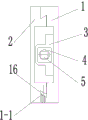
Fig. 2 is mounting plate and moving slide board top view partly among Fig. 1.
The specific embodiment
The embodiment that provides below in conjunction with accompanying drawing is described in further detail the utility model.
Referring to Fig. 1, shown in 2, a kind of rotation pipe cutting chuck, comprise mounting plate 1, moving slide board 2, bearing block 3, nut seat 4, chuck elevating screw 5, reduction box 6, reduction gearbox output shaft 7, chuck 8 and servomotor 9, mounting plate 1 is provided with dovetail groove 1-1 and bearing block 3, chuck elevating screw 5 is by bearing and bearing block 3 loads, a side of moving slide board 2 is by being in transmission connection with the chuck elevating screw 5 of its fixing nut seat 4 with mounting plate 1, another side of described moving slide board 2 is fixedly connected with the reduction box 6 that is driven by servomotor 9, and the output shaft 7 of reduction box 6 is fixedly connected with chuck 8.
For the chuck stability of rotation, the output shaft 7 of described reduction box 6 stretches out the part and chuck 8 loads of reduction box 6, the other end of output shaft 7 is by large synchronizing wheel 11 loads of expansion sleeve 12 with reduction box 6, the inner of described output shaft 7 is provided with the locking nut 13 that is threaded, and the end face of the inner face of locking nut 13 and expansion sleeve 12 offsets.
For chuck is moved up and down steadily with moving slide board 2, described moving slide board 2 also is equipped with gag 16 with the dovetail groove 1-1 place that mounting plate 1 is slidingly connected.
For the rotation of handled easily chuck elevating screw 5, the upper end of described chuck elevating screw 5 is provided with square or hexagonal adjusting rod.
The utility model in use, comprise mounting plate 1, moving slide board 2, bearing block 3, nut seat 4, chuck elevating screw 5, reduction box 6, reduction gearbox output shaft 7, chuck 8 and servomotor 9, mounting plate 1 is provided with dovetail groove 1-1 and bearing block 3, chuck elevating screw 5 is by bearing and bearing block 3 loads, a side of moving slide board 2 is by being in transmission connection with the chuck elevating screw 5 of its fixing nut seat 4 with mounting plate 1, another side of described moving slide board 2 is fixedly connected with the reduction box 6 that is driven by servomotor 9, the output shaft 7 of reduction box 6 is fixedly connected with chuck 8, therefore after chuck 8 blocks pipe fitting, pipe fitting can rotate with chuck 8 under servomotor 9 drives, when the position between the tube wall of needs adjustment cutting head and tubing, as long as utilize the adjusting rod on the moving chuck elevating screw 5 of instrument lemon, moving slide board 2 will drive chuck 8 and reach needed position in mounting plate 1 movement, satisfy the requirement of cutting, solved plasma, laser cutting machine is in the cutting of tubing, position between the tube wall of cutting head and tubing to constantly adjust a difficult problem, make plasma, laser cutting machine is more widely used.
Claims (4)
1. one kind is rotated the pipe cutting chuck, it is characterized in that: comprise mounting plate (1), moving slide board (2), bearing block (3), nut seat (4), chuck elevating screw (5), reduction box (6), reduction gearbox output shaft (7), chuck (8) and servomotor (9), mounting plate (1) is provided with dovetail groove (1-1) and bearing block (3), chuck elevating screw (5) is by bearing and bearing block (3) load, a side of moving slide board (2) is by being in transmission connection with the chuck elevating screw (5) of its fixing nut seat (4) with mounting plate (1), another side of described moving slide board (2) is fixedly connected with the reduction box (6) that is driven by servomotor (9), and the output shaft (7) of reduction box (6) is fixedly connected with chuck (8).
2. rotation pipe cutting chuck according to claim 1, it is characterized in that: the output shaft (7) of described reduction box (6) stretches out the part and chuck (8) load of reduction box (6), the other end of output shaft (7) is by large synchronizing wheel (11) load of expansion sleeve (12) with reduction box (6), the inner of described output shaft (7) is provided with the locking nut (13) that is threaded, and the end face of the inner face of locking nut (13) and expansion sleeve (12) offsets.
3. rotation pipe cutting chuck according to claim 1 is characterized in that: described moving slide board (2) locates also to be equipped with gag (16) with the dovetail groove (1-1) that mounting plate (1) is slidingly connected.
4. rotation pipe cutting chuck according to claim 1, it is characterized in that: the upper end of described chuck elevating screw (5) is provided with square or hexagonal adjusting rod.
Priority Applications (1)
| Application Number | Priority Date | Filing Date | Title |
|---|---|---|---|
| CN 201320123902 CN203236179U (en) | 2013-03-19 | 2013-03-19 | Rotating pipe-cutting chuck |
Applications Claiming Priority (1)
| Application Number | Priority Date | Filing Date | Title |
|---|---|---|---|
| CN 201320123902 CN203236179U (en) | 2013-03-19 | 2013-03-19 | Rotating pipe-cutting chuck |
Publications (1)
| Publication Number | Publication Date |
|---|---|
| CN203236179U true CN203236179U (en) | 2013-10-16 |
Family
ID=49313511
Family Applications (1)
| Application Number | Title | Priority Date | Filing Date |
|---|---|---|---|
| CN 201320123902 Expired - Fee Related CN203236179U (en) | 2013-03-19 | 2013-03-19 | Rotating pipe-cutting chuck |
Country Status (1)
| Country | Link |
|---|---|
| CN (1) | CN203236179U (en) |
Cited By (3)
| Publication number | Priority date | Publication date | Assignee | Title |
|---|---|---|---|---|
| CN103659142A (en) * | 2013-11-28 | 2014-03-26 | 苏州凯尔博精密机械有限公司 | Clamping mechanism of water filter bucket cutting and welding machine |
| CN105921891A (en) * | 2016-06-07 | 2016-09-07 | 济南大学 | Tube supporting clamps |
| CN106002067A (en) * | 2016-06-13 | 2016-10-12 | 济南大学 | Auxiliary supporting fixture for circular tube cutting |
-
2013
- 2013-03-19 CN CN 201320123902 patent/CN203236179U/en not_active Expired - Fee Related
Cited By (4)
| Publication number | Priority date | Publication date | Assignee | Title |
|---|---|---|---|---|
| CN103659142A (en) * | 2013-11-28 | 2014-03-26 | 苏州凯尔博精密机械有限公司 | Clamping mechanism of water filter bucket cutting and welding machine |
| CN103659142B (en) * | 2013-11-28 | 2016-01-27 | 苏州凯尔博精密机械有限公司 | A kind of water-purifying tank cutting bonding machine clamp system |
| CN105921891A (en) * | 2016-06-07 | 2016-09-07 | 济南大学 | Tube supporting clamps |
| CN106002067A (en) * | 2016-06-13 | 2016-10-12 | 济南大学 | Auxiliary supporting fixture for circular tube cutting |
Similar Documents
| Publication | Publication Date | Title |
|---|---|---|
| CN203599874U (en) | Clamping tool for milling key grooves of shaft parts | |
| CN103949897B (en) | Double-work position hydraulic clamping rotating table | |
| CN204818206U (en) | Improved generation is milling machine for sleeping in immediately | |
| CN204235165U (en) | A kind of pipe fitting self-alignment cramping arrangement | |
| CN204321682U (en) | The two-sided tapping fixture of Multiaxial tapping machine | |
| CN103240460B (en) | A kind of processing unit (plant) of large-scale workpiece tapered hole internal keyway | |
| CN204975989U (en) | Annular work piece bores attacks device | |
| CN103551881A (en) | Mechanical automatic rotation clamp | |
| CN204053638U (en) | A kind of multiplex graduation drilling milling apparatus | |
| CN205096975U (en) | Surperficial polishing device of automation of flange | |
| CN204913370U (en) | Quick locking flat -nose pliers of adjustable pitch -row | |
| CN104162712A (en) | Cutting device and method of tubular products | |
| CN202147134U (en) | Universal drilling and tapping dual-purpose tool | |
| CN210498401U (en) | Adjustable tool rest of numerical control lathe | |
| CN205218919U (en) | Frock clamp's manual micromatic setting | |
| CN204747542U (en) | But height -adjusting's lathe sword support | |
| CN202684537U (en) | Automatic positioning frame | |
| CN219113392U (en) | A servo traverse drilling and tapping machine | |
| CN101468410A (en) | Split type gear chamfering machine and method for processing the same | |
| CN203944883U (en) | Large-scale three dimensional drilling machine three-dimensional adjustment platform mechanism | |
| CN203610713U (en) | Simple radial drilling machine with high efficiency | |
| CN103978253B (en) | Large-scale three dimensional drilling machine three-dimensional adjustment platform mechanism | |
| CN203542119U (en) | Mechanical automatic rotary fixture | |
| CN202639376U (en) | Automatic positioning frame | |
| CN102922359A (en) | Feeding structure of numerical control cutter rest of vertical lathe |
Legal Events
| Date | Code | Title | Description |
|---|---|---|---|
| C14 | Grant of patent or utility model | ||
| GR01 | Patent grant | ||
| C17 | Cessation of patent right | ||
| CF01 | Termination of patent right due to non-payment of annual fee |
Granted publication date: 20131016 Termination date: 20140319 |