CN203227142U - Connecting structure of syringe piston and cylindrical core rod - Google Patents
Connecting structure of syringe piston and cylindrical core rod Download PDFInfo
- Publication number
- CN203227142U CN203227142U CN 201320195486 CN201320195486U CN203227142U CN 203227142 U CN203227142 U CN 203227142U CN 201320195486 CN201320195486 CN 201320195486 CN 201320195486 U CN201320195486 U CN 201320195486U CN 203227142 U CN203227142 U CN 203227142U
- Authority
- CN
- China
- Prior art keywords
- core rod
- mandrel
- processed
- cylindrical core
- cylindrical
- Prior art date
- Legal status (The legal status is an assumption and is not a legal conclusion. Google has not performed a legal analysis and makes no representation as to the accuracy of the status listed.)
- Expired - Fee Related
Links
- 239000002994 raw material Substances 0.000 abstract description 3
- 239000004743 Polypropylene Substances 0.000 description 13
- 239000000463 material Substances 0.000 description 7
- -1 polypropylene Polymers 0.000 description 7
- 229920001155 polypropylene Polymers 0.000 description 7
- 239000003814 drug Substances 0.000 description 2
- 238000000034 method Methods 0.000 description 2
- 239000000243 solution Substances 0.000 description 2
- 239000002699 waste material Substances 0.000 description 2
- 238000002347 injection Methods 0.000 description 1
- 239000007924 injection Substances 0.000 description 1
- 239000007788 liquid Substances 0.000 description 1
- 238000000465 moulding Methods 0.000 description 1
Images


Landscapes
- Infusion, Injection, And Reservoir Apparatuses (AREA)
Abstract
本实用新型属于医疗器具领域,具体是涉及一种注射器活塞与筒型芯杆的连接结构,一种注射器活塞与筒型芯杆的连接结构,其特征是:在筒型芯杆的前端加工有固定芯杆头,在固定芯杆头的上面安装有活塞,在筒型芯杆的末端加工有芯杆推柄,在芯杆推柄的上面安装有按钮,在筒型芯杆的中部位置加工有四片导向片,综上所述,本实用新型由于在筒型芯杆( 4 )的上面加工有导向片( 5 ),这样可以把筒型芯杆( 4 )的横截面加工成很小,这样可以大大节省原材料,由于有导向片( 5 )的作用,可以保证筒型芯杆( 4 )在针筒( 1 )内的工作稳定可靠。
The utility model belongs to the field of medical appliances, in particular to a connection structure between a syringe piston and a cylindrical core rod, a connection structure between a syringe piston and a cylindrical core rod, and is characterized in that: the front end of the cylindrical core rod is processed with Fixed mandrel head, a piston is installed on the top of the fixed mandrel head, a mandrel push handle is processed at the end of the cylindrical mandrel, a button is installed on the mandrel push handle, and the middle position of the mandrel mandrel is processed There are four pieces of guide pieces. To sum up, the utility model has guide pieces ( 5 ) processed on the cylindrical mandrel ( 4 ), so that the cross section of the cylindrical mandrel ( 4 ) can be processed into a very small , which can greatly save raw materials, and because of the role of the guide plate ( 5 ), it can ensure that the cylindrical core rod ( 4 ) works stably and reliably in the needle cylinder ( 1 ).
Description
技术领域 technical field
本实用新型属于医疗器具领域,具体是涉及一种注射器活塞与筒型芯杆的连接结构。The utility model belongs to the field of medical appliances, in particular to a connection structure between a syringe piston and a cylindrical core rod.
背景技术 Background technique
目前临床上使用的注射器的芯杆,普遍存在着浪费原材料的结构设计,因为临床上使用的注射器是一次性的,所以浪费相当的惊人,医护人员在吸药和注射操作时,注射器芯杆推拉也比较费力,而且手易从外套边缘滑落,从而导致医疗事故的发生。At present, the core rods of clinically used syringes generally have a structural design that wastes raw materials. Because clinically used syringes are disposable, the waste is quite amazing. When medical staff suck medicine and inject, the syringe core rods are pushed and pulled. It is also more laborious, and the hands are easy to slip off from the edge of the coat, resulting in medical accidents.
实用新型内容 Utility model content
本实用新型的目的,就在于克服上述的缺点,而提供的一种注射器活塞与筒型芯杆的连接结构。The purpose of this utility model is to overcome the above-mentioned shortcomings, and provide a connection structure between a syringe piston and a barrel core rod.
本实用新型是这样实现的:一种注射器活塞与筒型芯杆的连接结构,其特征是:在筒型芯杆的前端加工有固定芯杆头,在固定芯杆头的上面安装有活塞,在筒型芯杆的末端加工有芯杆推柄,在芯杆推柄的上面安装有按钮,在筒型芯杆的中部位置加工有四片导向片。The utility model is realized in the following way: a connection structure between a syringe piston and a cylindrical core rod, which is characterized in that: a fixed core rod head is processed on the front end of the cylindrical core rod, and a piston is installed on the fixed core rod head. A core rod push handle is processed at the end of the cylindrical core rod, a button is installed on the top of the core rod push handle, and four guide pieces are processed at the middle of the cylindrical core rod.
附图说明 Description of drawings
下面结合附图对本实用新型做进一步详细的说明。Below in conjunction with accompanying drawing, the utility model is described in further detail.
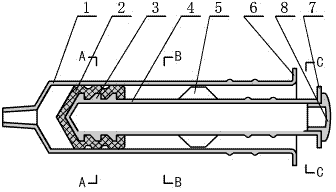
图1是本实用新型的主剖视图。Fig. 1 is a main sectional view of the utility model.
图2是图1的“A-A”剖视图。FIG. 2 is a cross-sectional view of “A-A” in FIG. 1 .
图3是图1的“B-B”剖视图。Fig. 3 is a cross-sectional view along "B-B" of Fig. 1 .
图4是图1的“C-C”剖视图。Fig. 4 is a "C-C" sectional view of Fig. 1 .
图中各标号说明如下:The labels in the figure are explained as follows:
1、针筒,2、活塞,3、固定芯杆头,4、筒型芯杆,5、导向片,6、针筒翻边,7、芯杆推柄,8、按钮。1. Syringe, 2. Piston, 3. Fixed mandrel head, 4. Cylindrical mandrel, 5. Guide piece, 6. Syringe flanging, 7. Mandrel push handle, 8. Button.
具体实施方式 Detailed ways
本实用新型的针筒1选用PP聚丙烯材料在模具中一次加工成型,针筒1的作用是储存药液并使活塞2在针筒1内滑行,活塞2选用丁基橡胶材料在模具中一次加工成型,活塞2的作用就是通过芯杆推柄7的推力,把针筒1内储存的药液通过针头,向患者体内注射,或者把针筒1内储存的药液通过针头进行其它的操作等,固定芯杆头3选用PP聚丙烯材料在模具中一次加工成型,其作用就是固定活塞2,筒型芯杆4选用PP聚丙烯材料在模具中一次加工成型,其作用就是保证固定芯杆头3上面的活塞2工作稳定可靠,导向片5选用PP聚丙烯材料在模具中一次加工成型,其作用就是保证筒型芯杆4在针筒1内工作稳定可靠,针筒翻边6选用PP聚丙烯材料在模具中一次加工成型,其作用就是注射时操作方便稳定可靠,芯杆推柄7选用PP聚丙烯材料在模具中一次加工成型,其作用就是工作时,保证筒型芯杆4工作稳定可靠,按钮8选用PP聚丙烯材料在模具中一次加工成型,其作用就是操作方便可靠。The
综上所述,本实用新型由于在筒型芯杆4的上面加工有导向片5,这样可以把筒型芯杆4的横截面加工成很小,这样可以大大节省原材料,由于有导向片5的作用,可以保证筒型芯杆4在针筒1内的工作稳定可靠。In summary, the utility model can process the cross-section of the
Claims (1)
Priority Applications (1)
| Application Number | Priority Date | Filing Date | Title |
|---|---|---|---|
| CN 201320195486 CN203227142U (en) | 2013-04-18 | 2013-04-18 | Connecting structure of syringe piston and cylindrical core rod |
Applications Claiming Priority (1)
| Application Number | Priority Date | Filing Date | Title |
|---|---|---|---|
| CN 201320195486 CN203227142U (en) | 2013-04-18 | 2013-04-18 | Connecting structure of syringe piston and cylindrical core rod |
Publications (1)
| Publication Number | Publication Date |
|---|---|
| CN203227142U true CN203227142U (en) | 2013-10-09 |
Family
ID=49283293
Family Applications (1)
| Application Number | Title | Priority Date | Filing Date |
|---|---|---|---|
| CN 201320195486 Expired - Fee Related CN203227142U (en) | 2013-04-18 | 2013-04-18 | Connecting structure of syringe piston and cylindrical core rod |
Country Status (1)
| Country | Link |
|---|---|
| CN (1) | CN203227142U (en) |
-
2013
- 2013-04-18 CN CN 201320195486 patent/CN203227142U/en not_active Expired - Fee Related
Similar Documents
| Publication | Publication Date | Title |
|---|---|---|
| CN203227145U (en) | Injection syringe cylindrical core pin with four guide sheets | |
| CN203227146U (en) | Injection syringe core pin with three guide sheets | |
| CN203227141U (en) | Injection syringe cylindrical core pin with three guide sheets and antislip rings | |
| CN203227152U (en) | Injection syringe core pin with three ultra-short guide sheets | |
| CN203227147U (en) | Injection syringe core pin with five guide sheets | |
| CN203227132U (en) | Connecting structure of syringe piston and guide piece core rod | |
| CN203227143U (en) | Connecting structure of syringe piston and three-guide-piece cylindrical core rod | |
| CN203227133U (en) | Connecting structure of syringe piston and core rod | |
| CN203227150U (en) | Linking structure of syringe piston and three-guide-piece core rod | |
| CN203227151U (en) | Syringe core bar with six guide blades | |
| CN203227153U (en) | Syringe with inner stopper | |
| CN104107473A (en) | Syringe piston and cylindrical mandrel connecting structure | |
| CN104107472A (en) | Cylindrical-core-rod syringe with guide sleeve | |
| CN203227148U (en) | Connecting structure of syringe piston and antiskid ring cylindrical core rod | |
| CN104107474A (en) | Syringe piston and guide vane mandrel connecting structure | |
| CN104107476A (en) | Syringe piston and three-guide-vane mandrel connecting structure | |
| CN104107475A (en) | Injection syringe core pin with five guide sheets | |
| CN104107484A (en) | Injector core bar with six guide plates | |
| CN203227149U (en) | Cylindrical core bar for syringes with antislip ring | |
| CN104107479A (en) | Syringe core bar with three ultrashort guide sheets | |
| CN104107485A (en) | Syringe piston and mandrel connecting structure | |
| CN104107488A (en) | Hollow-push-rod syringe with guide sleeve | |
| CN104107477A (en) | Syringe piston and three-guide-vane cylindrical mandrel connecting structure | |
| CN204147367U (en) | A kind of split type syringe with spiral quick fixation structure | |
| CN104107483A (en) | Syringe piston and antislip cylindrical mandrel connecting structure |
Legal Events
| Date | Code | Title | Description |
|---|---|---|---|
| C14 | Grant of patent or utility model | ||
| GR01 | Patent grant | ||
| CF01 | Termination of patent right due to non-payment of annual fee | ||
| CF01 | Termination of patent right due to non-payment of annual fee |
Granted publication date: 20131009 Termination date: 20190418 |