CN203223721U - Bracket for set top box for television - Google Patents
Bracket for set top box for television Download PDFInfo
- Publication number
- CN203223721U CN203223721U CN 201320158893 CN201320158893U CN203223721U CN 203223721 U CN203223721 U CN 203223721U CN 201320158893 CN201320158893 CN 201320158893 CN 201320158893 U CN201320158893 U CN 201320158893U CN 203223721 U CN203223721 U CN 203223721U
- Authority
- CN
- China
- Prior art keywords
- top box
- utility
- base plate
- bracket
- model
- Prior art date
- Legal status (The legal status is an assumption and is not a legal conclusion. Google has not performed a legal analysis and makes no representation as to the accuracy of the status listed.)
- Expired - Fee Related
Links
Images

Landscapes
- Casings For Electric Apparatus (AREA)
Abstract
本实用新型公开了一种电视机机顶盒的托座,包括底板和沉孔,所述底板上安装有圆孔,且在所述底板的左右两侧安装有加强筋,所述底板的一端安装有挡板,所述底板的另外一端与所述沉孔所在的板相连接。本实用新型能用于保护机顶盒不会掉落;另外,当不看电视时遥控器也可以放置在机顶盒托座上面;还有可以防止机顶盒滑落。
The utility model discloses a bracket for a TV set-top box, which comprises a base plate and a counterbore. The base plate is provided with round holes, and reinforcing ribs are installed on the left and right sides of the base plate. One end of the base plate is installed with The other end of the bottom plate is connected to the plate where the counterbore is located. The utility model can be used to protect the set-top box from falling; in addition, the remote controller can also be placed on the bracket of the set-top box when not watching TV; and the utility model can also prevent the set-top box from slipping.
Description
技术领域 technical field
本实用新型涉及一种电视机机顶盒的托座。 The utility model relates to a bracket for a TV set-top box. the
背景技术 Background technique
随着现代社会的快速发展,液晶电视越来越受到大众的喜欢。目前大多数液晶电视都是安装在墙壁上的,可是电视机机顶盒没有地方安装一般就是放在凳子上或者放在电视机上,这样极其不便容易掉落,造成摔坏或者砸到人。这种电视机机顶盒托座可以很好的解决这个问题。 With the rapid development of modern society, LCD TVs are becoming more and more popular among the public. At present, most LCD TVs are installed on the wall, but there is no place to install the TV set-top box, and they are usually placed on a stool or on the TV, which is extremely inconvenient and easy to fall, causing damage or hitting people. This TV set-top box bracket can well solve this problem. the
发明内容 Contents of the invention
本实用新型的目的在于克服现有技术存在的以上问题,提供一种电视机机顶盒的托座,从而更方便高效,安全可靠。 The purpose of the utility model is to overcome the above problems in the prior art and provide a bracket for a TV set-top box, which is more convenient, efficient, safe and reliable. the
为实现上述技术目的,达到上述技术效果,本实用新型通过以下技术方案实现: In order to achieve the above-mentioned technical purpose and achieve the above-mentioned technical effect, the utility model is realized through the following technical solutions:
一种电视机机顶盒的托座,包括底板和沉孔,所述底板上安装有圆孔,且在所述底板的左右两侧安装有加强筋,所述底板的一端安装有挡板,所述底板的另外一端与所述沉孔所在的板相连接。 A bracket for a TV set-top box, comprising a base plate and a counterbore, a round hole is installed on the base plate, reinforcing ribs are installed on the left and right sides of the base plate, a baffle plate is installed on one end of the base plate, the The other end of the bottom plate is connected with the plate where the counterbore is located.
本实用新型的有益效果是: The beneficial effects of the utility model are:
本实用新型能用于保护机顶盒不会掉落;另外,当不看电视时遥控器也可以放置在机顶盒托座上面;还有可以防止机顶盒滑落。 The utility model can be used to protect the set-top box from falling; in addition, the remote controller can also be placed on the bracket of the set-top box when not watching TV; and the utility model can also prevent the set-top box from slipping.
附图说明 Description of drawings
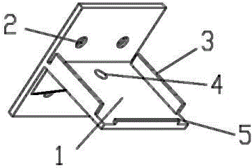
图1为本实用新型的立体结构示意图; Fig. 1 is the three-dimensional structure schematic diagram of the present utility model;
图2为本实用新型的主视图; Fig. 2 is the front view of the utility model;
图3为本实用新型的俯视图。 Fig. 3 is a top view of the utility model.
图中标号说明:1、底板,2、沉孔,3、加强筋,4、圆孔,5、挡板。 Explanation of symbols in the figure: 1, bottom plate, 2, counterbore, 3, reinforcing rib, 4, circular hole, 5, baffle plate. the
具体实施方式 Detailed ways
下面将参考附图并结合实施例,来详细说明本实用新型。 The utility model will be described in detail below with reference to the accompanying drawings and in conjunction with the embodiments. the
参照图1所示,一种电视机机顶盒的托座,包括底板1和沉孔2,所述底板1上安装有圆孔4,且在所述底板1的左右两侧安装有加强筋3,所述底板1的一端安装有挡板5,所述底板1的另外一端与所述沉孔2所在的板相连接。 With reference to shown in Figure 1, a kind of bracket of TV set-top box comprises base plate 1 and counterbore 2, and circular hole 4 is installed on described base plate 1, and reinforcing rib 3 is installed on the left and right sides of described base plate 1, A baffle 5 is installed at one end of the bottom plate 1 , and the other end of the bottom plate 1 is connected to the plate where the counterbore 2 is located. the
本实用新型的原理: The principle of the utility model:
本实用新型是通过木板联接设计成一个“T”形的机顶盒托座;沉孔2所在的底板上的那块小长方体上面开了4个沉孔,这4个沉孔里面都用于安装螺钉,把机顶盒托座安装在墙壁上;底板1和沉孔2所在的板的连接处还设计了两个三角形的加强筋;底板1上面开了一个圆孔4,用于通过机顶盒的电源线。 The utility model is designed as a "T"-shaped set-top box bracket through the connection of wooden boards; 4 countersunk holes are opened on the small cuboid on the bottom plate where the counterbore 2 is located, and these 4 counterbore holes are used for installing screws. , the set-top box bracket is installed on the wall; two triangular reinforcing ribs are also designed at the junction of the plate where the bottom plate 1 and the counterbore 2 are located; a round hole 4 is opened above the bottom plate 1 for the power cord of the set-top box.
以上所述仅为本实用新型的优选实施例而已,并不用于限制本实用新型,对于本领域的技术人员来说,本实用新型可以有各种更改和变化。凡在本实用新型的精神和原则之内,所作的任何修改、等同替换、改进等,均应包含在本发明的保护范围之内。 The above descriptions are only preferred embodiments of the utility model, and are not intended to limit the utility model. For those skilled in the art, the utility model can have various modifications and changes. Any modifications, equivalent replacements, improvements, etc. made within the spirit and principles of the present utility model shall be included within the protection scope of the present invention. the
Claims (1)
Priority Applications (1)
| Application Number | Priority Date | Filing Date | Title |
|---|---|---|---|
| CN 201320158893 CN203223721U (en) | 2013-04-02 | 2013-04-02 | Bracket for set top box for television |
Applications Claiming Priority (1)
| Application Number | Priority Date | Filing Date | Title |
|---|---|---|---|
| CN 201320158893 CN203223721U (en) | 2013-04-02 | 2013-04-02 | Bracket for set top box for television |
Publications (1)
| Publication Number | Publication Date |
|---|---|
| CN203223721U true CN203223721U (en) | 2013-10-02 |
Family
ID=49250725
Family Applications (1)
| Application Number | Title | Priority Date | Filing Date |
|---|---|---|---|
| CN 201320158893 Expired - Fee Related CN203223721U (en) | 2013-04-02 | 2013-04-02 | Bracket for set top box for television |
Country Status (1)
| Country | Link |
|---|---|
| CN (1) | CN203223721U (en) |
Cited By (1)
| Publication number | Priority date | Publication date | Assignee | Title |
|---|---|---|---|---|
| CN104019178A (en) * | 2014-05-20 | 2014-09-03 | 李理 | Electric controller mounting base |
-
2013
- 2013-04-02 CN CN 201320158893 patent/CN203223721U/en not_active Expired - Fee Related
Cited By (1)
| Publication number | Priority date | Publication date | Assignee | Title |
|---|---|---|---|---|
| CN104019178A (en) * | 2014-05-20 | 2014-09-03 | 李理 | Electric controller mounting base |
Similar Documents
| Publication | Publication Date | Title |
|---|---|---|
| CN208507463U (en) | A kind of capacitor installation part of Fast Installation | |
| CN202493876U (en) | Bracket for general television set top box | |
| CN202977881U (en) | Crystal head installation new structure | |
| CN206864737U (en) | A kind of wall safety socket structure of power supply | |
| CN204741646U (en) | A new tool-free rack structure | |
| CN204333321U (en) | Ground terminal fixing assembly and refrigerator | |
| CN201919272U (en) | Sub-rack unlocking mechanism | |
| CN204316351U (en) | A casing for a solar inverter | |
| CN210692474U (en) | A kind of RTO fuse protection cover | |
| CN205134825U (en) | Flexible integrated electrical apparatus of ceiling type that keeps off arm in area | |
| CN207340346U (en) | A kind of wall-hanging charger anti-theft device | |
| CN204575935U (en) | Fiber cable cross connection box base | |
| CN204189662U (en) | Switch panel supports | |
| CN203463906U (en) | Wall-mounted support | |
| CN205472057U (en) | Ladder is exhaled to elevator | |
| CN203119394U (en) | Simple fixing device for wire connecting box on low-voltage line pole | |
| CN203943576U (en) | A kind of multi-functional chopping board | |
| CN204362187U (en) | Wall-embedded mounting structure of flat-panel television | |
| CN201336544Y (en) | Household appliance capable of adjusting traction length of power line | |
| CN202206542U (en) | A speaker that can be hung on the wall | |
| CN202615297U (en) | Computer mainframe box | |
| CN207218250U (en) | A reactive power compensation controller fixing device | |
| CN203179525U (en) | Back panel for video disc player | |
| CN207818172U (en) | a music box | |
| CN202917769U (en) | Detachable socket with extension line |
Legal Events
| Date | Code | Title | Description |
|---|---|---|---|
| C14 | Grant of patent or utility model | ||
| GR01 | Patent grant | ||
| C17 | Cessation of patent right | ||
| CF01 | Termination of patent right due to non-payment of annual fee |
Granted publication date: 20131002 Termination date: 20140402 |