CN203222202U - Vacuum compression bag capable of using blower as suction power - Google Patents
Vacuum compression bag capable of using blower as suction power Download PDFInfo
- Publication number
- CN203222202U CN203222202U CN 201320124161 CN201320124161U CN203222202U CN 203222202 U CN203222202 U CN 203222202U CN 201320124161 CN201320124161 CN 201320124161 CN 201320124161 U CN201320124161 U CN 201320124161U CN 203222202 U CN203222202 U CN 203222202U
- Authority
- CN
- China
- Prior art keywords
- vacuum compression
- compression bag
- blower
- utility
- model
- Prior art date
- Legal status (The legal status is an assumption and is not a legal conclusion. Google has not performed a legal analysis and makes no representation as to the accuracy of the status listed.)
- Expired - Fee Related
Links
- 230000006835 compression Effects 0.000 title claims abstract description 15
- 238000007906 compression Methods 0.000 title claims abstract description 15
- 230000000740 bleeding effect Effects 0.000 claims description 8
- 238000005452 bending Methods 0.000 abstract 2
- 238000000034 method Methods 0.000 description 1
Images

Landscapes
- Packages (AREA)
Abstract
The utility model provides a vacuum compression bag capable of using a blower as suction power. The bag is characterized in that a funnel-shaped rubber air faucet (2) is arranged at a suction opening of the vacuum compression bag (1), and an inwardly bending extension part (3) is arranged at the top of the funnel-shaped rubber air faucet. The air faucet of common vacuum compression bag capable of using the blower as suction power cannot be better applied to various blowers with admission ports in different sizes and shapes. According to the utility model, the inwardly bending extension part is arranged at the top of the funnel-shaped rubber air faucet, so that the vacuum compression bag has certain elasticity and can wrap the admission ports of blowers in different types.
Description
Technical field
It is the vacuum compression bag of power of bleeding that the utility model relates to a kind of air blower that can utilize.
Background technology
The common air blower that can utilize is that the bleed valve of vacuum compression bag of power can not well be applicable to the air blower that various model air suctiton inlet size shape differ.
The utility model content
It is the vacuum compression bag of power of bleeding that the purpose of this utility model is to provide a kind of air blower that can utilize.
The purpose of this utility model realizes by the following method:
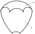
A kind of air blower that can utilize is the vacuum compression bag of power of bleeding, and be primarily characterized in that: be provided with infundibulate rubber valve (2) at the bleeding point place of vacuum compression bag (1), infundibulate rubber valve top is provided with the extension (3) that inwardly twists.Infundibulate rubber valve of the present utility model place is provided with the extension that inwardly twists, and has certain elasticity, and the air blower of no matter little admission port or big admission port can both wrap its admission port.
Advantage of the present utility model is: infundibulate rubber valve of the present utility model place is provided with the extension that inwardly twists, and has certain elasticity, and the air blower of no matter little admission port or big admission port can both wrap its admission port.
Description of drawings
Fig. 1 is constructional drawing of the present utility model;
Fig. 2 is the section-drawing of infundibulate rubber valve of the present utility model.
The specific embodiment
The utility model is described in further detail below in conjunction with the specific embodiment:
A kind of air blower that can utilize is the vacuum compression bag of power of bleeding, and be primarily characterized in that: be provided with infundibulate rubber valve (2) at the bleeding point place of vacuum compression bag (1), infundibulate rubber valve top is provided with the extension (3) that inwardly twists.Infundibulate rubber valve of the present utility model place is provided with the extension that inwardly twists, and has certain elasticity, and the air blower of no matter little admission port or big admission port can both wrap its admission port by the extension that inwardly twists of the present utility model.
Claims (1)
- One kind can to utilize air blower be to bleed the vacuum compression bag of power, be primarily characterized in that: be provided with infundibulate rubber valve (2) at the bleeding point place of vacuum compression bag (1), infundibulate rubber valve top is provided with the extension (3) that inwardly twists.
Priority Applications (1)
| Application Number | Priority Date | Filing Date | Title |
|---|---|---|---|
| CN 201320124161 CN203222202U (en) | 2013-03-19 | 2013-03-19 | Vacuum compression bag capable of using blower as suction power |
Applications Claiming Priority (1)
| Application Number | Priority Date | Filing Date | Title |
|---|---|---|---|
| CN 201320124161 CN203222202U (en) | 2013-03-19 | 2013-03-19 | Vacuum compression bag capable of using blower as suction power |
Publications (1)
| Publication Number | Publication Date |
|---|---|
| CN203222202U true CN203222202U (en) | 2013-10-02 |
Family
ID=49249214
Family Applications (1)
| Application Number | Title | Priority Date | Filing Date |
|---|---|---|---|
| CN 201320124161 Expired - Fee Related CN203222202U (en) | 2013-03-19 | 2013-03-19 | Vacuum compression bag capable of using blower as suction power |
Country Status (1)
| Country | Link |
|---|---|
| CN (1) | CN203222202U (en) |
-
2013
- 2013-03-19 CN CN 201320124161 patent/CN203222202U/en not_active Expired - Fee Related
Similar Documents
| Publication | Publication Date | Title |
|---|---|---|
| EP2549204A3 (en) | Air conditioning apparatus | |
| CN204226731U (en) | A kind of Novel pneumatic valve | |
| CN203222132U (en) | Rubber sleeve air cock capable of being used for extracting air of vacuum compression bags | |
| CN204210397U (en) | With the panel computer of sucker | |
| CN203670317U (en) | Pressure increasing device | |
| CN202704559U (en) | Vacuum suction device for glass moving machine | |
| CN203222131U (en) | Vacuum compression bag air extraction nozzle capable of being applicable to various models of blowers | |
| CN203230915U (en) | Air faucet for inflating inflatable toys through blower | |
| CN203222230U (en) | Vacuum compression bag capable of using blower as suction power | |
| CN203222130U (en) | Vacuum compression bag capable of using blower as air extraction power | |
| CN203229015U (en) | Vacuum compression bag with blower serving as pumping power | |
| CN203222134U (en) | Air extraction nozzle used for vacuum compression bag | |
| CN204364468U (en) | A kind of non-disconnectable handling silica gel suction pipe group | |
| CN203114738U (en) | Device used for being connected with air outlet of fan and air port of box body | |
| CN202252151U (en) | Vacuum tail gas non-return device | |
| CN203278507U (en) | Motor cover with radiator | |
| CN203222129U (en) | Air nozzle capable of utilizing air blower for pumping air of vacuum compression bag | |
| CN203268365U (en) | Convenient-to-fix exhaust nozzle using blower as exhaust power | |
| CN203548639U (en) | Clutch booster cylinder | |
| CN203991210U (en) | The monoblock type supply and exhaust device of the strong cold house of finish paint | |
| CN201821801U (en) | Novel fly killing device | |
| CN203268366U (en) | Exhaust nozzle capable of being conveniently fixed and using air blower as exhaust power source | |
| CN204653901U (en) | A kind of new structure of air-permeable mattress of safety cap | |
| CN204357489U (en) | A kind of motor | |
| CN204119299U (en) | With the mobile phone of silicon rubber suction cup |
Legal Events
| Date | Code | Title | Description |
|---|---|---|---|
| C14 | Grant of patent or utility model | ||
| GR01 | Patent grant | ||
| C17 | Cessation of patent right | ||
| CF01 | Termination of patent right due to non-payment of annual fee |
Granted publication date: 20131002 Termination date: 20140319 |