CN203221098U - Stamping die mechanism - Google Patents
Stamping die mechanism Download PDFInfo
- Publication number
- CN203221098U CN203221098U CN 201320101364 CN201320101364U CN203221098U CN 203221098 U CN203221098 U CN 203221098U CN 201320101364 CN201320101364 CN 201320101364 CN 201320101364 U CN201320101364 U CN 201320101364U CN 203221098 U CN203221098 U CN 203221098U
- Authority
- CN
- China
- Prior art keywords
- die
- upper die
- backing plate
- plate
- counterdie
- Prior art date
- Legal status (The legal status is an assumption and is not a legal conclusion. Google has not performed a legal analysis and makes no representation as to the accuracy of the status listed.)
- Expired - Fee Related
Links
Images
Abstract
The utility model discloses a stamping die mechanism, which comprises an upper die holder and a lower die holder, and is characterized in that the upper die holder is fixedly connected with the lower die holder through left and right shores, and the lower end of the upper die holder is connected with a base plate; the lower end of the base plate is connected with an upper die fixing plate, and the lower end of the upper die fixing plate is connected with a punch-die; and the upper die holder, the base plate and the upper die fixing plate are fixed with an upper die screw, and the tail end of the upper die screw penetrates through a discharge plate. The stamping die mechanism provided by the utility model has the advantages of simple structure, less material consumption, and simple process procedures, so that the object of high quality, high yield, low consumption and safety is achieved in the whole production of parts.
Description
Technical field
The utility model relates to a kind of mold mechanism, is specifically related to a kind of blanking die mechanism.
Background technology
The punch designs of part is according to existing working condition, take all factors into consideration the each side factor that production process is carried out smoothly that influences, rationally arrange the production process of part, according to carry out punching press towards the size of the technological parameter of part, the material that the tradition punching mechanism consumes is more, complex procedures, and Mould Machining wastes time and energy simultaneously, life-span is shorter, therefore to existing punching mechanism structure and technical improvement should be arranged.
Summary of the invention
At the technological deficiency that above-mentioned the said goods exists, the utility model provides a kind of simple in structure, material consumption is few, process is simple, the life-span is high a kind of blanking die mechanism.
Technical problem to be solved in the utility model realizes by the following technical solutions:
A kind of blanking die mechanism, comprise: upper bolster and die shoe, it is characterized in that: described upper bolster is fixedlyed connected by left and right sides dagger with die shoe, described upper bolster lower end is connected with backing plate, the lower end of described backing plate is connected with upper mould fixed plate, described upper mould fixed plate lower end connects punch-die, and described upper bolster, backing plate, upper mould fixed plate are fixed by the patrix screw, and the end of described patrix screw runs through stripper.
Described die shoe is provided with the counterdie fixed head, and described counterdie fixed head is provided with backing plate, and described backing plate is provided with die, and described die shoe, counterdie fixed head, backing plate, die run through about by described counterdie screw and guide pillar and connect as one.
In described die shoe and described counterdie fixed head, be provided with push rod, in described stripper and described upper mould fixed plate, be provided with push rod.
The beneficial effects of the utility model are: simple in structure, material consumption is few, process is simple, makes the production of whole part reach high-quality, high yield, low consumption, purpose of safety.
Description of drawings
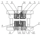
Fig. 1 is the utility model structural representation.
The specific embodiment
As shown in Figure 1: a kind of blanking die mechanism, comprise: upper bolster 1 and die shoe 2, it is characterized in that: upper bolster 1 is fixedlyed connected by left and right sides dagger 3 with die shoe 2, upper bolster 1 lower end is connected with backing plate 4, the lower end of described backing plate 4 is connected with upper mould fixed plate 5, upper mould fixed plate 5 lower ends connect punch-die 6, and described upper bolster 1, backing plate 4, upper mould fixed plate 5 are fixed by patrix screw 7, and the end of patrix screw 7 runs through stripper 8.
Die shoe 2 is provided with counterdie fixed head 9, and counterdie fixed head 9 is provided with backing plate 4, and backing plate 4 is provided with die 10, and die shoe 2, counterdie fixed head 9, backing plate 4, die 10 run through by described counterdie screw 11 and guide pillar about 12 and connect as one.
Be provided with push rod 13 in die shoe 2 and the described counterdie fixed head 9, be provided with push rod 14 in stripper 8 and the described upper mould fixed plate 5, the utility model is simple in structure, material consumption is few, process is simple, makes the production of whole part reach high-quality, high yield, low consumption, purpose of safety.
It should be noted that at last: above embodiment is only in order to illustrate the utility model and the described technical scheme of unrestricted the utility model; Therefore, those of ordinary skill in the art should be appreciated that still and can make amendment or be equal to replacement the utility model; And all do not break away from technical scheme and the improvement thereof of spirit and scope of the present utility model, and it all should be encompassed in the claim scope of the present utility model.
Claims (3)
1. blanking die mechanism, comprise: upper bolster and die shoe, it is characterized in that: described upper bolster is fixedlyed connected by left and right sides dagger with die shoe, described upper bolster lower end is connected with backing plate, the lower end of described backing plate is connected with upper mould fixed plate, described upper mould fixed plate lower end connects punch-die, and described upper bolster, backing plate, upper mould fixed plate are fixed by the patrix screw, and the end of described patrix screw runs through stripper.
2. according to the described a kind of blanking die of claim 1 mechanism, it is characterized in that: described die shoe is provided with the counterdie fixed head, described counterdie fixed head is provided with backing plate, described backing plate is provided with die, and described die shoe, counterdie fixed head, backing plate, die run through about by described counterdie screw and guide pillar and connect as one.
3. according to the described a kind of blanking die of claim 1 mechanism, it is characterized in that: in described die shoe and described counterdie fixed head, be provided with push rod, in described stripper and described upper mould fixed plate, be provided with push rod.
Priority Applications (1)
| Application Number | Priority Date | Filing Date | Title |
|---|---|---|---|
| CN 201320101364 CN203221098U (en) | 2013-03-06 | 2013-03-06 | Stamping die mechanism |
Applications Claiming Priority (1)
| Application Number | Priority Date | Filing Date | Title |
|---|---|---|---|
| CN 201320101364 CN203221098U (en) | 2013-03-06 | 2013-03-06 | Stamping die mechanism |
Publications (1)
| Publication Number | Publication Date |
|---|---|
| CN203221098U true CN203221098U (en) | 2013-10-02 |
Family
ID=49248115
Family Applications (1)
| Application Number | Title | Priority Date | Filing Date |
|---|---|---|---|
| CN 201320101364 Expired - Fee Related CN203221098U (en) | 2013-03-06 | 2013-03-06 | Stamping die mechanism |
Country Status (1)
| Country | Link |
|---|---|
| CN (1) | CN203221098U (en) |
Cited By (3)
| Publication number | Priority date | Publication date | Assignee | Title |
|---|---|---|---|---|
| CN104307969A (en) * | 2013-06-28 | 2015-01-28 | 吴小再 | Stamping die |
| CN104438555A (en) * | 2013-06-28 | 2015-03-25 | 吴小再 | Blanking die and braking method thereof |
| CN104438556A (en) * | 2013-06-28 | 2015-03-25 | 吴小再 | Blanking die capable of achieving emergency braking |
-
2013
- 2013-03-06 CN CN 201320101364 patent/CN203221098U/en not_active Expired - Fee Related
Cited By (8)
| Publication number | Priority date | Publication date | Assignee | Title |
|---|---|---|---|---|
| CN104307969A (en) * | 2013-06-28 | 2015-01-28 | 吴小再 | Stamping die |
| CN104438555A (en) * | 2013-06-28 | 2015-03-25 | 吴小再 | Blanking die and braking method thereof |
| CN104438556A (en) * | 2013-06-28 | 2015-03-25 | 吴小再 | Blanking die capable of achieving emergency braking |
| CN104475535A (en) * | 2013-06-28 | 2015-04-01 | 吴小再 | Punching die with braking function and working method thereof |
| CN104307969B (en) * | 2013-06-28 | 2016-03-23 | 中国石油大学(华东) | A kind of blanking die |
| CN104475535B (en) * | 2013-06-28 | 2016-05-25 | 东莞理工学院 | There is blanking die and the method for work thereof of braking function |
| CN104438556B (en) * | 2013-06-28 | 2016-08-17 | 泰州市安腾轴皮厂(集团) | A kind of can the blanking die of brake hard |
| CN104438555B (en) * | 2013-06-28 | 2016-08-24 | 东普雷(佛山)汽车部件有限公司 | Blanking die and braking method thereof |
Similar Documents
| Publication | Publication Date | Title |
|---|---|---|
| CN203304417U (en) | Flip-over type piercing and blanking die | |
| CN203221098U (en) | Stamping die mechanism | |
| CN202779355U (en) | Combination tool for forming of long box-like workpieces | |
| CN103624151A (en) | Novel progressive die | |
| CN203245263U (en) | High-precision bending forming mould for elastic piece | |
| CN203044652U (en) | Novel progressive die | |
| CN202239180U (en) | Continuous mold for shell | |
| CN202427821U (en) | Stamping mold with rapid replacing type stamping head | |
| CN104384340A (en) | Combined drawing die of outside plate on front portion of edge beam of engine compartment | |
| CN204220660U (en) | Two-chip type structure hot-extrusion mold | |
| CN203541286U (en) | Reinforced blanking-punching compound die | |
| CN202803937U (en) | Novel progressive die | |
| CN203221107U (en) | Inverted type compound die structure | |
| CN203235772U (en) | Spline type gear cold-extruded one-step molding device | |
| CN202984555U (en) | Piston production mold for friction press | |
| CN204294761U (en) | The anterior outside plate drawing die of composite engine storehouse side bar | |
| CN202278063U (en) | Blanking die | |
| CN201659176U (en) | Pressing die device for arc bending machine | |
| CN203221127U (en) | Blanking-drawing compound die structure | |
| CN202219287U (en) | Pressing die for elevator counterweight | |
| CN203887036U (en) | Drawing die structure of single-action press for automobile covering part | |
| CN203061652U (en) | Floating type up-and-down hydraulic punching mechanism | |
| CN204159759U (en) | Spindle nose cover casted die mould | |
| CN103624152A (en) | Die used for punching tiny hole in thick material | |
| CN203061644U (en) | Washer blanking die set |
Legal Events
| Date | Code | Title | Description |
|---|---|---|---|
| C14 | Grant of patent or utility model | ||
| GR01 | Patent grant | ||
| CF01 | Termination of patent right due to non-payment of annual fee |
Granted publication date: 20131002 Termination date: 20150306 |
|
| EXPY | Termination of patent right or utility model |