The ventilation of transformer room device
Technical field
The utility model relates to a kind of ventilation unit, relates in particular to a kind of ventilation of transformer room device.
Background technology
At present, the transformer room generally adopts the bottom, gate to establish air-inlet window, and ventilation window is established on top, roof or exhaust blower ventilates.Along with the concentrated growth of power loads such as air-conditioning, oil type transformer caloric value is also sharply soaring, only depends on natural draft to be difficult to satisfy radiating requirements during summer high temperature.If it is overheated that transformer continues for a long time, can cause insulation degradation, even develop into electric arc point hot in nature and cause device damage.
Summary of the invention
The purpose of this utility model provides a kind of ventilation of transformer room device that improves drafting efficiency.
For achieving the above object, the technical scheme that adopts of the utility model is:
A kind of ventilation of transformer room device, comprising: ground, the transformer room above the ground is installed, transformer is installed in the transformer room, and the top of transformer room is equipped with roof extract unit, on the exterior wall of transformer room forced draft fan is installed, attemperating unit is installed on the forced draft fan, its characteristics are: described ground is equipped with ventilation duct, and it is corresponding with transformer that ventilation duct is positioned at the below of transformer, and forced draft fan is installed in the ventilation duct.
According to described ventilation of transformer room device, its characteristics are: described ventilation duct can arrange one or more according to the size of transformer room.
According to described ventilation of transformer room device, its characteristics are: the material of described ventilation duct is glass fibre reinforced plastic blast pipe, and the inside of ventilation duct has can regulate air outlet.
The utility model has the advantages that: the utility model is by adopting forced draft fan air-supply and exhaust blower air draft, the whole mode of using effectively raises the efficient of transformation chamber ventilated, the radiator of air-cooled direct cistron transformer, good heat dissipation effect, control intellectuality, reduced the indoor problem of transformation, stop the potential safety hazard brought by the temperature height, prolonged service life of equipment.
Description of drawings
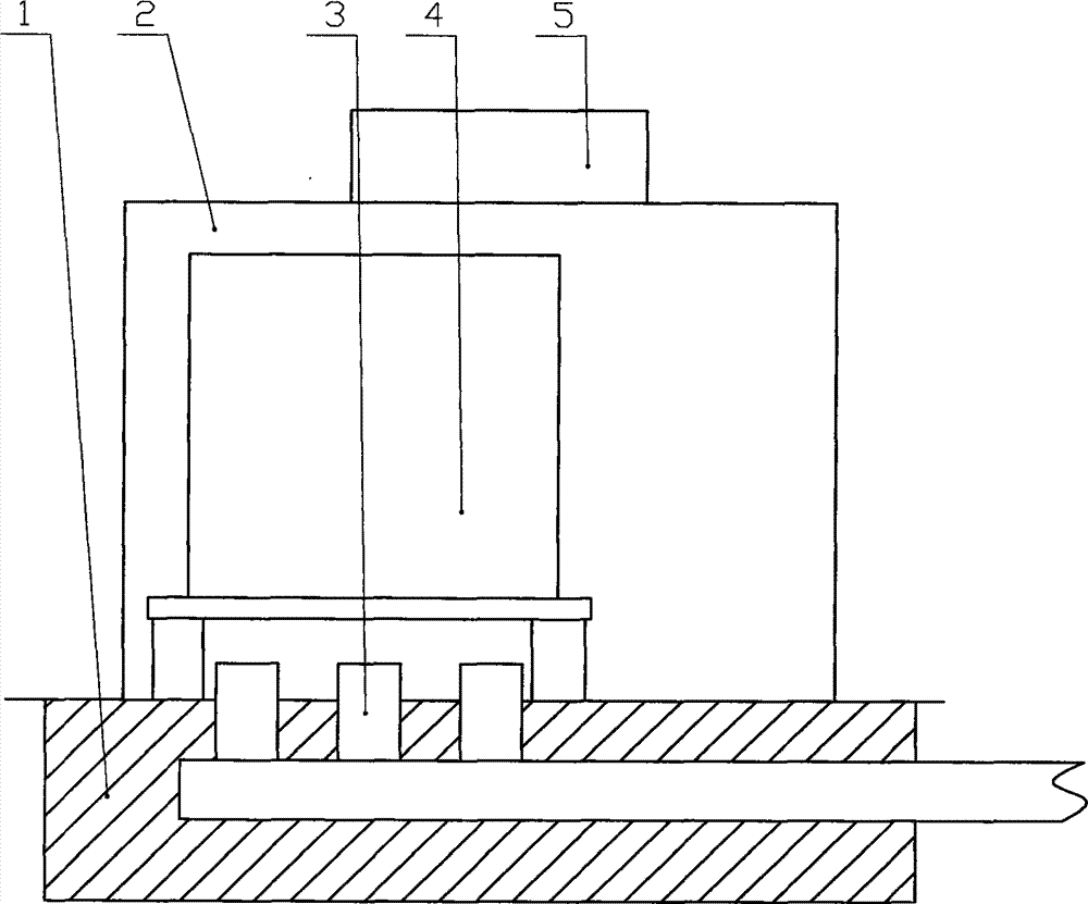
Fig. 1 is the utility model structural representation.
In the accompanying drawing
1, ground; 2, transformer room; 3, ventilation duct; 4, transformer; 5, exhaust blower.
Embodiment
Below in conjunction with accompanying drawing and specific embodiment the utility model is further described:
A kind of ventilation of transformer room device, as shown in Figure 1, comprising: ground 1,1 top, ground is equipped with transformer room 2, and transformer 4 is installed in the transformer room 2, the top of transformer room 2 is equipped with roof extract unit 5, on the exterior wall of transformer room 2 forced draft fan is installed, attemperating unit is installed on the forced draft fan, described ground 1 is equipped with ventilation duct 3, it is corresponding with transformer 4 that ventilation duct 3 is positioned at the below of transformer 4, in the ventilation duct 3 forced draft fan is installed.
Described ventilation duct 3 can arrange one or more according to the size of transformer room 2 in the present embodiment.
The material of described ventilation duct 3 is glass fibre reinforced plastic blast pipe in the present embodiment, and the inside of ventilation duct 3 has can regulate air outlet.
The utility model beneficial effect: the utility model is by adopting forced draft fan air-supply and exhaust blower air draft, the whole mode of using effectively raises the efficient of transformation chamber ventilated, reduce the indoor problem of transformation, stopped the potential safety hazard brought by the temperature height, prolonged service life of equipment.
Embodiment recited above is described preferred implementation of the present utility model; be not that design of the present utility model and protection range are limited; under the prerequisite that does not break away from the utility model design concept; common engineers and technicians make the technical solution of the utility model in this area various modification and improvement all should fall into protection range of the present utility model.