CN203214918U - Local valve body replaceable long-service life gate valve - Google Patents
Local valve body replaceable long-service life gate valve Download PDFInfo
- Publication number
- CN203214918U CN203214918U CN 201320234964 CN201320234964U CN203214918U CN 203214918 U CN203214918 U CN 203214918U CN 201320234964 CN201320234964 CN 201320234964 CN 201320234964 U CN201320234964 U CN 201320234964U CN 203214918 U CN203214918 U CN 203214918U
- Authority
- CN
- China
- Prior art keywords
- valve body
- valve
- plate
- gate
- pilot hole
- Prior art date
- Legal status (The legal status is an assumption and is not a legal conclusion. Google has not performed a legal analysis and makes no representation as to the accuracy of the status listed.)
- Expired - Fee Related
Links
- 238000007789 sealing Methods 0.000 claims abstract description 7
- 230000003044 adaptive effect Effects 0.000 claims description 3
- 230000001105 regulatory effect Effects 0.000 claims description 3
- 239000007788 liquid Substances 0.000 claims description 2
- 230000015572 biosynthetic process Effects 0.000 claims 1
- 230000002035 prolonged effect Effects 0.000 abstract 1
- 239000012530 fluid Substances 0.000 description 2
- 238000000034 method Methods 0.000 description 2
- TVEXGJYMHHTVKP-UHFFFAOYSA-N 6-oxabicyclo[3.2.1]oct-3-en-7-one Chemical compound C1C2C(=O)OC1C=CC2 TVEXGJYMHHTVKP-UHFFFAOYSA-N 0.000 description 1
- RYGMFSIKBFXOCR-UHFFFAOYSA-N Copper Chemical compound [Cu] RYGMFSIKBFXOCR-UHFFFAOYSA-N 0.000 description 1
- 229910000831 Steel Inorganic materials 0.000 description 1
- 239000000956 alloy Substances 0.000 description 1
- 229910045601 alloy Inorganic materials 0.000 description 1
- 230000009286 beneficial effect Effects 0.000 description 1
- 238000005266 casting Methods 0.000 description 1
- 238000010586 diagram Methods 0.000 description 1
- 239000003814 drug Substances 0.000 description 1
- 230000007613 environmental effect Effects 0.000 description 1
- 239000012467 final product Substances 0.000 description 1
- 238000005272 metallurgy Methods 0.000 description 1
- 239000010959 steel Substances 0.000 description 1
- 238000009941 weaving Methods 0.000 description 1
Images

Landscapes
- Sliding Valves (AREA)
Abstract
The utility model discloses a local valve body replaceable long-service life gate valve. The gate valve comprises a valve body (1) and a valve plate (2), wherein the valve plate (2) is located inside the valve body (1), a yield hole matched with the valve plate (2) is formed in a seat of the valve body (1), a close plate (3) for closing the yield hole is arranged on the yield hole, and is connected with the valve body (1) through a connecting device. According to the gate valve disclosed by the utility model, the stroke of the close plate is adjusted to prevent the wear on the sealing valve body and the valve seat caused by overlarge opening and closing force in an opening force of the valve plate; simultaneously, the service life of the gate valve can be prolonged by replacing the close plate.
Description
Technical field
The utility model relates to gate valve, especially relates to the valve body of gate valve.
Background technique
Gate valve is one of most widely used valve in the various fluid conveying engineerings, uses as cut-off device on the fluid pipe-line of industries such as building, urban environmental protection, petrochemical industry, medicine, food, metallurgy, weaving, electric power.The tradition Gate-valve sealing is bad, hard seal gate valve particularly, and the seal valve seat between valve body, the valve plate generally all is Cuprum alloy, not during complete shut-down, sealing surface of valve plate wearing and tearing or damage are all very serious at gate valve.The wear extent that valve body, valve plate seal valve seat move up and down is big, and Gate-valve sealing was lost efficacy, and valve body, valve plate shorten working life greatly.
The model utility content
The purpose of this utility model is to solve traditional gate valve body, valve plate and valve seat to cause short problem in working life because of wearing and tearing.
For addressing the above problem, the technical solution adopted in the utility model is: valve body local replacing formula long lifetime gate valve, comprise valve body and the valve plate that is positioned at valve body, the valve body that it is characterized in that described valve plate below is provided with the yielding hole adaptive with valve plate, below, described yielding hole is provided with the shrouding of making a concession the hole for shutoff, and described shrouding connects valve body by connection set.
Above-mentioned connection set comprises the fixed base that is connected with valve body, described fixed base is provided with pilot hole, the outer end of pilot hole is screw, be provided with adjustable lever in the pilot hole, adjustable lever one end and shrouding are connected, the other end adjusting bolt that is threaded, the outer end screw scyewed joint of regulating bolt and pilot hole.
The beneficial effects of the utility model are: by the stroke adjustment of bolt to shrouding, can prevent effectively that valve plate is in the process of opening, because of the excessive wearing and tearing to sealed valve body and valve seat of hoisting capacity; Simultaneously by changing the working life that shrouding can prolong gate valve greatly.
Description of drawings
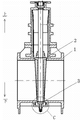
Fig. 1 is the utility model schematic representation.
Fig. 2 is C place enlarged diagram among Fig. 1.
Shown in the figure: 1 valve body, 2 valve plates, 3 shroudings, 7 adjustable levers, 8 fixed bases, 9 regulate bolt, 10 seal rings.
Embodiment
Below in conjunction with Fig. 1 and Fig. 2, select preference that the utility model is described further.
As shown in Figure 1 and Figure 2, valve body local replacing formula long lifetime gate valve, comprise valve body 1 and the valve plate 2 that is positioned at valve body 1, offer the yielding hole adaptive with valve plate 2 on valve body 1 base, make a concession the hole and be positioned at valve plate 2 belows, make a concession the below, hole and be provided with the shrouding 3 of making a concession the hole for shutoff, shrouding 3 is steel plate, shrouding 3 connects on the valve body 1 by connection set, and shrouding 3 is positioned.When wearing and tearing with valve plate 2, shrouding 3 can change shrouding 3, thus the working life of realizing the prolongation gate valve.Connection set can have multiple mode, can be to be welded on the valve body 1, and can be to be riveted on the valve body, can be connected on the valve body 1 by bolt, also can be that other modes connect.The connection set of present embodiment as shown in Figure 2, it comprises the fixed base 8 that is connected with valve body, it is that casting is connected as a single entity in the time of also can producing with valve body 1 that fixed base 8 can be welded on valve body 1, fixed base 8 is provided with pilot hole, the outer end of pilot hole is tapped hole, pilot hole is positioned at the below of making a concession the hole, be provided with adjustable lever 7 in the pilot hole, adjustable lever 7 can be shifted up and down along pilot hole, adjustable lever 7 one ends and shrouding 3 are connected, the other end is threaded and regulates bolt 9, the outer end screw scyewed joint of regulating bolt and pilot hole.Be provided with the seal ring 10 for liquid sealing between adjustable lever 7 and the fixed base pilot hole, prevent medium remittance leakage.
The utility model is work like this: when shrouding leaks because wearing and tearing produce, rotating bolt 9 makes adjustable lever 7 drive shrouding 3 and moves up in the vertical direction, reaches and adjusts valve plate 2 to the stroke between the valve body 1, thereby make the local replacing of valve body, prolong the working life of valve body.The travel position of adjusting adjustable lever when gate valve assembles gets final product.If wearing and tearing cause sealing to go wrong, only need to adjust the shrouding position or change shrouding.
Claims (4)
1. valve body local replacing formula long lifetime gate valve, comprise valve body (1) and be positioned at the valve plate (2) of valve body, the valve body (1) that it is characterized in that described valve plate (2) below is provided with the yielding hole adaptive with valve plate (2), below, described yielding hole is provided with the shrouding (3) of making a concession the hole for shutoff, and described shrouding (3) connects valve body (1) by connection set.
2. valve body local replacing formula long lifetime gate valve according to claim 1, it is characterized in that described connection set comprises the fixed base (8) that is connected with valve body, described fixed base (8) is provided with pilot hole, the outer end of pilot hole is screw, be provided with adjustable lever (7) in the pilot hole, adjustable lever (7) one ends and shrouding (3) are connected, and the other end is threaded and regulates bolt (9), the outer end screw scyewed joint of regulating bolt (9) and pilot hole.
3. valve body local replacing formula long lifetime gate valve according to claim 2 is characterized in that described fixed base (8) and valve body (1) the formation Seal cage that is connected as a single entity.
4. according to claim 2 or 3 described valve body local replacing formula long lifetime gate valves, it is characterized in that being provided with between described adjustable lever (7) and the fixed base pilot hole (8) seal ring (10) for liquid sealing.
Priority Applications (1)
| Application Number | Priority Date | Filing Date | Title |
|---|---|---|---|
| CN 201320234964 CN203214918U (en) | 2013-05-03 | 2013-05-03 | Local valve body replaceable long-service life gate valve |
Applications Claiming Priority (1)
| Application Number | Priority Date | Filing Date | Title |
|---|---|---|---|
| CN 201320234964 CN203214918U (en) | 2013-05-03 | 2013-05-03 | Local valve body replaceable long-service life gate valve |
Publications (1)
| Publication Number | Publication Date |
|---|---|
| CN203214918U true CN203214918U (en) | 2013-09-25 |
Family
ID=49204457
Family Applications (1)
| Application Number | Title | Priority Date | Filing Date |
|---|---|---|---|
| CN 201320234964 Expired - Fee Related CN203214918U (en) | 2013-05-03 | 2013-05-03 | Local valve body replaceable long-service life gate valve |
Country Status (1)
| Country | Link |
|---|---|
| CN (1) | CN203214918U (en) |
-
2013
- 2013-05-03 CN CN 201320234964 patent/CN203214918U/en not_active Expired - Fee Related
Similar Documents
| Publication | Publication Date | Title |
|---|---|---|
| CN204628570U (en) | Multi-layer sealed Multifunctional stop valve | |
| CN108105420A (en) | A kind of high-pressure hydraulic pump discharge control valve | |
| CN203730785U (en) | Plate sealing dual-eccentric flange flexible sealing butterfly valve | |
| CN202992205U (en) | Low load type cutting-off butterfly valve | |
| CN204647338U (en) | Nuclear island Y shape adds pipe arrangement High Temperature High Pressure pressure-relief type Double-clack stop valve | |
| CN201330855Y (en) | Anti-friction valve | |
| CN201121721Y (en) | Three-eccentric metal sealing butterfly valve | |
| CN203384402U (en) | Ultra-high-temperature hard seal ball valve | |
| CN203009883U (en) | Forged-steel solid high-pressure sluice valve | |
| CN207349476U (en) | A kind of wedge action valve | |
| CN105065701A (en) | Hard sealing lifting type brake plug valve and control method thereof | |
| CN204312721U (en) | The seal butterfly valve of a kind of band half spherical arc shape butterfly plate | |
| CN203979457U (en) | A kind of gate valve | |
| CN204312724U (en) | A kind of multi-functional butterfly valve | |
| CN202215756U (en) | High-temperature high-pressure stop valve | |
| CN204099659U (en) | Duplex three-way valve | |
| CN204312723U (en) | The butterfly valve of a kind of band half spherical arc shape butterfly plate | |
| CN204312717U (en) | A kind of hemisphere arc valve | |
| CN100529486C (en) | Large-caliber high-pound-grade alloy steel gate valve | |
| CN204042064U (en) | External regulation type pretension ball valve | |
| CN205173531U (en) | Knife gate valve | |
| CN104048053A (en) | Four-eccentric two-way pressure butterfly valve with elliptical sealing surface | |
| CN204387375U (en) | High temperature super abrasive anti-coking flap type | |
| CN204312737U (en) | The adjustment butterfly valve of a kind of band half spherical arc shape butterfly plate | |
| CN203348564U (en) | Large-diameter double-valve-flap pressure relief throttling valve |
Legal Events
| Date | Code | Title | Description |
|---|---|---|---|
| C14 | Grant of patent or utility model | ||
| GR01 | Patent grant | ||
| C56 | Change in the name or address of the patentee |
Owner name: ANHUI TONGDU FLOW TECHNOLOGY CO., LTD. Free format text: FORMER NAME: ANHUI TONGDU VALVE CO., LTD. |
|
| CP01 | Change in the name or title of a patent holder |
Address after: 244000 Anhui city in Tongling Province, north mountain lion Copper Road No. 188 Patentee after: ANHUI TONGDU FLOW TECHNOLOGY Co.,Ltd. Address before: 244000 Anhui city in Tongling Province, north mountain lion Copper Road No. 188 Patentee before: ANHUI TONGDU VALVE Co.,Ltd. |
|
| CF01 | Termination of patent right due to non-payment of annual fee |
Granted publication date: 20130925 |
|
| CF01 | Termination of patent right due to non-payment of annual fee |