The slide rail combined type is not found five the machining center machines that crouch altogether
Technical field
The utility model relates to the machining center machine, refers to that especially a kind of whole height is minimized, and then is conducive to upright five the machining center machines that crouch of slide rail combined type that are not total to of production and assembly.
Background technology
The machining center machine is the facility that industry is widely used in workpiece processing, and it has distinguished horizontal, vertical at the difference of main tapping configuration and three kinds of horizontal-vertical double-purposes.
See also shown in Figure 6, the horizontal Machining centers machine of prior art, its primary structure is to be set with a column 71 in the end face rear side place of a base 70, the leading flank of this column 71 is provided with at least one vertical slide rail 711, one horizontal main axis head 72 can slide along this vertical slide rail 711, this horizontal main axis head 72 has a horizontal main axis 721, this horizontal main axis 721 can be along the horizontal direction stretching motion, and the end clips of horizontal main axis 721 is held a cutter (not shown), place, the end face front side of this base 70 is provided with a workbench 73 again, add man-hour when using the horizontal Machining centers machine to carry out workpiece, the workpiece placement positioning on workbench 73, and can be processed the circumferential surface of workpiece by the cutter of horizontal main axis 721 clampings.
See also shown in Figure 7, the vertical machining centre machine of prior art, its primary structure is to be set with a column 81 in the end face rear side place of a base 80, the leading flank of this column 81 is provided with at least one vertical slide rail 811, one vertical spindle head 82 can slide along this vertical slide rail 811, this vertical spindle head 82 has a vertical spindle 821, this vertical spindle 821 can be along the vertical direction stretching motion, and the end clips of vertical spindle 821 is held a cutter (not shown), place, the end face front side of this base 80 is provided with a workbench 83 again, add man-hour when using the vertical machining centre machine to carry out workpiece, the workpiece placement positioning on workbench 83, and can be processed the end face of workpiece by the cutter of vertical spindle 821 clampings.
See also shown in Figure 8, be M340130 number " coaxial line is slide rail horizontal-vertical double-purpose machining center machine altogether " novel patent case of TaiWan, China notification number, its primary structure is to be set with a column 91 in the end face rear side place of a base 90, the leading flank of this column 91 is provided with at least one vertical slide rail 911, one horizontal main axis head 92 and a vertical spindle head 93 can slide along this vertical slide rail 911, and 92 on horizontal main axis head is below vertical spindle head 93, horizontal-vertical double-purpose machining center machine is incorporated into horizontal main axis head 92 and vertical spindle head 93 on the same facility, so being different from horizontal Machining centers machine or vertical machining centre machine only can process circumferential surface or the end face of workpiece, horizontal-vertical double-purpose machining center machine can be processed circumferential surface and the end face of workpiece, and then makes working (machining) efficiency obtain to promote.
Yet above-mentioned horizontal-vertical double-purpose machining center machine still has following shortcoming when reality is used:
1. horizontal main axis head 92 shares vertical slide rail 911 with vertical spindle head 93, so vertical slide rail 911 must have certain length, just can make horizontal main axis head 92 and vertical spindle head 93 have enough sliding strokes to be beneficial to process the carrying out of operation, but therefore cause the height of the column 91 that is provided with this vertical slide rail 911 to reduce, and cause the inconvenience in the production and assembly.
2. 92 on horizontal main axis head is below vertical spindle head 93, adds the iron filings that produce man-hour and is very easy to fall to horizontal main axis head 92 so use vertical spindle head 92 to carry out workpiece, and influence the machining accuracy of horizontal main axis head 92.
The utility model content
Shortcoming in view of aforementioned prior art, the purpose of this utility model is: a kind of upright five machining center machines that crouch of slide rail combined type that are not total to are provided, by horizontal main axis head and vertical spindle head are designed to not share slide rail, make the whole height of machining center machine be minimized, and then be conducive to production and assembly.
For reaching aforesaid utility model purpose, upright five the machining center machines that crouch of slide rail combined type that are not total to that the utility model is designed, it includes a body, one horizontal main axis head, one vertical spindle head and a workbench assembly, wherein: this body has a base, the end face rear side place of this base is set with a column, the leading flank of this column is provided with at least one first vertical slide rail, the end face of column is set with a footstock, the front end of this footstock protrudes from the leading flank of column and extends to be formed with a department of assembly downwards, be formed with a clearance space between this department of assembly and the column, the leading flank of department of assembly is provided with at least one second vertical slide rail, and second position of described second vertical slide rail is in the place ahead of the first half of described first vertical slide rail; This horizontal main axis head can slide along described first vertical slide rail, and this horizontal main axis head has a horizontal main axis, and this horizontal main axis can be along the horizontal direction stretching motion; This vertical spindle head can slide along described second vertical slide rail, and this vertical spindle head has a vertical spindle, and this vertical spindle can be along the vertical direction stretching motion; This workbench assembly can be arranged at the place, end face front side of described base horizontally slidingly.
Described upright five the machining center machines that crouch of slide rail combined type that are not total to, wherein: the leading flank of this column is provided with one first ball driving screw, the top of this first ball driving screw is provided with one first drive unit, this first drive unit is used for driving the described first ball driving screw, and this horizontal main axis head is to drive and be able to along described first vertical slide rail slip by the described first ball driving screw; The leading flank of the department of assembly of this footstock is provided with one second ball driving screw, the top of this second ball driving screw is provided with one second drive unit, this second drive unit is used for driving the described second ball driving screw, and this vertical spindle head is to drive and be able to along described second vertical slide rail slip by the described second ball driving screw.
Described upright five the machining center machines that crouch of slide rail combined type that are not total to, wherein this workbench assembly has a workbench that can rotate.
Described upright five the machining center machines that crouch of slide rail combined type that are not total to, it further includes a horizontal tool magazine and a vertical tool magazine, and this horizontal tool magazine is configured in a side of described column, and this vertical tool magazine is configured in a side of the department of assembly of described footstock.
Described upright five the machining center machines that crouch of slide rail combined type that are not total to, wherein the leading flank lateral separation of this column is provided with two described first vertical slide rail, and the leading flank lateral separation of the department of assembly of this footstock is provided with two described second vertical slide rail.
Described upright five the machining center machines that crouch of slide rail combined type that are not total to, wherein said two first vertical slide rail are respectively solid memder, and described two second vertical slide rail are made up of spaced a plurality of members respectively.
Upright five the machining center machines that crouch of slide rail combined type that are not total to provided by the utility model, advantage and the beneficial effect that can obtain comprise at least:
1. horizontal main axis head and vertical spindle head do not share slide rail, first vertical slide rail that is arranged at column provides the horizontal main axis head required stroke that slides, second vertical slide rail that is arranged at footstock provides the vertical spindle head required stroke that slides, and first vertical slide rail and second vertical slide rail have part to overlap in lengthwise position, therefore, the whole height of column and footstock can be lower than the height of the single column of prior art, and then is conducive to production and assembly.
2. use the vertical spindle head to carry out workpiece and add man-hour, the horizontal main axis head is adjusted to propradation, and the iron filings that produce fall to the horizontal main axis head and the machining accuracy that influences the horizontal main axis head so can avoid processing.
Description of drawings
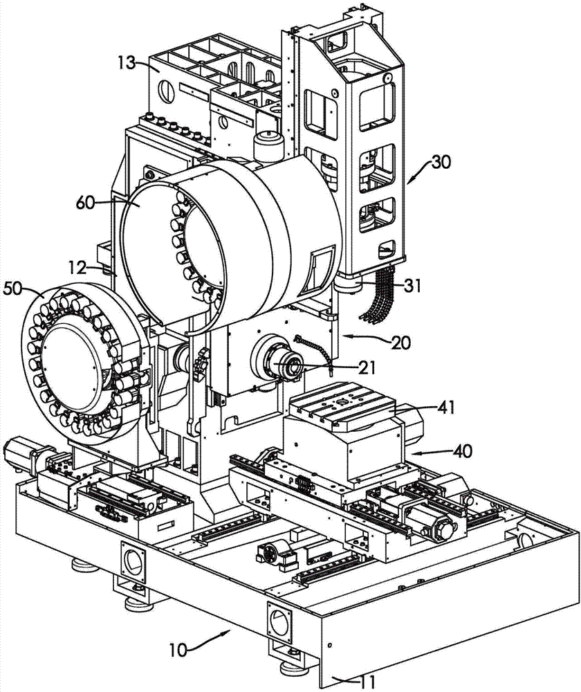
Fig. 1 is stereo appearance figure of the present utility model.
Fig. 2 is another angle stereo appearance figure of the present utility model.
Fig. 3 is column of the present utility model and footstock stereo appearance figure.
Fig. 4 is that horizontal main axis head of the present utility model uses side view of the state.
Fig. 5 is that vertical spindle head of the present utility model uses side view of the state.
Fig. 6 is the horizontal Machining centers machine stereo appearance figure of prior art.
Fig. 7 is the vertical machining centre machine stereo appearance figure of prior art.
Fig. 8 is the horizontal-vertical double-purpose machining center machine stereo appearance figure of prior art.
Symbol description among the figure
10 bodies, 11 bases
12 columns, 121 first vertical slide rail
122 first ball driving screws, 123 first drive units
13 footstocks, 131 departments of assembly
132 second vertical slide rail, 133 second ball driving screws
134 second drive units, 20 horizontal main axis heads
21 horizontal main axis, 30 vertical spindle heads
31 vertical spindles, 40 workbench assemblies
41 workbench, 50 horizontal tool magazines
60 vertical tool magazine 70 bases
71 columns, 711 vertical slide rail
72 horizontal main axis heads, 721 horizontal main axis
73 workbench, 80 bases
81 columns, 811 vertical slide rail
82 vertical spindle heads, 821 vertical spindles
83 workbench, 90 bases
91 columns, 911 vertical slide rail
92 horizontal main axis heads, 93 vertical spindle heads.
The specific embodiment
See also Figure 1 and Figure 2, upright five the machining center machines that crouch of slide rail combined type that are not total to of the present utility model, it includes a body 10, a horizontal main axis head 20, a vertical spindle head 30, a workbench assembly 40, a horizontal tool magazine 50 and a vertical tool magazine 60.
This body 10 has a base 11, the end face rear side place of this base 11 is set with a column 12, please cooperate consult shown in Figure 3, the leading flank of this column 12 is provided with at least one first vertical slide rail 121 and one first ball driving screw 122, the top of this first ball driving screw 122 is provided with one first drive unit 123, this first drive unit 123 is used for driving the first ball driving screw 122, the end face of column 12 is set with a footstock 13, the front end of this footstock 13 protrudes from the leading flank of column 12 and extends to be formed with a department of assembly 131 downwards, be formed with a clearance space between this department of assembly 131 and the column 12, the leading flank of department of assembly 131 is provided with at least one second vertical slide rail 132 and one second ball driving screw 133, second position of this second vertical slide rail 132 is in the place ahead of the first half of first vertical slide rail 121, the top of this second ball driving screw 133 is provided with one second drive unit 134, and this second drive unit 134 is used for driving the second ball driving screw 133.
Specific embodiment shown in the figure, the leading flank lateral separation of this column 12 is provided with two first vertical slide rail 121, described two first vertical slide rail 121 are respectively solid memder, the leading flank lateral separation of the department of assembly 131 of this footstock 13 is provided with two second vertical slide rail 132, and described two second vertical slide rail 132 are made up of spaced a plurality of members respectively.
This horizontal main axis head 20 is to be driven and be able to along first vertical slide rail 121 carry out sliding up and down of vertical direction by the first ball driving screw 122, this horizontal main axis head 20 has a horizontal main axis 21, this horizontal main axis 21 can be along the horizontal direction stretching motion, and the end clips of horizontal main axis 21 is held a cutter (not shown).
This vertical spindle head 30 is to be driven and be able to along second vertical slide rail 132 carry out sliding up and down of vertical direction by the second ball driving screw 133, this vertical spindle head 30 has a vertical spindle 31, this vertical spindle 31 can be along the vertical direction stretching motion, and the end clips of vertical spindle 31 is held a cutter (not shown).
This workbench assembly 40 can be arranged at the place, end face front side of base 11 horizontally slidingly, this workbench assembly 40 has a rotatable workbench 41, this horizontal tool magazine 50 is configured in a side of column 12, and this vertical tool magazine 60 is configured in a side of the department of assembly 131 of footstock 13.
The composition member of aforesaid horizontal main axis head 20, vertical spindle head 30, workbench assembly 40, horizontal tool magazine 50 and vertical tool magazine 60 is prior art, therefore no longer adds to give unnecessary details.
See also shown in Figure 4, the circumferential surface that desire uses horizontal main axis head 20 to carry out workpiece adds man-hour, with the workpiece placement positioning on the workbench 41 of workbench assembly 40, and vertical spindle head 30 is adjusted into propradation, make vertical spindle 31 away from workpiece, horizontal main axis head 20 is adjusted into the decline state, makes horizontal main axis 21 near workpiece, and then by the cutter of horizontal main axis 21 clampings the circumferential surface of workpiece is processed.
See also shown in Figure 5, the end face that desire uses vertical spindle head 30 to carry out workpiece adds man-hour, with the workpiece placement positioning on the workbench 41 of workbench assembly 40, and horizontal main axis head 20 is adjusted into propradation and is placed in clearance space between the department of assembly 131 of column 12 and footstock 13, and horizontal main axis 21 is away from workpiece, vertical spindle head 30 is adjusted into the decline state, make vertical spindle 31 near workpiece, and then by the cutter of vertical spindle 31 clampings the end face of workpiece is processed, because the horizontal main axis head 20 of this moment is propradation, the iron filings that produce man-hour fall to horizontal main axis head 20 and the machining accuracy that influences horizontal main axis head 20 so can avoid adding.
By the use of horizontal main axis head 20 and vertical spindle head 30, can process circumferential surface and the end face of workpiece, and cooperate 41 rotations of control workbench, can process to reach five processing effects to end face and four sides of workpiece.
Characteristics of the present utility model are, horizontal main axis head 20 does not share slide rail with vertical spindle head 30, first vertical slide rail 121 that is arranged at column 12 provides 20 slips of horizontal main axis head required stroke, second vertical slide rail 132 that is arranged at footstock 13 provides 30 slips of vertical spindle head required stroke, and first vertical slide rail 121 and second vertical slide rail 132 have part to overlap in lengthwise position, therefore, column 12 is minimized with the whole height of footstock 13, and then is conducive to production and assembly.