Transformer high-voltage bushing lead-in wire draw-gear
Technical field
The utility model relates to a kind of maintenance tooling device of transformer, particularly relates to a kind of transformer high-voltage bushing lead-in wire draw-gear.
Background technology
In recent years, along with improving constantly that the operation of power networks stabilization of equipment performance is required, grid maintenance Condition Based Maintenance Putting in Practice particularly, increasing to work such as transformer regular maintenance, maintenance and overhauls, standardized work has also proposed Secretary to the maintenance technique of transformer.In the bushing shell for transformer installation process, traditional mounting means is to hitch the sleeve pipe lead-in wire with pull rope one end, when sleeve pipe is in place, by the mode that pulls the sleeve pipe lead riser is pulled out, sleeve pipe top insulator partly is subjected to the restriction of mechanical strength simultaneously, can not use the heavy mechanical equipments such as crane, can only use the method for artificial pulling, there is following shortcoming in this working method:
1) fail safe is not high, poor reliability.The winding outlet is easy to rub with internal surface of sleeve pipe in the pulling process, causes sleeve pipe lead-in wire damage, in potential safety hazards such as easy appearance heating in service, discharge in the future, reduces the operational reliability of transformer.
2) consume a large amount of man-hours, efficiency is low.Traditional mounting means is consuming time longer, and the installation of single sleeve pipe needs 30-40 minute, and operating efficiency is very low.
3) labour intensity is larger, expends a large amount of manpowers.6-7 personnel's mounting sleeve adds crane commanding, monitoring personnel etc., needs nearly 10 staff.
Summary of the invention
In order to solve the problems of the technologies described above, the utility model provides a kind of transformer high-voltage bushing lead-in wire draw-gear, makes the mechanization of sleeve pipe lead-in wire distraction procedure, saves in a large number the construction task of finishing of manpower, the quick high-quality of energy, satisfy the requirement of complex working conditions construction, avoid the damage of sleeve pipe lead-in wire.
For this reason, the technical solution of the utility model is as follows:
A kind of transformer high-voltage bushing lead-in wire draw-gear is comprised of analog bracket, drive transmission and braking stopping means; Described analog bracket comprises pedestal, fixed head and connecting axle, described fixed head is fixed on the described pedestal, described fixed head has two and be fixedly connected with by connecting axle between the two, described fixed head one end is provided with fixing hole, be used for being connected with external equipment, prevent the in use stressed rear movement of transformer high-voltage bushing lead-in wire draw-gear; Described drive transmission comprises gear train, rocking arm and steel wire rope capstan winch, drives described gear train by described rocking arm and rotates, and then drive described steel wire rope capstan winch rotation; Described braking stopping means comprises braked wheel, brake bar and stop-nut, and described braked wheel and described steel wire rope capstan winch rotate synchronously, and described brake bar is installed on the described fixed head by described stop-nut.This device easy construction is lightweight, volume is little, convenient, flexible, be particularly useful for the situation that the field operation area is little, condition is poor, minimum to sleeve pipe lead-in wire damage.
Described gear train comprises a gear wheel and a pinion, and described rocking arm is fixed on the described gear wheel and drives described gear wheel and rotates, and described gear wheel drives described pinion rotation, described pinion and the coaxial installation of described steel wire rope capstan winch.The application of this gear train has reduced required external force in the work progress, easy to use and flexible, laborsaving.
Described analog bracket is welded by the angle bar of 45mm, mainly plays fixing and supporting role as towing bracket.
Described connecting axle is made with No. 45 carbon steels.Carbon steel is more cheap than steel alloy, and after heat treatment or thermo-chemical treatment, its resistance to wear and fatigue resistance all are improved, and transmits under the large power prerequisite guaranteeing, and has reduced cost.
This transformer high-voltage bushing lead-in wire draw-gear has adopted overall structure, has convenient transportation, the advantage such as simple in structure, easy for installation, not fragile.Only need during use that this device is shifted to an earlier date the good direction of fixed adjustment and get final product, simple to operation, time saving and energy saving, be suitable for the use of complex working conditions.Pull the lead-in wire angle during use and change along with the variation of sleeve angle, the position of outlet and sleeve pipe is relative fixing, thereby has avoided the problem of damage lead-in wire in the sleeve pipe installation process, has greatly improved operating efficiency, has improved the fail safe of construction.
Description of drawings
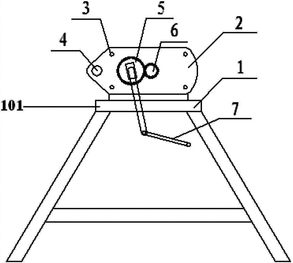
Fig. 1 is the front view of the disclosed transformer high-voltage bushing lead-in wire of the utility model draw-gear;
Fig. 2 is the front view partial enlarged drawing of the disclosed transformer high-voltage bushing lead-in wire of the utility model draw-gear;
Fig. 3 is the rearview of the disclosed transformer high-voltage bushing lead-in wire of the utility model draw-gear;
Fig. 4 is the rearview partial enlarged drawing of the disclosed transformer high-voltage bushing lead-in wire of the utility model draw-gear;
Fig. 5 is the vertical view of the disclosed transformer high-voltage bushing lead-in wire of the utility model draw-gear;
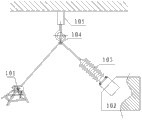
Fig. 6 is the scene use figure of the disclosed transformer high-voltage bushing lead-in wire of the utility model draw-gear.
Among the figure: the 1-pedestal; The 2-fixed head; The 3-connecting axle; The 4-fixing hole; The 5-gear wheel; The 6-pinion; The 7-rocking arm; The 8-braked wheel; The 9-brake bar; 10-steel wire rope capstan winch; The 11-stop-nut; 101-transformer high-voltage bushing lead-in wire draw-gear; The 102-transformer; The 103-bushing; The 104-fixed pulley; 105-overhead traveling crane or crane.
Embodiment
Be elaborated below in conjunction with the structure of the drawings and specific embodiments to transformer high-voltage bushing lead-in wire draw-gear of the present utility model.
A kind of transformer high-voltage bushing lead-in wire draw-gear 101 is comprised of analog bracket, drive transmission and braking stopping means; Described analog bracket comprises pedestal 1, fixed head 2 and connecting axle 3, described fixed head 2 is fixed on the described pedestal 1, described fixed head 2 has two and be fixedly connected with by connecting axle 3 between the two, described fixed head 2 one ends are provided with fixing hole 4, be used for being connected with external equipment, prevent the in use stressed rear movement of transformer high-voltage bushing lead-in wire draw-gear 101; Described drive transmission comprises gear train, rocking arm 7 and steel wire rope capstan winch 10, drives described gear train by described rocking arm 7 and rotates, and then drive described steel wire rope capstan winch 10 rotations; Described braking stopping means comprises braked wheel 8, brake bar 9 and stop-nut 11, and described braked wheel 8 rotates synchronously with described steel wire rope capstan winch 10, and described brake bar 9 is installed on the described fixed head 2 by described stop-nut 11.
For the ease of blocking braked wheel 8 with brake bar 9, be formed with the sawtooth that can be meshed with the tooth on the braked wheel 8 in the end of brake bar 9.
Described gear train comprises a gear wheel 5 and a pinion 6, and described rocking arm 7 is fixed on the described gear wheel 5 and drives described gear wheel 5 and rotates, and described gear wheel 5 drives described pinion 6 and rotates described pinion 6 and described steel wire rope capstan winch 10 coaxial installations.
Described analog bracket is welded by the angle bar of 45mm, mainly plays fixing and supporting role as towing bracket.
As shown in Figure 6, the course of work of the present utility model is:
With the bolt spinning of lifting rope one end on the copper rod of high-voltage connection, then the other end of lifting rope is passed first the middle cavity of transformer 102 bushings 103, through the fixed pulley 104 of overhead traveling crane or the setting of crane 105 hoisting point positions, be fixed at last on the steel wire rope capstan winch 10 of transformer high-voltage bushing lead-in wire draw-gear 101 again; Rotate rocking arm 7 and drive gear wheel 5 rotations, gear wheel 5 rotation driving pinions 6 rotate, and steel wire rope capstan winch 10 rotates synchronously with pinion 6; The pulling lifting rope just can make high-voltage connection pass successively bushing 103 and fixed pulley 104 is wound on the steel wire rope capstan winch 10.After bushing 105 is adjusted to correct position, block braked wheel 8 with an end of brake bar 9, tighten stop-nut 11 and finish braking.After the bushing installation, rotate rocking arm 7 high-voltage connection that is fixed on bushing 103 pedestals is drawn through bushing 103.
This transformer high-voltage bushing lead-in wire draw-gear has adopted overall structure, has convenient transportation, the advantage such as simple in structure, easy for installation, not fragile.Only need during use that this device is shifted to an earlier date the good direction of fixed adjustment and get final product, simple to operation, time saving and energy saving, be suitable for the use of complex working conditions.Pull the lead-in wire angle during use and change along with the variation of sleeve angle, make the position of outlet and sleeve pipe relative fixing, thereby avoided the problem of damage sleeve pipe lead-in wire in the sleeve pipe installation process.Reduce to greatest extent operating personnel's labour intensity, improved operating efficiency, set-up time of single sleeve pipe has been shortened to 15 minutes by original 30 minutes, and greatly reduced workmen's input, improved the fail safe of construction.