CN203197704U - Stone profile grinder - Google Patents
Stone profile grinder Download PDFInfo
- Publication number
- CN203197704U CN203197704U CN 201320203870 CN201320203870U CN203197704U CN 203197704 U CN203197704 U CN 203197704U CN 201320203870 CN201320203870 CN 201320203870 CN 201320203870 U CN201320203870 U CN 201320203870U CN 203197704 U CN203197704 U CN 203197704U
- Authority
- CN
- China
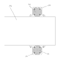
- Prior art keywords
- grinding
- assembly
- grinding spindle
- stone material
- bistrique
- Prior art date
- Legal status (The legal status is an assumption and is not a legal conclusion. Google has not performed a legal analysis and makes no representation as to the accuracy of the status listed.)
- Expired - Lifetime
Links
- 239000004575 stone Substances 0.000 title claims abstract description 31
- 230000005540 biological transmission Effects 0.000 claims abstract description 29
- 239000000700 radioactive tracer Substances 0.000 claims description 48
- 239000000463 material Substances 0.000 claims description 21
- 238000003780 insertion Methods 0.000 claims description 3
- 230000037431 insertion Effects 0.000 claims description 3
- 238000005498 polishing Methods 0.000 abstract description 10
- 230000033001 locomotion Effects 0.000 description 15
- 230000007246 mechanism Effects 0.000 description 14
- 229910001651 emery Inorganic materials 0.000 description 12
- 238000000034 method Methods 0.000 description 12
- 230000008569 process Effects 0.000 description 12
- 230000001360 synchronised effect Effects 0.000 description 10
- 230000001276 controlling effect Effects 0.000 description 5
- 230000008901 benefit Effects 0.000 description 4
- 230000008859 change Effects 0.000 description 4
- 230000000694 effects Effects 0.000 description 4
- 230000000712 assembly Effects 0.000 description 3
- 238000000429 assembly Methods 0.000 description 3
- 238000005516 engineering process Methods 0.000 description 3
- 239000012467 final product Substances 0.000 description 2
- 230000001105 regulatory effect Effects 0.000 description 2
- 238000005096 rolling process Methods 0.000 description 2
- 230000009471 action Effects 0.000 description 1
- 238000006243 chemical reaction Methods 0.000 description 1
- 230000008878 coupling Effects 0.000 description 1
- 238000010168 coupling process Methods 0.000 description 1
- 238000005859 coupling reaction Methods 0.000 description 1
- 230000002950 deficient Effects 0.000 description 1
- 238000013467 fragmentation Methods 0.000 description 1
- 238000006062 fragmentation reaction Methods 0.000 description 1
- 238000003754 machining Methods 0.000 description 1
- 230000005693 optoelectronics Effects 0.000 description 1
- 238000007517 polishing process Methods 0.000 description 1
Images






Landscapes
- Grinding Of Cylindrical And Plane Surfaces (AREA)
Abstract
The utility model provides a stone profile grinder. A profile grinding device comprises a lifting device, a grinding head spindle box transmission device and a grinding assembly. The lifting device is composed of an air cylinder body, a cylinder rod and a lifting plate, wherein the lifting plate is fixedly connected with the air cylinder body, the upper end of the cylinder rod is inserted into the air cylinder body, and the lower end of the cylinder rod is fixedly connected with a transverse shift assembly. The grinding head spindle box transmission device is composed of an upper swing shaft, a grinding head spindle box, a profile head and a plurality of guide columns, wherein the upper swing shaft is installed above the lifting plate in a rotary mode, the lifting plate is fixedly connected with the grinding head spindle box through the guide columns, the grinding head spindle box is connected with the grinding assembly in a transmission mode, the profile head is sleeved at one end of the upper swing shaft in a fastened mode. The stone profile grinder is flexible in transmission, can be used for carrying out polishing on the surfaces of stone workpieces with various shapes, and is high in polishing precision and wide in range of application.
Description
Technical field
The utility model belongs to the stone machining equipment field, especially a kind of can be used for carrying out the stone material shape imitation mill of rubbing down on the various shape stone material surface of the works.
Background technology
The mode of polishing for nonplanar shaped stone material in early days generally adopts manual polishing or polishes with hand steered grinding machine, this mode equipment investment is few, mainly dependence manually realizes, labour intensity is large, productivity ratio is low, cost is high, precision is controlled the defectives such as difficulty, difficult quality guarantee and noise pollution are serious so have.Application publication number is that the Chinese patent of CN102941520 A has been announced a kind of type stone profiling machine with polishing function, comprises a crossbeam, two longerons, a Mobile base, a crane, profiling control device and work holder; The first travel mechanism is housed between crossbeam and the longeron, the second travel mechanism is housed between Mobile base and the crossbeam, the 3rd travel mechanism is housed between crane and the Mobile base, this type stone profiling machine also comprises the sanding apparatus that is arranged on the crane, this sanding apparatus comprises the mount pad that is arranged on the crane, can be arranged at up or down the axle box on the mount pad, be arranged vertically the countershaft on axle box, be arranged to connect on the axle box and drive the first motor that countershaft rotates, be arranged at and drive the executing agency that axle box moves up and down between mount pad and the axle box, the countershaft lower end is equipped with emery wheel.When the processing circular stone pillar, follow the trail of the stencil master curved surface by optoelectronic director head, then curved surface signal is sent to the PLC Programmable Logic Controller, the PLC Programmable Logic Controller is controlled second, third travel mechanism and main motor action according to curved surface signal, and the control work holder drives the stone column rotation, make saw blade carry out lifting and traversing according to the template curved surface, just can process the cylinder consistent with stencil master, control again the turning motor driving saw blade is avoided, adopt sanding apparatus that the outer surface of cylindrical stone column is polished.Although the sanding apparatus of this invention can be polished to the outer circumference surface of workpiece, but, still there is shortcomings in this device: (1) this device is specifically designed to the relatively large cylindrical or conical stone material of processing, that rotation by workpiece realizes the cylindrical polishing of workpiece, and for through the shaped stone material after the profiling, the sanding apparatus of this device can't polish its erose surface; (2) the utility model adopts the outer circumference surface of emery wheel that stone material is polished, effective contact area of emery wheel and workpiece is little, the brightness of emery wheel polishing is relatively poor, add emery wheel and be generally rigid attachment with connecting of mainshaft mechanism, the vibration that produces in the grinding process easily causes the surperficial unbalance stress of workpiece, the precision of polishing is all relatively poor, is not suitable for meticulous polishing; (3) because emery wheel is generally rigid attachment with connecting of mainshaft mechanism, in the polishing process, easily cause the fragmentation of emery wheel, potential safety hazard is very big.Granted publication number has been announced a kind of planet profiling grinding head for polishing for the Chinese patent of CN 201105406Y, comprise grinding head body, driving gear set is housed in grinding head body, in axial sliding output shaft is housed in bistrique, be provided with travelling gear at output shaft and bite mutually the driven gear that closes, at the output of output shaft the unsteady emery wheel that can swing around axle head is housed by elastic coupling joint.Because the emery wheel of this device floats, the certain angle that can tilt is fitted the end face of emery wheel all the time with the rough surface of workpiece, and still, this bistrique can't carry out profiling in the rubbing down process, and the rubbing down precision is low.
Summary of the invention
The utility model provides a kind of and can be used for carrying out the stone material shape imitation mill of rubbing down on the various shape stone material surface of the works.
The technical solution of the utility model is: a kind of stone material shape imitation mill, comprise frame, indulge away assembly, crossbeam, traversing assembly, the profiling mill apparatus, the gauge finder clamping device, workpiece support device and PLC intelligence control system, indulge away assembly and comprise two sections of indulging away that are separately positioned on the frame of the left and right sides, beam erection is between two sections of indulging away, traversing assembly is slidingly mounted on the crossbeam, the profiling mill apparatus comprises lowering or hoisting gear, grinding spindle case transmission device and grinding assembly, lowering or hoisting gear is by cylinder block, cylinder bar and lifter plate form, lifter plate is fixedly connected with cylinder block, the upper end of cylinder bar is plugged in the cylinder block, the lower end is fixedly connected with traversing assembly, and grinding spindle case transmission device is by upper swinging axle, the grinding spindle case, tracer head and some guide pillars form; Upper swinging axle is rotatably installed in the lifter plate top, lifter plate is fixedly connected with the grinding spindle case by guide pillar, the grinding spindle case is in transmission connection with the grinding assembly again, the bottom of grinding assembly arranges bistrique, workpiece support device is arranged on the below of bistrique, the tracer head adapter sleeve is located at swinging axle one end, the gauge finder clamping device is arranged on the below of tracer head, the PLC intelligence control system is located at indulges away the arbitrary outside of assembly, lowering or hoisting gear, traversing assembly, indulges away assembly and grinding assembly and all is connected with the PLC intelligent control system circuit.
Operation principle of the present utility model is: at first transversely surface configuration is placed on the tracer head below with the workpiece gauge finder that transversely surface configuration is identical, simultaneously workpiece is placed on the bistrique below; Then controlling traversing assembly by the PLC intelligence control system starts, the moment that traversing assembly starts is followed successively by lowering or hoisting gear, upper swinging axle and tracer head provide the trend power of transverse shifting, when tracer head contacts with the gauge finder upper surface, the acting in conjunction of transverse shifting trend power and gauge finder upper surface shape, be followed successively by tracer head, upper swinging axle is provided at the trend power that swings in a lateral direction, this swing trend power makes swinging axle carry out rotation, the drive tracer head of taking advantage of a situation again swings accordingly, until the upper edge of the lower edge of tracer head and gauge finder is tangent, then, tracer head produces under the acting in conjunction of transverse shifting trend power and gauge finder upper surface shape along the gauge finder edge trend (being two kinds of trend of lifting and transverse shifting) of sliding transversely, thereby promote whole profiling mill apparatus and do lifting and transverse shifting, do corresponding lifting and transverse shifting by grinding spindle case drive grinding assembly and bistrique again, the utility model is being carried out in the rubbing down process workpiece surface, and bistrique is identical at the transversely surperficial movement locus of gauge finder along workpiece transversely surperficial movement locus and tracer head.Simultaneously, the PLC intelligence control system is indulged away part by control grinding assembly and two respectively and is realized the rotation of bistrique and vertically moving of whole profiling mill apparatus.
The utility model has the advantage of: (1) is in grinding process, tracer head of the present utility model can swing, and the swing trend of tracer head is mainly determined by the shape of gauge finder upper edge, and, only have when tracer head and be rocked to its lower edge and gauge finder upper edge when tangent, tracer head could be along table on the gauge finder along sliding, the motion change of tracer head is more flexible, the profiling so that tracer head can slide along the upper edge of various shapes, therefore, the utility model is applicable to the rubbing down on various special-shaped workpieces surface; (2) grinding spindle case transmission device of the present utility model is frame for movement, compares with electric control of the prior art, and transmission is more reliable; (3) gauge finder carries out profiling to surface of the work, the high conformity of workpiece rubbing down, steady quality; (4) gauge finder is structure independently, can change easily according to need gauge finder; (5) profiling mill apparatus of the present utility model can move according to the shape of gauge finder upper edge, and therefore, workpiece only need be fixed and get final product, and is lower to the clamping device requirement of workpiece.
Rotate on the grinding spindle case and wear swing pipe, lower swing Guan Yiduan by synchronous drive mechanism be connected with upper swinging axle, the other end is fixedly connected with the grinding assembly.Such design, can make the oscillating motion of tracer head successively by upper swinging axle, synchronous drive mechanism, lower swing pipe, grinding assembly, so that the bistrique of grinding assembly bottom swings accordingly, such design can make the grinding face of bistrique and the upper surface of workpiece remain tangent, has greatly improved the rubbing down precision.
The four-bar linkage structure that synchronous drive mechanism is served as reasons upper oscillating deck, lower swing plate and formed with upper oscillating deck and hinged two guide rods of lower swing plate respectively, wherein, upper oscillating deck is fixedly connected with the end of upper swinging axle, and the lower swing plate is fixedly connected with the end of lower swing pipe.The structure of this synchronous drive mechanism is four-bar linkage structure, and transmission is more flexible, and synchronism is high.
In specific implementation process, the left and right sides of tracer head protrudes from the tracer head plane one guide wheel is set respectively, and gauge finder is arranged on the below of guide wheel.Compare the slip of tracer head on the gauge finder upper edge, adopt guide wheel to roll tracer head not easy to wear and guide wheel in the gauge finder upper edge.
Traversing assembly is comprised of sliding sash, tooth bar, sideslip gear, reductor and traversing drive motors, and sliding sash slides and is fastened on outside the crossbeam, and traversing drive motors and reductor are fixedly installed on the top of sliding sash, and the sideslip gear adapter sleeve is located on the output shaft of reductor.Under the effect of traversing drive motors, traversing assembly can be along cross beam movement.
Sliding sash sets firmly several guide pillar seats outward, and each guide pillar slides through a guide pillar seat, is fixedly connected with the grinding spindle case.Such design can make the outer surface of the relative sliding sash of guide pillar slide up and down, and can realize the free lifting of guide pillar, the stability in the time of can improving again whole profiling mill apparatus lifting.
Several traversing assemblies of space set on the described crossbeam, be fixedly connected with by connecting rod between the adjacent traversing assembly, one profiling mill apparatus is installed on each traversing assembly, wherein, at least one traversing assembly is comprised of sliding sash, tooth bar, sideslip gear, reductor and traversing drive motors, and remaining traversing assembly all only is comprised of sliding sash.Such design can be increased work efficiency by the quantity that increases the profiling mill apparatus, can guarantee again the uniformity of different profiling mill apparatus motions.
The gauge finder clamping device by the corners such as base, T shape bracing frame and two just seat form, T shape bracing frame is fixed on the base top, the corners such as two just have been fixed on T shape bracing frame top in a seat left-right symmetry interval, two wait the corner just between the seat for the insertion of gauge finder lower edge.In specific implementation process, the gauge finder clamping device can further improve: wait between the firm seat in corner and the gauge finder to be bolted.
The profiling mill apparatus comprises that also one is specifically designed to the workpiece support device of arc plate, and workpiece support device is comprised of workpiece holder and two stay pipes, and the stay pipe interval is fixedly installed on the bracing frame.During work, the arc plate workpiece is as long as interior arc generatrix is parallel with stay pipe and centering is positioned on the stay pipe, and this workpiece support device is simple in structure, and cost is low.
The grinding assembly is comprised of grinding spindle and bistrique main-gear box, and bistrique comprises abrasive disk seat and several mills, and the abrasive disk seat adapter sleeve is located at the lower end of grinding spindle, and mill is arranged on the bottom of abrasive disk seat.Polish with the outer circumference surface by emery wheel in the prior art and to compare, the utility model adopts the end face of mill that workpiece is polished, and effectively the Grinding Contact face is larger, and rubbing down brightness is higher.
Grinding spindle is connected with grinding motor, concrete syndeton is: grinding spindle tightens sheathed bistrique main-gear box, the bistrique main-gear box is fixedly connected with the lower swing pipe, the center rotating of lower swing pipe wears a mandrel, mandrel one end and grinding motor is in transmission connection, the other end stretches in the bistrique main-gear box, the bistrique main-gear box contains two circular hole bevel gears that are set in respectively on grinding spindle and the mandrel, be meshed between the two circular hole bevel gears, between mandrel and the bistrique main-gear box for being rotationally connected.Like this, can realize that grinding motor drives the grinding spindle transmission, reasonable in design because mandrel is located in the center of lower swing pipe simultaneously, conserve space.Further improve and be: for being rotationally connected, like this, the rotation of grinding spindle and swing can not interfere with each other, carry out simultaneously between mandrel and the bistrique main-gear box.
Grinding motor is arranged on the top of lifter plate.Grinding motor is synchronized with the movement with whole profiling mill apparatus, guarantee the transmission stability of grinding motor, and grinding motor can not swing with grinding spindle, stability when avoiding the effect of weight grinding spindle of grinding motor to swing, thus grinding accuracy improved.
Realize transmission by belt between the output shaft of grinding motor and the mandrel.Directly compare by the gear drive grinding spindle with grinding motor of the prior art, the vibration of grinding spindle is less.
Several adjustable support bars vertically are set on the lifter plate, and grinding motor is installed in the top of adjustable support bar.Such design can be regulated by adjustable support bar the height of grinding motor, all forms tight fit so that belt can and be installed in the belt pulley on the grinding motor output shaft and is installed between the driven pulley on the mandrel.
The top of grinding spindle is provided for controlling the Pneumatic controller of grinding spindle lifting, and Pneumatic controller is connected with the PLC intelligent control system circuit.Make grinding spindle in cylinder stroke by the air pressure supply system, the grinding face of mill is contacted with the workpiece grinding face all the time, and keep setting grinding force, simultaneously, mill contacts for " soft " with workpiece, and safety coefficient is high.
The physical arrangement of indulging away part, PLC intelligence controlling device, air pressure control section, bistrique and mill in the utility model is known technology, does not do at this and gives unnecessary details.
Between upper swinging axle of the present utility model and the lifter plate, between lower swing pipe and the grinding spindle case and be rolling pair between lower swing pipe and the mandrel, perhaps realize being rotatably connected by bearing.
Description of drawings
Fig. 1 is the structural representation under the profiling mill apparatus duty of the present utility model, and dotted line is the circular arc upper edge outline line of gauge finder;
Fig. 2 is the front view of profiling mill apparatus of the present utility model;
Fig. 3 is the side view of profiling mill apparatus of the present utility model, and wherein, crossbeam is cutaway view;
Fig. 4 is the side view of the profiling mill apparatus with guide wheel of the present utility model, and wherein, crossbeam is cutaway view;
Fig. 5 is the rearview of profiling mill apparatus of the present utility model;
Fig. 6 is the cutaway view of profiling mill apparatus of the present utility model;
Fig. 7 is the top view of horizontal frame of the present utility model, guide pillar and guide pillar seat.
The specific embodiment
Now specifically set forth by reference to the accompanying drawings embodiment of the present utility model:
In conjunction with Fig. 1 ~ 3, a kind of stone material shape imitation mill, comprise frame 1, indulge away assembly 18, crossbeam 7, traversing assembly 3, profiling mill apparatus 4, gauge finder clamping device 35, workpiece support device 41 and PLC intelligence control system 5, indulge away assembly 18 and comprise two sections of indulging away 2 that are separately positioned on the left and right sides frame 1, crossbeam 7 is erected between two sections of indulging away 2, traversing assembly 3 is slidingly mounted on the crossbeam 7, profiling mill apparatus 4 comprises lowering or hoisting gear 8, grinding spindle case transmission device 10 and grinding assembly 9, lowering or hoisting gear 8 is by cylinder block 47, cylinder bar 46 and lifter plate 15 form, lifter plate 15 is fixedly connected with cylinder block 47, the upper end of cylinder bar 46 is plugged in the cylinder block 47, the lower end is fixedly connected with traversing assembly 3, in the course of the work, cylinder bar 46 can move up and down in cylinder block 47 under external force, and grinding spindle case transmission device 10 is by upper swinging axle 12, grinding spindle case 13, tracer head 6 and some guide pillars 16 form; Upper swinging axle 12 is rotatably installed in lifter plate 15 tops, lifter plate 15 is fixedly connected with grinding spindle case 13 by guide pillar 16, grinding spindle case 13 is in transmission connection with grinding assembly 9 again, the bottom of grinding assembly 9 arranges bistrique 52, workpiece support device 41 is arranged on the below of bistrique 52, tracer head 6 adapter sleeves are located at swinging axle 12 1 ends, tracer head clamping device 35 is arranged on the below of tracer head 6, PLC intelligence control system 5 is located at indulges away assembly 18 arbitrary outsides,, lowering or hoisting gear 8, traversing assembly 3, indulging away assembly 2 is connected with the grinding assembly and all is connected with PLC intelligence control system 5 circuit.
Operation principle of the present utility model is: at first transversely surface configuration is placed on tracer head 6 belows with workpiece 22 gauge finder 21 that transversely surface configuration is identical, simultaneously workpiece 22 is placed on bistrique 52 belows; Then start by the traversing assembly 3 of PLC intelligence control system 5 controls, the moment that traversing assembly 3 starts is followed successively by lowering or hoisting gear 8, upper swinging axle 12 and tracer head 6 provide the trend power of transverse shifting, when tracer head 6 contacts with gauge finder 21 upper surfaces, the acting in conjunction of transverse shifting trend power and gauge finder 21 upper surface shapes, be followed successively by tracer head 6, upper swinging axle 12 is provided at the trend power that swings in a lateral direction, this swing trend power makes swinging axle 12 carry out rotation, the drive tracer head 6 of taking advantage of a situation again swings accordingly, until the upper edge of the lower edge of tracer head 6 and gauge finder 21 is tangent, then, tracer head 6 produces under the acting in conjunction of transverse shifting trend power and gauge finder 21 upper surface shapes along the gauge finder 21 edge trend (being two kinds of trend of lifting and transverse shifting) of sliding transversely, thereby promote whole profiling mill apparatus 4 and do lifting and transverse shifting, do corresponding lifting and transverse shifting by grinding spindle case 13 drive grinding assemblies 9 and bistrique 52 again, the utility model is being carried out in the rubbing down process workpiece 22 upper surfaces, and bistrique 52 is identical at the transversely surperficial movement locus of gauge finder 21 along workpiece 22 transversely surperficial movement locus and tracer head 6.Simultaneously, PLC intelligence control system 5 is indulged away part 2 by control grinding assembly 9 and two respectively and is realized the rotation of bistrique 52 and vertically moving of whole profiling mill apparatus 4.
The utility model has the advantage of: (1) is in grinding process, tracer head 6 of the present utility model can swing, and the swing trend of tracer head 6 is mainly determined by the shape of gauge finder 21 upper edges, and, only have when tracer head 6 and be rocked to its lower edge and gauge finder 21 upper edges when tangent, tracer head 6 could be along table on the gauge finder 21 along sliding, the motion change of tracer head is more flexible, the profiling so that tracer head 6 can slide along the upper edge of various shapes, therefore, the utility model is applicable to the rubbing down on various special-shaped workpieces surface; (2) grinding spindle case transmission device of the present utility model is frame for movement, compares with electric control of the prior art, and transmission is more reliable; (3) profiling is carried out, the high conformity of workpiece 22 rubbing downs, steady quality in 21 pairs of workpiece 22 surfaces of gauge finder; (4) gauge finder 21 is structures independently, can change easily according to need gauge finder 21; (5) profiling mill apparatus 4 of the present utility model can move according to the shape of gauge finder 21 upper edges, and therefore, workpiece only need be fixed and get final product, and is lower to the clamping device requirement of workpiece 22.
As shown in Figure 6, rotate on the grinding spindle case 13 and wear swing pipe 14, lower swing pipe 14 1 ends by synchronous drive mechanism 11 be connected with upper swinging axle 12, the other end is fixedly connected with grinding assembly 9.Such design, can make the oscillating motion of tracer head 6 successively by upper swinging axle 12, synchronous drive mechanism 11, lower swing pipe 14, grinding assembly 9, so that the bistrique 52 of grinding assembly bottom swings accordingly, such design can make the grinding face of bistrique 52 and the upper surface of workpiece 22 remain tangent, has greatly improved the rubbing down precision.
As shown in Figure 5, the four-bar linkage structure that synchronous drive mechanism 11 is served as reasons upper oscillating deck 23, lower swing plate 24 and formed with upper oscillating deck 23 and lower swing plate 24 hinged two guide rods 25 respectively, wherein, upper oscillating deck 23 is fixedly connected with the end of upper swinging axle 12, and lower swing plate 24 is fixedly connected with the end of lower swing pipe 14.The structure of this synchronous drive mechanism 11 is four-bar linkage structure, and transmission is more flexible, and synchronism is high.
In specific implementation process, the left and right sides of tracer head 6 protrudes from tracer head 6 planes one guide wheel 19 is set respectively, and gauge finder 21 is arranged on the below (in conjunction with Fig. 2, Fig. 4) of guide wheel 19.Compare the slip of tracer head 6 on gauge finder 21 upper edges, adopt guide wheel 19 to roll tracer head 6 not easy to wear and guide wheel 19 in gauge finder 21 upper edges.
As shown in Figure 3, traversing assembly 3 is comprised of sliding sash 26, tooth bar 28, sideslip gear 29, reductor 56 and traversing drive motors 30, sliding sash 26 slides and is fastened on outside the crossbeam 7, traversing drive motors 30 and reductor 56 are fixedly installed on the top of sliding sash 26, and sideslip gear 29 adapter sleeves are located on the output shaft of reductor 56.Under the effect of traversing drive motors 30, traversing assembly 3 can move along crossbeam 7.
As shown in Figure 3, set firmly several guide pillar seats 34 outside the sliding sash 26, each guide pillar 16 slides through a guide pillar seat 34, is fixedly connected with grinding spindle case 13.Such design can make the outer surface of guide pillar 16 relative sliding sashes 26 slide up and down, and can realize the free lifting of guide pillar 16, the stability in the time of can improving again whole profiling mill apparatus 4 lifting.
As shown in Figure 1, several traversing assemblies 3 of space set on the described crossbeam 7, be fixedly connected with by connecting rod 32 between the adjacent traversing assembly 3, one profiling mill apparatus 4 is installed on each traversing assembly 3, wherein, at least one traversing assembly 3 is comprised of sliding sash 26, tooth bar 28, sideslip gear 29, reductor 56 and traversing drive motors 30, and remaining traversing assembly 3 ' all only is comprised of sliding sash 26.Such design can be increased work efficiency by the quantity that increases profiling mill apparatus 4, can guarantee again the uniformity of different profiling mill apparatus 4 motions.
As shown in Figure 4, gauge finder clamping device 35 by the corners such as base 36, T shape bracing frame 37 and two just seat 38 form, T shape bracing frame 37 is fixed on base 36 tops, the corners such as two just have been fixed on T shape bracing frame 37 tops in seat 38 left-right symmetry intervals, two wait the corner just between the seat 7 for the insertion of gauge finder 21 lower edges.In specific implementation process, gauge finder clamping device 35 can further improve: wait between the firm seat 38 in corner and the gauge finder 21 by bolt 39 fixing (as shown in Figure 4).
As shown in Figure 2, profiling mill apparatus 4 comprises that also one is specifically designed to the workpiece support device 41 of arc plate, and workpiece support device 41 is comprised of workpiece holder 42 and two stay pipes 43, and stay pipe 43 intervals are fixedly installed on the bracing frame 42.During work, arc plate workpiece 22 if in the parallel and centering of arc generatrix 20 and stay pipe 43 be positioned on the stay pipe 43, this workpiece support device 41 is simple in structure, cost is low.
As shown in Figure 6, grinding assembly 9 is comprised of grinding spindle 50 and bistrique main-gear box 51, and bistrique 52 comprises abrasive disk seat 31 and several mills 17, and abrasive disk seat 31 adapter sleeves are located at the lower end of grinding spindle 50, and mill 17 is arranged on the bottom of abrasive disk seat 31.Polish with the outer circumference surface by emery wheel in the prior art and to compare, the utility model adopts the end face of mill 17 that workpiece is polished, and effectively the Grinding Contact face is larger, and rubbing down brightness is higher.
As shown in Figure 6, grinding spindle 50 is connected with grinding motor 53, concrete syndeton is: grinding spindle 50 tightens sheathed bistrique main-gear box 51, bistrique main-gear box 51 is fixedly connected with lower swing pipe 14, the center rotating of lower swing pipe 14 wears a mandrel 54, mandrel 54 1 ends and grinding motor 53 are in transmission connection, the other end stretches in the bistrique main-gear box 51, bistrique main-gear box 51 contains between two circular hole bevel gear 55, two circular hole bevel gears 55 that are set in respectively on grinding spindle 50 and the mandrel 54 and is meshed.Like this, can realize that grinding motor 53 drives grinding spindle 50 transmissions, reasonable in design because mandrel 54 is located in the center of lower swing pipe 14 simultaneously, conserve space.Further improve and be: for being rotationally connected, like this, rotation and the swing of grinding spindle 50 do not interfere with each other, carries out simultaneously between mandrel 54 and the bistrique main-gear box 51.
As shown in Figure 6, grinding motor 53 is arranged on the top of lifter plate 15, grinding motor 53 is synchronized with the movement with whole profiling mill apparatus 4, guarantee the transmission stability of grinding motor 53, and, grinding motor 53 can not swing with grinding spindle 50, the stability when avoiding the effect of weight grinding spindle 50 of grinding motor 50 to swing, thus improve grinding accuracy.
Realize transmission by belt 57 between the output shaft of grinding motor 53 and the mandrel 54.Directly compare by gear drive grinding spindle 50 with grinding motor 53 of the prior art, the vibration of grinding spindle 50 is less.
As shown in Figure 6, several adjustable support bars 59 are set vertically on the lifter plate 15, grinding motor 53 is installed in the top of adjustable support bar 59.Such design can be regulated by adjustable support bar 59 height of grinding motor 53, all forms tight fit so that belt 57 can and be installed in the belt pulley on grinding motor 53 output shafts and is installed between the driven pulley on the mandrel 54.
As shown in Figure 1, the top of grinding spindle 50 is provided for controlling the Pneumatic controller 58 of grinding spindle 50 liftings, and Pneumatic controller 58 is connected with PLC intelligence control system 5 circuit.Make grinding spindle 50 in cylinder stroke by air pressure supply system 58, the grinding face of mill 17 is contacted with the workpiece grinding face all the time, and keep setting grinding force, simultaneously, mill 17 contacts for " soft " with workpiece, and safety coefficient is high.
The physical arrangement of indulging away part 2, PLC intelligence controlling device 5, air pressure control section 58, bistrique 52 and mill 17 in the utility model is known technology, does not do at this and gives unnecessary details.
Between the upper swinging axle 12 and lifter plate 15 in the utility model, between lower swing pipe 14 and the grinding spindle case 13 and be rolling pair between lower swing pipe 14 and the mandrel 54, perhaps realize being rotatably connected by bearing.
The above only is the utility model preferred embodiment; be not so limit claim of the present utility model; every equivalent structure or equivalent flow process conversion that utilizes the utility model specification and accompanying drawing content to do; or directly or indirectly be used in other relevant technical fields, all in like manner be included in the scope of patent protection of the present utility model.
Claims (10)
1. a stone material shape imitation grinds, comprise frame, indulge away assembly, crossbeam, traversing assembly, the profiling mill apparatus, the profile fastener device, workpiece support device and PLC intelligence control system, indulge away assembly and comprise two sections of indulging away that are separately positioned on the frame of the left and right sides, beam erection is between two sections of indulging away, traversing assembly is slidingly mounted on the crossbeam, it is characterized in that: the profiling mill apparatus comprises lowering or hoisting gear, grinding spindle case transmission device and grinding assembly, lowering or hoisting gear is by cylinder block, cylinder bar and lifter plate form, lifter plate is fixedly connected with cylinder block, the upper end of cylinder bar is plugged in the cylinder block, the lower end is fixedly connected with traversing assembly, and grinding spindle case transmission device is by upper swinging axle, the grinding spindle case, tracer head and some guide pillars form; Upper swinging axle is rotatably installed in the lifter plate top, lifter plate is fixedly connected with the grinding spindle case by guide pillar, the grinding spindle case is in transmission connection with the grinding assembly again, the bottom of grinding assembly arranges bistrique, workpiece support device is arranged on the below of bistrique, the tracer head adapter sleeve is located at swinging axle one end, the gauge finder clamping device is arranged on the below of tracer head, the PLC intelligence control system is located at indulges away the arbitrary outside of assembly, lowering or hoisting gear, traversing assembly, indulges away assembly and grinding assembly and all is connected with the PLC intelligent control system circuit.
2. a kind of stone material shape imitation according to claim 1 grinds, it is characterized in that: traversing assembly is comprised of sliding sash, tooth bar, sideslip gear, reductor and traversing drive motors, sliding sash slides and is fastened on outside the crossbeam, traversing drive motors and reductor are fixedly installed on the top of sliding sash, and the sideslip gear adapter sleeve is located on the output shaft of reductor.
3. a kind of stone material shape imitation according to claim 1 grinds, it is characterized in that: the gauge finder clamping device by the corners such as base, T shape bracing frame and two just seat form, T shape bracing frame is fixed on the base top, the corners such as two just have been fixed on T shape bracing frame top in a seat left-right symmetry interval, two wait the corner just between the seat for the insertion of gauge finder lower edge.
4. a kind of stone material shape imitation mill according to claim 3 is characterized in that: wait between the firm seat in corner and the gauge finder to be bolted.
5. a kind of stone material shape imitation according to claim 1 grinds, it is characterized in that: the profiling mill apparatus comprises that also one is specifically designed to the workpiece support device of arc plate, workpiece support device is comprised of workpiece holder and two stay pipes, and the stay pipe interval is fixedly installed on the bracing frame.
6. a kind of stone material shape imitation according to claim 1 grinds, it is characterized in that: the grinding assembly is comprised of grinding spindle and bistrique main-gear box, bistrique comprises abrasive disk seat and several mills, and the abrasive disk seat adapter sleeve is located at the lower end of grinding spindle, and mill is arranged on the bottom of abrasive disk seat.
7. a kind of stone material shape imitation according to claim 6 grinds, it is characterized in that: grinding spindle is connected with grinding motor, concrete syndeton is: grinding spindle tightens sheathed bistrique main-gear box, the bistrique main-gear box is fixedly connected with the lower swing pipe, the center rotating of lower swing pipe wears a mandrel, mandrel one end and grinding motor is in transmission connection, the other end stretches in the bistrique main-gear box, the bistrique main-gear box contains two circular hole bevel gears that are set in respectively on grinding spindle and the mandrel, is meshed between the two circular hole bevel gears.
8. a kind of stone material shape imitation mill according to claim 7 is characterized in that: realize transmission by belt between the output shaft of grinding motor and the mandrel.
9. a kind of stone material shape imitation according to claim 8 grinds, and it is characterized in that: several adjustable support bars vertically are set on the lifter plate, and grinding motor is installed in the top of adjustable support bar.
10. a kind of stone material shape imitation according to claim 1 grinds, and it is characterized in that: the top of grinding spindle is provided for controlling the Pneumatic controller of grinding spindle lifting, and Pneumatic controller is connected with the PLC intelligent control system circuit.
Priority Applications (1)
| Application Number | Priority Date | Filing Date | Title |
|---|---|---|---|
| CN 201320203870 CN203197704U (en) | 2013-04-22 | 2013-04-22 | Stone profile grinder |
Applications Claiming Priority (1)
| Application Number | Priority Date | Filing Date | Title |
|---|---|---|---|
| CN 201320203870 CN203197704U (en) | 2013-04-22 | 2013-04-22 | Stone profile grinder |
Publications (1)
| Publication Number | Publication Date |
|---|---|
| CN203197704U true CN203197704U (en) | 2013-09-18 |
Family
ID=49141843
Family Applications (1)
| Application Number | Title | Priority Date | Filing Date |
|---|---|---|---|
| CN 201320203870 Expired - Lifetime CN203197704U (en) | 2013-04-22 | 2013-04-22 | Stone profile grinder |
Country Status (1)
| Country | Link |
|---|---|
| CN (1) | CN203197704U (en) |
Cited By (13)
| Publication number | Priority date | Publication date | Assignee | Title |
|---|---|---|---|---|
| CN104889836A (en) * | 2015-05-22 | 2015-09-09 | 南通中远船务工程有限公司 | Hole grinding and polishing device and use method thereof |
| CN107471031A (en) * | 2017-10-14 | 2017-12-15 | 毛啸宇 | A kind of cabinet handle deburring device |
| CN107775824A (en) * | 2017-10-09 | 2018-03-09 | 台州石磊工贸有限公司 | A kind of circular arc mo(u)lding machine and its processing method |
| CN108274326A (en) * | 2017-10-14 | 2018-07-13 | 毛啸宇 | A kind of sander grinding head driving mechanism |
| CN108608279A (en) * | 2018-07-19 | 2018-10-02 | 佛山市硕宇机械研发有限公司 | Burnishing device for large scale stone material |
| CN108705420A (en) * | 2018-07-06 | 2018-10-26 | 泉州市贤兴机械制造有限公司 | A kind of profiling polishing equipment |
| CN110026854A (en) * | 2019-05-17 | 2019-07-19 | 雅丽日化实业(惠州)有限公司 | A kind of double-station edge polisher |
| CN110421463A (en) * | 2019-08-01 | 2019-11-08 | 宁波奥涵机械科技有限公司 | A kind of round sand machine grinding head mechanism |
| CN110935921A (en) * | 2019-12-26 | 2020-03-31 | 山西英领智能科技有限公司 | Automatic spherical surface body profiling polishing machine and polishing method |
| CN113231921A (en) * | 2021-04-14 | 2021-08-10 | 成都先进金属材料产业技术研究院股份有限公司 | Metal plate fatigue sample polishing device and method |
| CN113798955A (en) * | 2021-10-11 | 2021-12-17 | 安徽工程大学 | Small curvature free-form surface profiling grinding device and grinding method thereof |
| CN114131463A (en) * | 2021-11-01 | 2022-03-04 | 怀宁县群力汽车配件有限公司 | Polishing tool for processing floating type filter shell |
| CN115741474A (en) * | 2022-12-12 | 2023-03-07 | 广东钶锐锶数控技术股份有限公司 | Automatic polishing equipment for numerical control machine tool shank |
-
2013
- 2013-04-22 CN CN 201320203870 patent/CN203197704U/en not_active Expired - Lifetime
Cited By (19)
| Publication number | Priority date | Publication date | Assignee | Title |
|---|---|---|---|---|
| CN104889836B (en) * | 2015-05-22 | 2018-01-05 | 南通中远船务工程有限公司 | A kind of hole sanding and polishing device and its application method |
| CN104889836A (en) * | 2015-05-22 | 2015-09-09 | 南通中远船务工程有限公司 | Hole grinding and polishing device and use method thereof |
| CN107775824A (en) * | 2017-10-09 | 2018-03-09 | 台州石磊工贸有限公司 | A kind of circular arc mo(u)lding machine and its processing method |
| CN107775824B (en) * | 2017-10-09 | 2024-04-12 | 台州石磊工贸有限公司 | A circular arc line machine and processing method thereof |
| CN107471031A (en) * | 2017-10-14 | 2017-12-15 | 毛啸宇 | A kind of cabinet handle deburring device |
| CN108274326A (en) * | 2017-10-14 | 2018-07-13 | 毛啸宇 | A kind of sander grinding head driving mechanism |
| CN108705420B (en) * | 2018-07-06 | 2024-02-20 | 泉州市贤兴机械制造有限公司 | Profiling polishing equipment |
| CN108705420A (en) * | 2018-07-06 | 2018-10-26 | 泉州市贤兴机械制造有限公司 | A kind of profiling polishing equipment |
| CN108608279A (en) * | 2018-07-19 | 2018-10-02 | 佛山市硕宇机械研发有限公司 | Burnishing device for large scale stone material |
| CN108608279B (en) * | 2018-07-19 | 2025-03-07 | 佛山市硕宇机械研发有限公司 | Polishing device for large-size stones |
| CN110026854A (en) * | 2019-05-17 | 2019-07-19 | 雅丽日化实业(惠州)有限公司 | A kind of double-station edge polisher |
| CN110421463A (en) * | 2019-08-01 | 2019-11-08 | 宁波奥涵机械科技有限公司 | A kind of round sand machine grinding head mechanism |
| CN110935921B (en) * | 2019-12-26 | 2024-04-23 | 山西英领智能科技有限公司 | Automatic profiling polishing machine and polishing method for spherical body |
| CN110935921A (en) * | 2019-12-26 | 2020-03-31 | 山西英领智能科技有限公司 | Automatic spherical surface body profiling polishing machine and polishing method |
| CN113231921A (en) * | 2021-04-14 | 2021-08-10 | 成都先进金属材料产业技术研究院股份有限公司 | Metal plate fatigue sample polishing device and method |
| CN113798955B (en) * | 2021-10-11 | 2022-07-26 | 安徽工程大学 | Small-curvature free-form surface profiling grinding device and grinding method thereof |
| CN113798955A (en) * | 2021-10-11 | 2021-12-17 | 安徽工程大学 | Small curvature free-form surface profiling grinding device and grinding method thereof |
| CN114131463A (en) * | 2021-11-01 | 2022-03-04 | 怀宁县群力汽车配件有限公司 | Polishing tool for processing floating type filter shell |
| CN115741474A (en) * | 2022-12-12 | 2023-03-07 | 广东钶锐锶数控技术股份有限公司 | Automatic polishing equipment for numerical control machine tool shank |
Similar Documents
| Publication | Publication Date | Title |
|---|---|---|
| CN203471499U (en) | Polisher for polishing inner wall and outer wall of pipe | |
| CN205394208U (en) | Grind tile machine | |
| CN206366917U (en) | A kind of surface grinding machine cooling device | |
| CN202640092U (en) | Automatic circular plate stone grinding machine | |
| CN207272947U (en) | A kind of quick sanding apparatus for lamp stand | |
| CN105081913A (en) | Grinding and polishing device and grinding and polishing machine | |
| CN202640110U (en) | Automatic grinding and polishing machine | |
| CN206010681U (en) | A kind of horizontal 2.5D workpieces polishing machines bed | |
| CN105945698B (en) | A kind of technique that the grinding and polishing of shaped stone material railing is carried out using the polished machine with carving | |
| CN203197701U (en) | Novel stone profile-modeling grindstone | |
| CN103213048B (en) | Novel stone copying grinding device | |
| CN109093206B (en) | Engineering machine tool gear polishing equipment | |
| CN209223784U (en) | Comprehensive multiaxis polishing machine | |
| CN213319242U (en) | Plate polishing device | |
| CN203109746U (en) | Novel stone edge grinding machine | |
| CN105773330A (en) | Fiber reinforced plastic pipe finishing and grinding machine | |
| CN204913518U (en) | Grind and throw device and grind machine of throwing | |
| CN202212839U (en) | Milling machine spindle end surface slot grinding machine | |
| CN201235490Y (en) | Crank swing grinding bench apparatus | |
| CN109048592B (en) | A grinding device for H-shaped steel components | |
| CN205765323U (en) | A kind of irregular sanding machine | |
| CN204504917U (en) | Novel numerical control pipe grinding machine | |
| CN106141866B (en) | The grinding and polishing process of swinging shaped stone material railing | |
| CN220944542U (en) | Chamfering machine for neodymium iron boron square products | |
| CN204686610U (en) | A grinding and derusting machine tool for the raceway of amphibious tank turret raceway |
Legal Events
| Date | Code | Title | Description |
|---|---|---|---|
| C14 | Grant of patent or utility model | ||
| GR01 | Patent grant | ||
| CX01 | Expiry of patent term | ||
| CX01 | Expiry of patent term |
Granted publication date: 20130918 |