CN203156844U - Material taking and stacking mechanism - Google Patents
Material taking and stacking mechanism Download PDFInfo
- Publication number
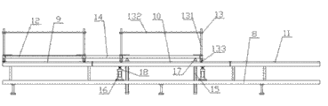
- CN203156844U CN203156844U CN 201320068730 CN201320068730U CN203156844U CN 203156844 U CN203156844 U CN 203156844U CN 201320068730 CN201320068730 CN 201320068730 CN 201320068730 U CN201320068730 U CN 201320068730U CN 203156844 U CN203156844 U CN 203156844U
- Authority
- CN
- China
- Prior art keywords
- slide rail
- frame
- dolly
- connects
- connects material
- Prior art date
- Legal status (The legal status is an assumption and is not a legal conclusion. Google has not performed a legal analysis and makes no representation as to the accuracy of the status listed.)
- Expired - Fee Related
Links
Images


Landscapes
- Intermediate Stations On Conveyors (AREA)
Abstract
本实用新型公开了一种取料堆垛机构,包括:叠料机构、废料收集筒和机架,在所述的机架上设置有冲切机构、送料滑轨和退料滑轨,在送料滑轨上滑动设置有送料板,送料板与设置在机架上的送料驱动装置相连接,在退料滑轨上滑动设置有退料机构。优点是:可以对成品料进行自动退料叠料,对废料进行自动收料,提高了工作效率,节约了劳动力,降低了加工成本,机械化程度高,满足EVA行业的加工需要。

The utility model discloses a material retrieving and stacking mechanism, which comprises: a material stacking mechanism, a waste material collection barrel and a frame. A punching mechanism, a feeding slide rail and a material returning slide rail are arranged on the frame. A feeding plate is slidably arranged on the slide rail, and the feeding plate is connected with a feeding driving device arranged on the frame, and a material return mechanism is slidably provided on the material return slide rail. The advantages are: it can automatically return and stack finished materials, and automatically collect waste materials, which improves work efficiency, saves labor, reduces processing costs, and has a high degree of mechanization to meet the processing needs of the EVA industry.
Description
技术领域 technical field
本实用新型涉及到一种成型机,尤其涉及一种EVA鞋底成型机的取料堆垛机构。 The utility model relates to a molding machine, in particular to a material retrieving and stacking mechanism of an EVA shoe sole molding machine.
背景技术 Background technique
现有的EVA鞋底成型机需要人工送料,冲切机构进行冲切后,需要人工将成品和废料分开拿走,工作效率低,机械化程度不好,收料不方便。 The existing EVA sole forming machine needs manual feeding, and after punching by the punching mechanism, the finished product and waste need to be taken away manually, the work efficiency is low, the degree of mechanization is not good, and the receiving is inconvenient. the
发明内容 Contents of the invention
本实用新型所要解决的技术问题是:提供一种工作效率高的取料堆垛机构。 The technical problem to be solved by the utility model is to provide a retrieving and stacking mechanism with high working efficiency.
为了解决上述技术问题,本实用新型采用的技术方案是:取料堆垛机构,包括:叠料机构、废料收集筒和机架,在所述的机架上设置有冲切机构、送料滑轨和退料滑轨,在送料滑轨上滑动设置有送料板,送料板与设置在机架上的送料驱动装置相连接,在退料滑轨上滑动设置有退料机构;所述退料机构包括:滑动设置在退料滑轨上的退料架、退料架驱动装置和定位架,在定位架上均匀设置有若干定位针,在退料架设置有若干出料气缸、压料升降气缸和定位气缸,出料气缸的出料活塞杆与成品料相抵,压料升降气缸的压料活塞杆与废料相抵,定位气缸的定位活塞杆与定位架相连接。 In order to solve the above-mentioned technical problems, the technical solution adopted by the utility model is: a material retrieving and stacking mechanism, including: a material stacking mechanism, a waste material collection tube and a frame, and a punching mechanism and a feeding slide rail are arranged on the frame And the material return slide rail, a feed plate is slidably arranged on the feed slide rail, the feed plate is connected with the feed drive device arranged on the frame, and a material return mechanism is slid on the material return slide rail; the material return mechanism Including: the ejection frame slidingly arranged on the ejection slide rail, the ejection frame driving device and the positioning frame, a number of positioning pins are uniformly arranged on the positioning frame, and a number of discharging cylinders and pressing lifting cylinders are arranged on the ejecting frame With the positioning cylinder, the discharge piston rod of the discharge cylinder is offset against the finished material, the pressure piston rod of the pressure lifting cylinder is offset against the waste, and the positioning piston rod of the positioning cylinder is connected with the positioning frame.
为了更好地解决上述技术问题,本实用新型采用的进一步技术方案是:所述叠料机构包括:接料架,在接料架上分别设置有前段接料小车滑轨、中段接料小车滑轨和后段接料小车滑轨,在前段接料小车滑轨和中段接料小车滑轨设置有接料小车一和接料小车二,接料小车一和接料小车二之间通过连杆活动连接,接料小车二和接料小车一结构相同其结构包括:车架,滑动设置在车架上的托盘和设置在车架下端的车轮,在中段接料小车滑轨下端的接料架上均匀设置有若干托盘复位气缸和升降气缸,托盘复位气缸的复位活塞杆与托盘相抵,升降气缸的升降活塞杆与中段接料小车滑轨的下端相抵。 In order to better solve the above-mentioned technical problems, the further technical solution adopted by the utility model is: the material stacking mechanism includes: a material receiving rack, on which are respectively provided with front section material receiving trolley slide rails and middle section material receiving trolley slide rails. Rail and the rear section of the receiving trolley slide rail, the front section of the material receiving trolley slide rail and the middle section of the material receiving trolley slide rail are provided with the first receiving trolley and the second receiving trolley, and the connecting rod between the first receiving trolley and the second receiving trolley Movable connection, material receiving trolley 2 and material receiving trolley 1 have the same structure. Its structure includes: frame, trays slidingly set on the frame and wheels set at the lower end of the frame, and material receiving frame at the lower end of the slide rail of the middle material receiving trolley Some pallet reset cylinders and lifting cylinders are evenly arranged on the top, the reset piston rod of the pallet reset cylinder is offset against the pallet, and the lifting piston rod of the lift cylinder is offset against the lower end of the middle section receiving trolley slide rail.
为了更好地解决上述技术问题,本实用新型采用的进一步技术方案是:所述叠料机构包括:接料支架、设置在接料架上的输送带、输送带驱动装置和输送带升降机构。 In order to better solve the above technical problems, the further technical solution adopted by the utility model is: the stacking mechanism includes: a material receiving bracket, a conveyor belt arranged on the material receiving frame, a conveyor belt driving device and a conveyor belt lifting mechanism.
为了更好地解决上述技术问题,本实用新型采用的进一步技术方案是:所述的输送带升降机构包括:均匀设置在接料支架上的若干输送带升降气缸,输送带升降气缸的活塞杆的上端与输送带相连接。 In order to better solve the above-mentioned technical problems, the further technical solution adopted by the utility model is: the conveyor belt lifting mechanism includes: several conveyor belt lifting cylinders evenly arranged on the material receiving support, the piston rod of the conveyor belt lifting cylinder The upper end is connected with the conveyor belt.
为了更好地解决上述技术问题,本实用新型采用的进一步技术方案是:所述的退料架驱动装置包括:电机、与电机相连接的减速机、传动链轮和传动链条。 In order to better solve the above-mentioned technical problems, the further technical solution adopted by the utility model is: the driving device of the stripping frame includes: a motor, a reducer connected with the motor, a transmission sprocket and a transmission chain.
本实用新型的优点是:上述取料堆垛机构,可以对成品料进行自动退料叠料,对废料进行自动收料,提高了工作效率,节约了劳动力,降低了加工成本,机械化程度高,满足EVA行业的加工需要。 The utility model has the advantages that: the above-mentioned retrieving and stacking mechanism can automatically return and stack finished materials and automatically collect waste materials, which improves work efficiency, saves labor, reduces processing costs, and has a high degree of mechanization. Meet the processing needs of the EVA industry. the
附图说明 Description of drawings
图1为本实用新型取料堆垛机构的结构示意图。 Fig. 1 is a schematic structural view of the reclaiming and stacking mechanism of the utility model.
图2为图1的俯视结构示意图。 FIG. 2 is a schematic top view of the structure of FIG. 1 .
图3为图1中叠料机构的结构示意图。 Fig. 3 is a structural schematic diagram of the stacking mechanism in Fig. 1 .
图4为图3的侧视结构示意图。 FIG. 4 is a schematic side view of the structure of FIG. 3 .
图5为图1中退料机构的结构示意图。 Fig. 5 is a schematic structural diagram of the material return mechanism in Fig. 1 .
图6为本实用新型取料堆垛机构中输送带叠料机构的结构示意图。 Fig. 6 is a schematic structural view of the conveyor belt stacking mechanism in the retrieving and stacking mechanism of the present invention.
图中:1、废料收集筒,2、机架,3、冲切机构,4、送料滑轨,5、退料滑轨,6、送料板,7、送料驱动装置,8、接料架,9、前段接料小车滑轨,10、中段接料小车滑轨,11、后段接料小车滑轨,12、接料小车一,13、接料小车二,131、车架,132、托盘,133、车轮,14、连杆,15、托盘复位气缸,16、升降气缸,17、复位活塞杆,18、升降活塞杆,19、退料架,20、定位架,21、定位针,22、出料气缸,23、压料升降气缸,231、压料活塞杆,24、定位气缸,241、定位活塞杆,25、出料活塞杆,26、接料支架,27、输送带升降气缸,28、活塞杆,29、输送带,30、输送带驱动装置,31、电机,32、减速机,33、传动链轮,34、传动链条,35、料子。 In the figure: 1. waste material collection cylinder, 2. frame, 3. punching mechanism, 4. feeding slide rail, 5. material return slide rail, 6. feeding plate, 7. feeding driving device, 8. receiving rack, 9. The slide rail of the feeding trolley in the front section, 10, the slide rail of the feeding trolley in the middle section, 11, the slide rail of the feeding trolley in the rear section, 12, the first feeding trolley, 13, the second feeding trolley, 131, the frame, 132, the tray , 133, wheel, 14, connecting rod, 15, pallet reset cylinder, 16, lift cylinder, 17, reset piston rod, 18, lift piston rod, 19, stripping frame, 20, positioning frame, 21, positioning pin, 22 , Discharging cylinder, 23, pressing lifting cylinder, 231, pressing piston rod, 24, positioning cylinder, 241, positioning piston rod, 25, discharging piston rod, 26, receiving bracket, 27, conveyor belt lifting cylinder, 28, piston rod, 29, conveyor belt, 30, conveyor belt driving device, 31, motor, 32, reducer, 33, drive sprocket, 34, drive chain, 35, material.
具体实施方式 Detailed ways
下面结合附图和具体实施例详细描述一下本实用新型的具体内容。 The specific content of the present utility model is described in detail below in conjunction with accompanying drawing and specific embodiment.
如图1、图2、图3、图4、图5所示,取料堆垛机构,包括:叠料机构、废料收集筒1和机架2,在所述的机架2上设置有冲切机构3、送料滑轨4和退料滑轨5,在送料滑轨4上滑动设置有送料板6,送料板6与设置在机架2上的送料驱动装置7相连接,在退料滑轨5上滑动设置有退料机构;所述退料机构包括:滑动设置在退料滑轨5上的退料架19、退料架驱动装置和定位架20,在定位架20上均匀设置有若干定位针21,在退料架19设置有若干出料气缸22、压料升降气缸23和定位气缸24,出料气缸22的出料活塞杆25与成品料相抵,压料升降气缸23的压料活塞杆231与废料相抵,定位气缸24的定位活塞杆241与定位架20相连接。 As shown in Fig. 1, Fig. 2, Fig. 3, Fig. 4, and Fig. 5, the retrieving and stacking mechanism includes: a stacking mechanism, a waste collection tube 1 and a frame 2, and a punching machine is arranged on the frame 2. Cutting mechanism 3, feeding slide rail 4 and material return slide rail 5, on the feed slide rail 4, a feed plate 6 is slidably arranged, and the feed plate 6 is connected with the feeding driving device 7 arranged on the frame 2, and the material return slide Rail 5 slides and is provided with the material return mechanism; Said material return mechanism comprises: the material return frame 19 that is slidably arranged on the material return slide rail 5, the material return frame driving device and the positioning frame 20, and the positioning frame 20 is evenly arranged with Some positioning pins 21 are provided with some discharging cylinders 22, pressing material lifting cylinders 23 and positioning cylinders 24 at the material return rack 19. The material piston rod 231 offsets the waste material, and the positioning piston rod 241 of the positioning cylinder 24 is connected with the positioning frame 20.
如图1所示,在本实施例中,所述叠料机构包括:接料架8,在接料架8上分别设置有前段接料小车滑轨9、中段接料小车滑轨10和后段接料小车滑轨11,在前段接料小车滑轨9和中段接料小车滑轨10设置有接料小车一12和接料小车二13,接料小车一12和接料小车二13之间通过连杆14活动连接,接料小车二13和接料小车一12结构相同其结构包括:车架131,滑动设置在车架131上的托盘132和设置在车架131下端的车轮133,在中段接料小车滑轨10下端的接料架8上均匀设置有若干托盘复位气缸15和升降气缸16,托盘复位气缸15的复位活塞杆17与托盘132相抵,升降气缸16的升降活塞杆18与中段接料小车滑轨10的下端相抵。
As shown in Figure 1, in this embodiment, the stacking mechanism includes: a
如图1所示,在本实施例中,所述的退料架驱动装置包括:电机31、与电机31相连接的减速机32、传动链轮33和传动链条34。 As shown in FIG. 1 , in this embodiment, the drive device for the stripping frame includes: a motor 31 , a reducer 32 connected to the motor 31 , a transmission sprocket 33 and a transmission chain 34 .
如图1、图2、图5所示,上述取料堆垛机构使用时,料子35放在送料板6上,由送料驱动装置7驱动送料板6将料子35送进冲切机构3进行冲切,冲切完成后进入退料位,定位气缸24下行推动定位架20和定位架20上的定位针21下行,戳住料子35,送料板6在送料驱动装置7的作用下推出,压料升降气缸23下行压住料子35的边缘定位,出料气缸22下行将成品料冲到托板122上,然后压料升降气缸23和出料气缸22上升,整个退料机构在退料架驱动装置的作用下移动到废料收集区,定位气缸24上升,废料与定位针21分离掉入废料收集筒1内。 As shown in Figure 1, Figure 2, and Figure 5, when the above-mentioned retrieving and stacking mechanism is in use, the material 35 is placed on the feeding plate 6, and the feeding drive device 7 drives the feeding plate 6 to send the material 35 into the punching mechanism 3 for punching. After cutting and punching, it enters the material return position, and the positioning cylinder 24 pushes the positioning frame 20 and the positioning pin 21 on the positioning frame 20 downward to poke the material 35, and the feeding plate 6 is pushed out under the action of the feeding drive device 7, pressing the material The lifting cylinder 23 goes down to press the edge of the material 35 for positioning, and the discharge cylinder 22 goes down to rush the finished material onto the pallet 122, and then the lifting cylinder 23 and the discharge cylinder 22 rise up, and the entire material return mechanism is on the drive device of the return rack. Move to the waste material collection area under the action of the action, the positioning cylinder 24 rises, and the waste material separates from the positioning pin 21 and falls in the waste material collection tube 1.
如图1、图2、图3、图4所示,所述叠料机构的工原理是:接料时,接料小车一12处在前段接料小车滑轨9上方的待接料位置,接料小车二13处在中段接料小车滑轨10上的接料位置,升降气缸16上升,将中段接料小车滑轨10抬升,托盘复位气缸15上升,将托盘132顶升至图3所示的高位,成品料依次落在托盘132上,挤压托盘132向下运动,当达到设定数量时,中段接料小车滑轨10下降到与前段接料小车滑轨9和后段接料小车滑轨11水平位置,推动接料小车一12,使接料小车二13到达后段接料小车滑轨11上方的卸料位,接料小车一12到达中段接料小车滑轨10上方的接料位。重复上述叠料动作,完成后,推动接料小车二13,使接料小车二13到达中段接料小车滑轨10上方的接料位,接料小车一12到达前段接料小车滑轨9上方的待接料位置。按照上述过程循环实现自动叠料、卸料。
As shown in Fig. 1, Fig. 2, Fig. 3 and Fig. 4, the working principle of the described material stacking mechanism is: when receiving materials, the material receiving trolley 12 is in the position to be received above the front segment material receiving trolley slide rail 9, The material receiving trolley 2 13 is in the material receiving position on the middle section material receiving
在实际应用过程中,输送装置还可以采用输送带,所述叠料机构包括:接料支架26、设置在接料架26上的输送带29、输送带驱动装置30和输送带升降机构。如图6所示,在本实施例中,所述的输送带升降机构包括:均匀设置在接料支架26上的若干输送带升降气缸27,输送带升降气缸27的活塞杆28的上端与输送带29相连接。在实际应用过程中,还可以采用丝杠、链条等输送带升降机构对输送带29进行升降。
In practical application, the conveying device can also be a conveyor belt, and the stacking mechanism includes: a
使用时,输送带升降气缸27上升,将输送带29推送到如图6所示位置,成品料依次落在输送带29上,输送带升降气缸27的活塞杆28依次向下运动,当达到设定数量时,由输送带驱动装置30驱动输送带29将成品料送到卸料区卸料。
During use, the conveyor
Claims (5)
Priority Applications (1)
| Application Number | Priority Date | Filing Date | Title |
|---|---|---|---|
| CN 201320068730 CN203156844U (en) | 2013-02-06 | 2013-02-06 | Material taking and stacking mechanism |
Applications Claiming Priority (1)
| Application Number | Priority Date | Filing Date | Title |
|---|---|---|---|
| CN 201320068730 CN203156844U (en) | 2013-02-06 | 2013-02-06 | Material taking and stacking mechanism |
Publications (1)
| Publication Number | Publication Date |
|---|---|
| CN203156844U true CN203156844U (en) | 2013-08-28 |
Family
ID=49018064
Family Applications (1)
| Application Number | Title | Priority Date | Filing Date |
|---|---|---|---|
| CN 201320068730 Expired - Fee Related CN203156844U (en) | 2013-02-06 | 2013-02-06 | Material taking and stacking mechanism |
Country Status (1)
| Country | Link |
|---|---|
| CN (1) | CN203156844U (en) |
Cited By (2)
| Publication number | Priority date | Publication date | Assignee | Title |
|---|---|---|---|---|
| CN103112040A (en) * | 2013-02-06 | 2013-05-22 | 盐城市华森机械有限公司 | Material taking and stacking mechanism |
| CN106738009A (en) * | 2016-11-23 | 2017-05-31 | 青岛双星名人实业股份有限公司橡塑分公司 | A kind of material for automatic cutting machine removes device |
-
2013
- 2013-02-06 CN CN 201320068730 patent/CN203156844U/en not_active Expired - Fee Related
Cited By (2)
| Publication number | Priority date | Publication date | Assignee | Title |
|---|---|---|---|---|
| CN103112040A (en) * | 2013-02-06 | 2013-05-22 | 盐城市华森机械有限公司 | Material taking and stacking mechanism |
| CN106738009A (en) * | 2016-11-23 | 2017-05-31 | 青岛双星名人实业股份有限公司橡塑分公司 | A kind of material for automatic cutting machine removes device |
Similar Documents
| Publication | Publication Date | Title |
|---|---|---|
| CN103112040A (en) | Material taking and stacking mechanism | |
| CN202245356U (en) | A device for automatically arranging non-specific shape ferrite blank products | |
| CN105855359B (en) | A kind of steel plate places crawl clamping punching integrated machine automatically | |
| CN104085694A (en) | Automatic mismatched discharge mechanism | |
| CN105013968B (en) | A kind of automatic feeding stamping equipment | |
| CN103317709B (en) | Full-automatic plate plastics sucking moulding machine | |
| CN105328064B (en) | Automatic feeding and discharging production line for plates | |
| CN111739721A (en) | A kind of ultra-thin inductance hot pressing molding process connection equipment | |
| CN106276340A (en) | A kind of thin slice automatic charging device | |
| CN106475712B (en) | An automatic loading and unloading device | |
| CN204657229U (en) | A kind of enamel pan inner metallic layer conveying molding device | |
| CN205263222U (en) | Automatic change aging testing production line | |
| CN105128141A (en) | Full-automatic tile manufacturing machine | |
| CN207344717U (en) | A kind of intelligence molding production equipment | |
| CN205112080U (en) | Automatic tile machinery | |
| CN203305507U (en) | Full-automatic sheet material plastic suction molding machine | |
| CN110238257A (en) | Full-automatic aluminum plate profiling production line | |
| CN205950190U (en) | An automatic loading and unloading assembly machine for the C tube of the liquid reservoir | |
| CN205253950U (en) | A plate automatic loading and unloading production line | |
| CN209698039U (en) | Carbon-chromium ferroalloy powder conveying molding device | |
| CN104816345A (en) | Shoe sole punching, beating and conveying device | |
| CN205122554U (en) | Full -automatic substrate arranging machine | |
| CN204384461U (en) | Multilayer receives base machine | |
| CN204844905U (en) | Film pre-composite automatic production line | |
| CN211168839U (en) | A gravity separation device for stacking parts |
Legal Events
| Date | Code | Title | Description |
|---|---|---|---|
| C14 | Grant of patent or utility model | ||
| GR01 | Patent grant | ||
| CF01 | Termination of patent right due to non-payment of annual fee |
Granted publication date: 20130828 Termination date: 20200206 |
|
| CF01 | Termination of patent right due to non-payment of annual fee |