CN203146166U - Pipe body structure of joint pipe of air inlet pipe and air outlet pipe of internal combustion engine - Google Patents
Pipe body structure of joint pipe of air inlet pipe and air outlet pipe of internal combustion engine Download PDFInfo
- Publication number
- CN203146166U CN203146166U CN201320128224.1U CN201320128224U CN203146166U CN 203146166 U CN203146166 U CN 203146166U CN 201320128224 U CN201320128224 U CN 201320128224U CN 203146166 U CN203146166 U CN 203146166U
- Authority
- CN
- China
- Prior art keywords
- pipe
- combustion engine
- internal combustion
- body structure
- air
- Prior art date
- Legal status (The legal status is an assumption and is not a legal conclusion. Google has not performed a legal analysis and makes no representation as to the accuracy of the status listed.)
- Expired - Fee Related
Links
- 238000002485 combustion reaction Methods 0.000 title claims abstract description 24
- 238000005266 casting Methods 0.000 abstract description 2
- 208000031872 Body Remains Diseases 0.000 abstract 1
- 238000004519 manufacturing process Methods 0.000 abstract 1
- 210000003205 muscle Anatomy 0.000 description 8
- 230000009286 beneficial effect Effects 0.000 description 1
- 230000000694 effects Effects 0.000 description 1
- 230000007774 longterm Effects 0.000 description 1
- 238000000034 method Methods 0.000 description 1
Images



Classifications
-
- Y—GENERAL TAGGING OF NEW TECHNOLOGICAL DEVELOPMENTS; GENERAL TAGGING OF CROSS-SECTIONAL TECHNOLOGIES SPANNING OVER SEVERAL SECTIONS OF THE IPC; TECHNICAL SUBJECTS COVERED BY FORMER USPC CROSS-REFERENCE ART COLLECTIONS [XRACs] AND DIGESTS
- Y02—TECHNOLOGIES OR APPLICATIONS FOR MITIGATION OR ADAPTATION AGAINST CLIMATE CHANGE
- Y02T—CLIMATE CHANGE MITIGATION TECHNOLOGIES RELATED TO TRANSPORTATION
- Y02T10/00—Road transport of goods or passengers
- Y02T10/10—Internal combustion engine [ICE] based vehicles
- Y02T10/12—Improving ICE efficiencies
Landscapes
- Exhaust Silencers (AREA)
Abstract
The utility model discloses a pipe body structure of a joint pipe of an air inlet pipe and an air outlet pipe of an internal combustion engine. The pipe body structure is optimized and improved on the basis of a traditional joint pipe of the air inlet pipe and the air outlet pipe. One or more reinforced ribs are distributed on the pipe wall of a pipe body of the joint pipe in the direction of the joint pipe, the section of each reinforced rib is U-shaped or V-shaped, the reinforced ribs are concave towards the inside of the pipe body, and the wall thickness of the pipe body remains unchanged so that good casting performance can be guaranteed. The pipe body structure is simple in structure, easy to manufacture, practical, good in reliability and even in thickness of the pipe wall, and the flow indirection inside the pipe body is good.
Description
Technical field
The utility model relates to a kind of internal combustion engine air-exhausting air-entering adapter tube body structure.
Background technique
It generally is to be connected in series on the pipeline of internal combustion (IC) engine air-inlet-exhaust system that internal combustion engine air-exhausting air-entering is taken over (air-intake of combustion engine is taken over or vent connection), plays the effect of transportation gas.The body cross section that traditional internal combustion engine air-exhausting air-entering is taken over is ring, be not furnished with reinforced rib on the body, so intensity is lower, and under the operating mode of the long-term vibration of internal-combustion engine, fracture is easily taken in traditional intake and exhaust, and reliability is relatively low.
Summary of the invention
The purpose of this utility model is to provide that design has reinforced rib on a kind of internal combustion engine air-exhausting air-entering adapter tube body that restrains the newspaper prior art, good rigidly, and the intensity height is not easy fracture.Improve rigidity and intensity that internal combustion engine air-exhausting air-entering is taken over, improve the reliability of its work.The rib wall thickness is even, and the internal combustion engine air-exhausting air-entering body of good castability is in conjunction with structure.
Technical solution of the present utility model is such, a kind of internal combustion engine air-exhausting air-entering adapter tube body structure, comprise rib, the first spill muscle, the second spill muscle, intake and exhaust adapter, it is characterized in that on intake and exhaust adapters (10) the pipe outer wall rib (1) being arranged, rib (1) is the concave bar bar.
Rib (1) is on the vent connection tube wall is axial.
The beneficial effects of the utility model are:
1, be provided with reinforced rib because internal combustion engine air-exhausting air-entering of the present utility model is taken at body, therefore rigidity and the intensity of taking over all is improved.
2, reduce the rate of fault that fracture is taken in intake and exhaust, improve the reliability of internal combustion engine effectively.
3, because rib is to dent into body inside, therefore can not influence the outward appearance that internal combustion engine air-exhausting air-entering is taken over.
4, the wall thickness at rib place keeps evenly constant, therefore maintains advantages of good casting.
Description of drawings
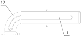
Fig. 1 is the axonometric drawing of the utility model internal combustion engine air-exhausting air-entering adapter tube body structure.
Fig. 2 is the plan view of the utility model internal combustion engine air-exhausting air-entering adapter tube body structure.
Fig. 3 is the sectional view of the utility model internal combustion engine air-exhausting air-entering adapter tube body structure.
Fig. 4 is the sectional view of the utility model internal combustion engine air-exhausting air-entering adapter tube body structure.
Among Fig. 1~Fig. 4, (10) are taken in rib (1), the first spill muscle (2), the second spill muscle (3), intake and exhaust.
Embodiment
Below in conjunction with accompanying drawing, a concrete case study on implementation of internal combustion engine air-exhausting air-entering adapter tube body structure of the present utility model is described:
Illustrated in figures 1 and 2 is the surface structure that air-intake of combustion engine is taken over the body of (10), is provided with rib (1) at tube wall, and along the layout of moving towards of pipeline, rib (1) dents on the tube wall rib (1) on tube wall.
As shown in Figure 3 and Figure 4, the cross section structure of rib (1) is the first spill muscle (2), or the second spill muscle (3), and the first spill muscle (2) is " U " font, and the second spill muscle (3) is " V " font.It is consistent with former pipe shaft wall thickness that the wall thickness of the section of rib (1) keeps.
Claims (2)
1. an internal combustion engine air-exhausting air-entering adapter tube body structure is characterized in that on intake and exhaust adapter (10) tube wall rib (1) being arranged, and rib (1) is the concave bar bar.
2. according to the described internal combustion engine air-exhausting air-entering adapter tube body of claim 1 structure, it is characterized in that rib (1) is on intake and exhaust adapter tube wall is axial.
Priority Applications (1)
| Application Number | Priority Date | Filing Date | Title |
|---|---|---|---|
| CN201320128224.1U CN203146166U (en) | 2013-03-20 | 2013-03-20 | Pipe body structure of joint pipe of air inlet pipe and air outlet pipe of internal combustion engine |
Applications Claiming Priority (1)
| Application Number | Priority Date | Filing Date | Title |
|---|---|---|---|
| CN201320128224.1U CN203146166U (en) | 2013-03-20 | 2013-03-20 | Pipe body structure of joint pipe of air inlet pipe and air outlet pipe of internal combustion engine |
Publications (1)
| Publication Number | Publication Date |
|---|---|
| CN203146166U true CN203146166U (en) | 2013-08-21 |
Family
ID=48973700
Family Applications (1)
| Application Number | Title | Priority Date | Filing Date |
|---|---|---|---|
| CN201320128224.1U Expired - Fee Related CN203146166U (en) | 2013-03-20 | 2013-03-20 | Pipe body structure of joint pipe of air inlet pipe and air outlet pipe of internal combustion engine |
Country Status (1)
| Country | Link |
|---|---|
| CN (1) | CN203146166U (en) |
Cited By (1)
| Publication number | Priority date | Publication date | Assignee | Title |
|---|---|---|---|---|
| CN105065102A (en) * | 2015-07-21 | 2015-11-18 | 力帆实业(集团)股份有限公司 | Exhaust pipe mounting structure and motorcycle |
-
2013
- 2013-03-20 CN CN201320128224.1U patent/CN203146166U/en not_active Expired - Fee Related
Cited By (1)
| Publication number | Priority date | Publication date | Assignee | Title |
|---|---|---|---|---|
| CN105065102A (en) * | 2015-07-21 | 2015-11-18 | 力帆实业(集团)股份有限公司 | Exhaust pipe mounting structure and motorcycle |
Similar Documents
| Publication | Publication Date | Title |
|---|---|---|
| EP2128394A3 (en) | Engine exhaust cooler and air pre-cleaner aspirator | |
| ATE547613T1 (en) | COMBUSTION ENGINE WITH COMPRESSOR WITH FIRST AND SECOND AUXILIARY INTAKES | |
| CN204458107U (en) | The mixing arrangement of gas recirculation system | |
| FI20115243L (en) | Procedure for upgrading an engine, upgrade kit for an engine and internal combustion engine | |
| ATE542033T1 (en) | EXHAUST MANIFOLD | |
| TR201403864A2 (en) | Internal combustion engine with charge-air cooler and exhaustgas recirculation arrangement, and method for producing an internal combustion engine of said type | |
| CN203488302U (en) | Fuel oil returning device | |
| CN201653692U (en) | Crankshaft case oil pumping amount measuring apparatus | |
| EP2735723A2 (en) | Fuel supply device and fuel-returning three-way pipe thereof | |
| CN202611861U (en) | Oil return device for supercharger | |
| CN202468094U (en) | Air intake manifold and engine and vehicle comprising air intake manifold | |
| CN203296936U (en) | Mechanical inertia air inflowing double-faced turbocharger | |
| CN204691937U (en) | A kind of four-cylinder internal combustion engine oil gas supply system | |
| FR2975972B1 (en) | TURBOREACTOR NACELLE AIR INTAKE STRUCTURE | |
| CN203081598U (en) | Diesel engine cylinder block | |
| CN206860323U (en) | With multi-functional engine air inlet tube | |
| CN206280155U (en) | A kind of multi-functional cover structure of overhead cam high-speed diesel engine | |
| CN201810377U (en) | Exhaust system of anti-explosion diesel | |
| CN205154356U (en) | Outer circulative cooling pipeline of engine | |
| CN111042961A (en) | Air inlet assembly and V-shaped engine | |
| CN204357529U (en) | A kind of crankcase bleeder | |
| CN203655400U (en) | High temperature resistant cast iron exhaust manifold | |
| CN205206987U (en) | Locomotive diesel engine organism | |
| CN204041179U (en) | Automobile eddy flow venting gas appliance | |
| CN203335226U (en) | Novel intercooling pipe |
Legal Events
| Date | Code | Title | Description |
|---|---|---|---|
| C14 | Grant of patent or utility model | ||
| GR01 | Patent grant | ||
| CF01 | Termination of patent right due to non-payment of annual fee |
Granted publication date: 20130821 Termination date: 20170320 |
|
| CF01 | Termination of patent right due to non-payment of annual fee |