CN203131998U - Industrial dehumidifier - Google Patents
Industrial dehumidifier Download PDFInfo
- Publication number
- CN203131998U CN203131998U CN 201320083917 CN201320083917U CN203131998U CN 203131998 U CN203131998 U CN 203131998U CN 201320083917 CN201320083917 CN 201320083917 CN 201320083917 U CN201320083917 U CN 201320083917U CN 203131998 U CN203131998 U CN 203131998U
- Authority
- CN
- China
- Prior art keywords
- shell
- air inlet
- dehumidification
- condenser
- evaporator
- Prior art date
- Legal status (The legal status is an assumption and is not a legal conclusion. Google has not performed a legal analysis and makes no representation as to the accuracy of the status listed.)
- Expired - Lifetime
Links
Images


Landscapes
- Drying Of Gases (AREA)
Abstract
本实用新型提供了一种工业除湿机,其在除湿机的壳体上增设至少一个开度可调的可变量进风口,在总循环风量一定的情况下,通过改变可变量进风口的开度达到直接调节改变冷凝器循环风量,间接影响蒸发器循环风量,使其既有利于蒸发器冷凝除湿,又利于冷凝器换热,降低压缩式换热循环功耗。具体通过实验室除湿工况进行充分模拟除湿环境,在不同的除湿工况下,测得若干的进风口开度下的除湿效率,优选出若干除湿工况下的进风口开度,这些实验测得的数据可以预置入整机控制程序以便根据实际工况自动调节可变量进风口的开度,也可以提供给使用者手动调节,从而在整机成本增加相对较低的情况下,实现除湿机随除湿环境而改变,达到除湿全过程能耗最低、效率最优。
The utility model provides an industrial dehumidifier, which adds at least one variable air inlet with adjustable opening on the housing of the dehumidifier, and when the total circulating air volume is constant, by changing the opening of the variable air inlet To directly adjust and change the circulating air volume of the condenser, and indirectly affect the circulating air volume of the evaporator, so that it is not only beneficial to the condensation and dehumidification of the evaporator, but also beneficial to the heat exchange of the condenser, and reduces the power consumption of the compression heat exchange cycle. Specifically, the dehumidification environment is fully simulated through laboratory dehumidification conditions. Under different dehumidification conditions, the dehumidification efficiency under certain air inlet openings is measured, and the air inlet openings under certain dehumidification conditions are optimized. These experimental measurements The data obtained can be preset into the control program of the whole machine so as to automatically adjust the opening of the variable air inlet according to the actual working conditions, and can also be provided to the user for manual adjustment, so as to achieve dehumidification with a relatively low increase in the cost of the whole machine The machine changes with the dehumidification environment to achieve the lowest energy consumption and the best efficiency in the whole process of dehumidification.
Description
技术领域 technical field
本实用新型涉及一种高能效除湿机,尤其适用仓库、车间等工业生产领域使用的具有单位时间较大除湿量,高效节能的工业除湿机。 The utility model relates to a high-energy-efficiency dehumidifier, which is especially suitable for high-efficiency and energy-saving industrial dehumidifiers with large dehumidification capacity per unit time and used in industrial production fields such as warehouses and workshops. the
背景技术 Background technique
工业用除湿机由于除湿量相对较大,输入功率高,长期使用等特点,对高效节能有突出的要求,如北美能源之星要求:35.5L/Day≤除湿量≤87.5L/Day的除湿机,能源效率≥2.80L/KWh,目前只有压缩式除湿机具有以上高能效的可能。但是现有压缩式除湿机,一般蒸发器与冷凝器循环风量相等,即使不相等,也不具备可调节变动的功能,然而除湿环境是动态变化的,而传统除湿机并不具备这种随除湿环境变化而变化的能力,进而不能实现除湿全过程能效最优,不能实现能耗的降低。中国专利申请号为201120471257.7的专利中公开了一种新型工业除湿机,适用于制药车间等领域,具有出气扇,排气扇,压缩机,热交换器等压缩式除湿机的基本零部件,但具体结构及效率状况不详。 Due to the characteristics of relatively large dehumidification capacity, high input power, and long-term use, industrial dehumidifiers have outstanding requirements for high efficiency and energy saving, such as North American Energy Star requirements: 35.5L/Day≤Dehumidification capacity≤87.5L/Day dehumidifiers , energy efficiency ≥ 2.80L/KWh, currently only the compression dehumidifier has the possibility of the above high energy efficiency. However, in existing compression dehumidifiers, the circulating air volumes of the evaporator and condenser are generally equal. Even if they are not equal, they do not have the function of adjustable changes. However, the dehumidification environment changes dynamically, and traditional dehumidifiers do not have this kind of dehumidification The ability to change due to environmental changes can not achieve the optimal energy efficiency of the whole dehumidification process, and cannot achieve the reduction of energy consumption. Chinese patent application number 201120471257.7 discloses a new type of industrial dehumidifier, which is suitable for pharmaceutical workshops and other fields. The specific structure and efficiency status is unknown. the
实用新型内容 Utility model content
本实用新型的目的在于提供一种工业除湿机,旨在实现在整机成本增加相对较低的情况下,达到除湿全过程能耗最低、效率最优的效果。 The purpose of the utility model is to provide an industrial dehumidifier, aiming to achieve the effect of the lowest energy consumption and the best efficiency in the whole process of dehumidification under the condition that the cost of the whole machine is relatively low. the
为解决上述技术问题,本实用新型采用的技术方案是:提供一种工业除湿机,包括顶盖、前壳、后壳、底盘和接水盘,以及由蒸发器、冷凝器与压缩机通过管道连接形成的压缩式制冷循环系统和用于实现空气循环的风道部件,所述前壳上设有固定进风口,所述后壳上设有排风口,所述蒸发器设于所述前壳 的内侧且正对所述固定进风口,所述冷凝器与所述蒸发器并列设置且所述蒸发器位于所述冷凝器与所述前壳之间,所述接水盘设于所述蒸发器和冷凝器的下方;还包括智能控制器以及与所述智能控制器连接的温度传感器、湿度传感器,所述后壳上还设有至少一个开度可调的、用于控制循环风量的可变量进风口。 In order to solve the above technical problems, the technical solution adopted by the utility model is to provide an industrial dehumidifier, including a top cover, a front shell, a rear shell, a chassis and a water tray, and an evaporator, a condenser and a compressor through a pipeline The formed compression refrigeration cycle system is connected with the air duct components used to realize air circulation, the front shell is provided with a fixed air inlet, the rear shell is provided with an air outlet, and the evaporator is arranged on the front The inner side of the shell is facing the fixed air inlet, the condenser and the evaporator are arranged side by side and the evaporator is located between the condenser and the front shell, and the water receiving tray is set on the Below the evaporator and condenser; it also includes an intelligent controller, a temperature sensor and a humidity sensor connected to the intelligent controller, and at least one adjustable opening for controlling the circulating air volume is also provided on the rear shell Variable air intake. the
具体地,所述可变量进风口为滑动门或者旋转门。 Specifically, the variable air inlet is a sliding door or a revolving door. the
进一步地,还包括由所述智能控制器根据所述温度传感器检测到的温度及所述湿度传感器检测到的湿度进行实时控制、用于带动所述滑动门滑动或者带动旋转门旋转以改变其开度的动力机构。 Further, it also includes that the intelligent controller performs real-time control according to the temperature detected by the temperature sensor and the humidity detected by the humidity sensor, and is used to drive the sliding door to slide or drive the revolving door to rotate to change its opening. Degree of power mechanism. the
进一步地,所述接水盘的下方还设有内置水箱,所述接水盘上设有内接排水口,所述内置水箱与所述内接排水口连接。 Further, a built-in water tank is provided under the water receiving tray, and an internal drain is provided on the water receiving tray, and the built-in water tank is connected to the internal drain. the
进一步地,所述接水盘上设有外接排水口。 Further, the water receiving tray is provided with an external drain port. the
进一步地,所述底盘的下方还设有至少两个滚轮和至少一个支撑脚,所述支撑脚设于所述两个滚轮的相异侧。 Further, at least two rollers and at least one supporting foot are provided under the chassis, and the supporting feet are arranged on different sides of the two rollers. the
进一步地,所述后壳上还设有把手,所述把手与所述滚轮位于同一侧。 Further, a handle is further provided on the rear shell, and the handle is located on the same side as the roller. the
具体地,所述冷凝器为U形结构,所述后壳具有左侧壳体和右侧壳体,所述左侧壳体和右侧壳体上分别设有一个可变量进风口。 Specifically, the condenser has a U-shaped structure, and the rear shell has a left shell and a right shell, and a variable air inlet is respectively provided on the left shell and the right shell. the
或者,具体地,所述冷凝器为L形结构,所述后壳具有左侧壳体和右侧壳体,所述左侧壳体和右侧壳体上分别设有一个可变量进风口。 Or, specifically, the condenser has an L-shaped structure, the rear shell has a left shell and a right shell, and a variable air inlet is respectively provided on the left shell and the right shell. the
或者,具体地,所述冷凝器为I形结构,所述后壳具有左侧壳体和右侧壳体,所述左侧壳体和右侧壳体上分别设有一个可变量进风口。 Or, specifically, the condenser has an I-shaped structure, the rear shell has a left shell and a right shell, and a variable air inlet is respectively provided on the left shell and the right shell. the
本实用新型提供的工业除湿机在常规除湿机的基础上进行改进,特别对蒸发器与冷凝器循环风量在单风道的基础上进行差异化设计,在总循环风量一定的情况下,直接调节改变冷凝器循环风量,间接影响蒸发器循环风量,使其既有利于蒸发器冷凝除湿,又利于冷凝器换热,降低压缩式换热循环功耗;本实用新型具体在其后壳两侧面增设可变量进风口,通过实验室除湿工况进行充分模拟除湿环境,在若干不同的除湿工况下,测得若干的进风口开度下的除湿效 率,优选出若干除湿工况下的进风口开度,适应不同进风量需求,这些实验测得的数据可以预置入整机控制程序以便根据实际工况自动调节可变量进风口的开度,也可以提供给使用者手动调节可变量进风口的开度,从而在整机成本增加相对较低的情况下,实现除湿机随除湿环境而改变,达到除湿全过程能耗最低、效率最优。 The industrial dehumidifier provided by the utility model is improved on the basis of conventional dehumidifiers, especially the circulating air volume of the evaporator and condenser is designed in a differentiated manner on the basis of a single air duct, and when the total circulating air volume is constant, it can be directly adjusted Changing the circulating air volume of the condenser indirectly affects the circulating air volume of the evaporator, making it not only beneficial to the condensation and dehumidification of the evaporator, but also beneficial to the heat exchange of the condenser, reducing the power consumption of the compression heat exchange cycle; The variable air inlet fully simulates the dehumidification environment through laboratory dehumidification conditions. Under several different dehumidification conditions, the dehumidification efficiency under certain air inlet openings is measured, and the air inlet under several dehumidification conditions is optimized. Opening, to meet the needs of different air intakes, the data measured by these experiments can be preset into the control program of the whole machine to automatically adjust the opening of the variable air inlet according to the actual working conditions, and can also be provided to the user to manually adjust the variable air inlet The opening degree, so that the dehumidifier can change with the dehumidification environment under the condition that the cost of the whole machine is relatively low, so as to achieve the lowest energy consumption and the best efficiency in the whole process of dehumidification. the
附图说明 Description of drawings
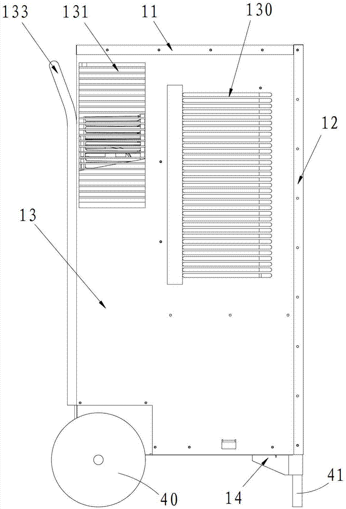
图1为本实用新型实施例提供的工业除湿机的左视图; Fig. 1 is the left view of the industrial dehumidifier provided by the utility model embodiment;
图2为本实用新型实施例提供的工业除湿机的右视图; Fig. 2 is the right side view of the industrial dehumidifier provided by the utility model embodiment;
图3为本实用新型实施例提供的工业除湿机的主视图; Fig. 3 is the front view of the industrial dehumidifier provided by the utility model embodiment;
图4为本实用新型实施例提供的工业除湿机的俯视图; Fig. 4 is the top view of the industrial dehumidifier provided by the utility model embodiment;
图5为本实用新型实施例提供的工业除湿机去除外壳后的左视图; Fig. 5 is the left view of the industrial dehumidifier provided by the embodiment of the utility model after removing the shell;
图6为本实用新型实施例提供的工业除湿机去除外壳后的主视图; Fig. 6 is the front view of the industrial dehumidifier provided by the embodiment of the present invention after removing the shell;
图7为沿图6中A-A线的剖视结构图(其中,冷凝器为U形结构); Fig. 7 is a sectional structure diagram along the A-A line in Fig. 6 (wherein, the condenser is a U-shaped structure);
图8为另一实施例将图7中的冷凝器替换为右向L形结构时的示意图; Fig. 8 is a schematic diagram when the condenser in Fig. 7 is replaced by a rightward L-shaped structure in another embodiment;
图9为另一实施例将图7中的冷凝器替换为左向L形结构时的示意图; Fig. 9 is a schematic diagram when the condenser in Fig. 7 is replaced by a leftward L-shaped structure in another embodiment;
图10为另一实施例将图7中的冷凝器替换为I形结构时的示意图。 Fig. 10 is a schematic diagram of another embodiment where the condenser in Fig. 7 is replaced with an I-shaped structure. the
具体实施方式 Detailed ways
为了使本实用新型所要解决的技术问题、技术方案及有益效果更加清楚明白,以下结合附图及实施例,对本实用新型进行进一步详细说明。应当理解,此处所描述的具体实施例仅仅用以解释本实用新型,并不用于限定本实用新型。 In order to make the technical problems, technical solutions and beneficial effects to be solved by the utility model clearer, the utility model will be further described in detail below in conjunction with the accompanying drawings and embodiments. It should be understood that the specific embodiments described here are only used to explain the utility model, and are not intended to limit the utility model. the
请一并参照图1至图6,现对本实用新型提供的工业除湿机进行说明。工业除湿机包括顶盖11、前壳12、后壳13、底盘14和接水盘15,以及蒸发器21、冷凝器22与压缩机23通过管道连接形成的压缩式制冷循环系统和用于实现空气循环的风道部件132,顶盖11、前壳12、后壳13、底盘14围合连接形 成容置腔,蒸发器21、冷凝器22与压缩机23设于该容置腔内,前壳12上述设有固定进风口120,后壳13上设有排风口131,蒸发器21设于前壳12的内侧且正对固定进风口120,冷凝器22与蒸发器21并列设置且蒸发器21位于冷凝器22与前壳12之间,接水盘15设于蒸发器21和冷凝器22的下方,用于收集除湿工作时的凝结水;可将蒸发器21、冷凝器22固定在接水盘15上,该工业除湿机还包括智能控制器10以及与智能控制器10连接的温度传感器(图中未示)、湿度传感器(图中未示),该智能控制器10设有智能控制电路及运行控制程序,温度传感器和湿度传感器最好设于固定进风口120处,以准确检测温度与湿度;更主要的是,后壳13上还设有至少一个开度可调的、用于控制循环风量的可变量进风口130。
Please refer to Fig. 1 to Fig. 6 together, and now the industrial dehumidifier provided by the utility model will be described. The industrial dehumidifier includes a
本实用新型提供的工业除湿机,当除湿机工作时环境空气从固定进风口120及可变量进风口130吸入,经过蒸发器21、冷凝器22、风道部件132,从排风口131排出,潮湿的环境空气经过低温蒸发器21会遇冷凝结出液态水排入接水盘15,降温除湿后的低温干燥空气紧接着流向高温冷凝器22,经高温冷凝器22加热后(同时冷却高温冷凝器22),在风道部件132的风扇作用下经排风口131排出,如此循环凝结水不断排出,使除湿环境空气湿度不断降低。
In the industrial dehumidifier provided by the utility model, when the dehumidifier is working, the ambient air is inhaled from the fixed
在总循环风量一定的情况下,直接调节改变冷凝器22循环风量,间接影响蒸发器21循环风量,使其既有利于蒸发器21冷凝除湿,又利于冷凝器22换热,降低压缩式换热循环功耗;而本实用新型中的可变量进风口130可以起到调节循环风量的作用,首先通过实验测得不同的除湿环境具有特定的湿度、温度,经过预先计算及试验确定特定除湿环境下可变量进风口130的开度大小,以满足除湿效率最优化,若干除湿环境下的可变量进风口130的开度大小的最优化数据预置到智能控制器10的控制程序中;可以在顶盖11或者其他位置设有若干按键111及显示屏110并与智能控制器10连通,用于人机交互指令设置,运行程序选择,或者选择自动运行等,也可根据特定除湿环境进行人工选择;固定进风口120处设置的湿度传感器、温度传感器检测到的人机交互数据,显示 到显示屏110上,使用者可根据预先设定的优化方案通过按键111控制可变量进风口130的开度大小,进而除湿机运行;也可进一步设置可通过控制器自动控制的机构控制可变量进风口130的开度大小,进而除湿机运行,实现除湿机随除湿环境而改变,达到除湿全过程能耗最低、效率最优。
When the total circulating air volume is constant, directly adjust and change the circulating air volume of the
参见图1及图2,对于可变量进风口130可以采用滑动门或者旋转门。这样通过滑动门板或者转动门板来实现改变进风口的大小开度,便于操作和自动控制,当然也可以是其它开关门和挡板结构,例如百叶窗结构;当采用自动控制时,本实用新型除湿机还要包括动力机构(图中未示),该动力机构由智能控制器根据温度传感器检测到的温度及湿度传感器检测到的湿度进行实时控制、用于带动滑动门滑动或者带动旋转门旋转以改变其开度,具体来说,该动力机构可以是采用电机带动的旋转机构,也可以是电机带动的伸缩机构或链轮机构,主要是能实现滑动门滑动或者旋转门旋转的机构均可,其中电机受智能控制器10的内部程序控制。
Referring to FIG. 1 and FIG. 2 , a sliding door or a revolving door can be used for the
参见图5及图6,接水盘15的下方还设有内置水箱3,用于承接冷凝水,接水盘15上设有内接排水口150,内置水箱3与内接排水口150连接;还可以在接水盘15上设有外接排水口151,用于接外置水箱或者外接排水管直接排入下水道,供不同的排水方式选择使用,方便凝结水排除。
Referring to Fig. 5 and Fig. 6, there is also a built-in
请参见图1至图6,本实用新型根据工业领域除湿空间大,需要移动到不同地点加快除湿效率的特点,底盘14的下方还设有至少两个滚轮40和至少一个支撑脚41,支撑脚41设于两个滚轮40的相异侧,本实用新型采用若干滚动轮与若干支撑脚混合搭配形式,既方便移动除湿,同时支撑脚41又可确保静置时整个设备稳定,避免底部仅仅采用若干滚轮,若无额外制动装置容易发生意外移动的危险。因此为了兼顾设备移动与静置,本实施例中,底盘14的前端设置两个支撑脚41,后端设有两个滚轮40,分布于除湿机的两侧。
Please refer to Fig. 1 to Fig. 6, according to the characteristics of large dehumidification space in the industrial field and the need to move to different places to speed up the dehumidification efficiency, the utility model is provided with at least two
参见图1、图2及图4,为了方便除湿机的移动,后壳13上还设有把手133,把手133与滚轮40位于除湿机的同一侧,当移动除湿机时,拉动把手133使底 盘14的支撑脚41离地,以利用滚轮40移动除湿机。
Referring to Fig. 1, Fig. 2 and Fig. 4, in order to facilitate the movement of the dehumidifier, a
请参见图7,后壳13具有左侧壳体和右侧壳体,本实用新型在传统家用除湿机单风道,蒸发器21、冷凝器22相等循环风量的基础上,充分利用工业除湿机除湿量大,结构空间充足,通过将冷凝器22设计为U形结构,在左侧壳体和右侧壳体上于冷凝器22的两侧分别设有一个可变量进风口130,从而扩大冷凝器22循环风,进一步改善冷凝器22换热,加大冷凝器22的换热效率,提高整机能效,达到特定除湿环境效率最大化、除湿全过程效率最大化。
Please refer to Fig. 7, the
参见图8及图9,作为替代方案,冷凝器22也可以设计成L形,还可以设计成图10所示的I形。
Referring to FIG. 8 and FIG. 9 , as an alternative, the
当然,对于上述可变量进风口130,除在后壳13的左右两侧同时设置外,也可在其中一侧甚至上侧单独设置,凡是采用单风道实现冷凝器22与蒸发器21差异化循环风量的除湿机都在本实用新型的保护范围之内。
Of course, for the above-mentioned
以上所述仅为本实用新型的较佳实施例而已,并不用以限制本实用新型,凡在本实用新型的精神和原则之内所作的任何修改、等同替换和改进等,均应包含在本实用新型的保护范围之内。 The above descriptions are only preferred embodiments of the present utility model, and are not intended to limit the present utility model. Any modifications, equivalent replacements and improvements made within the spirit and principles of the present utility model shall be included in this utility model. within the scope of protection of utility models. the
Claims (10)
Priority Applications (1)
| Application Number | Priority Date | Filing Date | Title |
|---|---|---|---|
| CN 201320083917 CN203131998U (en) | 2013-02-22 | 2013-02-22 | Industrial dehumidifier |
Applications Claiming Priority (1)
| Application Number | Priority Date | Filing Date | Title |
|---|---|---|---|
| CN 201320083917 CN203131998U (en) | 2013-02-22 | 2013-02-22 | Industrial dehumidifier |
Publications (1)
| Publication Number | Publication Date |
|---|---|
| CN203131998U true CN203131998U (en) | 2013-08-14 |
Family
ID=48939972
Family Applications (1)
| Application Number | Title | Priority Date | Filing Date |
|---|---|---|---|
| CN 201320083917 Expired - Lifetime CN203131998U (en) | 2013-02-22 | 2013-02-22 | Industrial dehumidifier |
Country Status (1)
| Country | Link |
|---|---|
| CN (1) | CN203131998U (en) |
Cited By (3)
| Publication number | Priority date | Publication date | Assignee | Title |
|---|---|---|---|---|
| CN104006454A (en) * | 2013-02-22 | 2014-08-27 | 广东美的集团芜湖制冷设备有限公司 | Industrial dehumidifier |
| CN105757807A (en) * | 2016-05-10 | 2016-07-13 | 合肥天鹅制冷科技有限公司 | Dehumidifier with air volume regulation function |
| CN109812879A (en) * | 2018-12-27 | 2019-05-28 | 宁波保税区瑞丰模具科技有限公司 | A kind of dehumidifier of other aeration structure |
-
2013
- 2013-02-22 CN CN 201320083917 patent/CN203131998U/en not_active Expired - Lifetime
Cited By (4)
| Publication number | Priority date | Publication date | Assignee | Title |
|---|---|---|---|---|
| CN104006454A (en) * | 2013-02-22 | 2014-08-27 | 广东美的集团芜湖制冷设备有限公司 | Industrial dehumidifier |
| CN104006454B (en) * | 2013-02-22 | 2017-04-05 | 广东美的集团芜湖制冷设备有限公司 | Industrial dehumidifier |
| CN105757807A (en) * | 2016-05-10 | 2016-07-13 | 合肥天鹅制冷科技有限公司 | Dehumidifier with air volume regulation function |
| CN109812879A (en) * | 2018-12-27 | 2019-05-28 | 宁波保税区瑞丰模具科技有限公司 | A kind of dehumidifier of other aeration structure |
Similar Documents
| Publication | Publication Date | Title |
|---|---|---|
| CN104019643B (en) | Agricultural product heat pump drying system with waste heat recovery | |
| CN103099302B (en) | For the intelligent power saving dehumidifying integral type barn of flue-cured tobacco | |
| CN202865652U (en) | Heat pump cabinet-type clothes dryer | |
| CN104006454B (en) | Industrial dehumidifier | |
| CN109959218B (en) | Pepper dew extraction and drying method and device | |
| CN104374002B (en) | drying air conditioner and control method | |
| CN203404848U (en) | Air conditioner indoor unit with automatic clothes-drying function | |
| CN207456058U (en) | Multifunctional air energy dehumidifying drying system | |
| CN106403520A (en) | High-efficiency integrated through-flow type heat pump drying room | |
| CN205717553U (en) | A kind of air conditioner group with degree of depth dehumidification function | |
| CN104456753B (en) | A kind of dehumidifier and its method of work | |
| CN207515081U (en) | A kind of concealed kitichen and toilet air-conditioning | |
| CN205825272U (en) | A kind of without regeneration air type rotary dehumidifier | |
| CN111981810B (en) | A constant temperature and humidity multifunctional drying room | |
| CN204853680U (en) | Air conditioner with constant temperature and humidity | |
| CN102141296A (en) | Large all-in-one air conditioner | |
| CN210832311U (en) | Dehumidification structure, dehumidification equipment and water heater | |
| CN113390238A (en) | But air energy drying-machine that uses under remote operation's ultra-low temperature environment | |
| CN209147330U (en) | Constant temperature and humidity independent humidity control energy conserving system | |
| CN204880415U (en) | Domestic small -size cabinet type dehumidifier | |
| CN203286675U (en) | Drying and dehumidifying air conditioner all-in-one machine | |
| CN114562771B (en) | A highly energy-efficient industrial-grade dehumidifier | |
| CN206094295U (en) | Air treatment equipment | |
| CN209877205U (en) | Dehumidifier special for basement | |
| CN102305531A (en) | Novel dehumidifying device applied to baking room |
Legal Events
| Date | Code | Title | Description |
|---|---|---|---|
| C14 | Grant of patent or utility model | ||
| GR01 | Patent grant | ||
| ASS | Succession or assignment of patent right |
Owner name: WUHU REFRIGERATING EQUIPMENT CO., LTD. OF GUANGDON Free format text: FORMER OWNER: MEIDI ELECTRIC APPLIANCES CO., LTD., GUANGDONG Effective date: 20131212 Owner name: MIDEA GROUP CO., LTD. Free format text: FORMER OWNER: WUHU REFRIGERATING EQUIPMENT CO., LTD. OF GUANGDONG MIDEA CORPORATION Effective date: 20131212 |
|
| C41 | Transfer of patent application or patent right or utility model | ||
| COR | Change of bibliographic data |
Free format text: CORRECT: ADDRESS; FROM: 528311 FOSHAN, GUANGDONG PROVINCE TO: 241009 WUHU, ANHUI PROVINCE |
|
| TR01 | Transfer of patent right |
Effective date of registration: 20131212 Address after: 241009 Wuhu economic and Technological Development Zone, Anhui Port Road, No. 2 Patentee after: Wuhu Refrigeration Equipment Co., Ltd. of Guangdong Midea Group Patentee after: Midea Group Co., Ltd. Address before: 528311 Beijiao, Foshan, Shunde District, the town of Guangdong, the United States Avenue, No. 6 Patentee before: Meidi Electric Appliances Co., Ltd., Guangdong Patentee before: Wuhu Refrigeration Equipment Co., Ltd. of Guangdong Midea Group |
|
| AV01 | Patent right actively abandoned | ||
| AV01 | Patent right actively abandoned |
Granted publication date: 20130814 Effective date of abandoning: 20170405 |