CN203131266U - Unidirectional-circulation sealing connector - Google Patents
Unidirectional-circulation sealing connector Download PDFInfo
- Publication number
- CN203131266U CN203131266U CN 201320126107 CN201320126107U CN203131266U CN 203131266 U CN203131266 U CN 203131266U CN 201320126107 CN201320126107 CN 201320126107 CN 201320126107 U CN201320126107 U CN 201320126107U CN 203131266 U CN203131266 U CN 203131266U
- Authority
- CN
- China
- Prior art keywords
- fluid
- taper pipe
- sleeve
- way flow
- unidirectional
- Prior art date
- Legal status (The legal status is an assumption and is not a legal conclusion. Google has not performed a legal analysis and makes no representation as to the accuracy of the status listed.)
- Expired - Fee Related
Links
- 238000007789 sealing Methods 0.000 title claims abstract description 21
- 239000012530 fluid Substances 0.000 abstract description 17
- 239000007788 liquid Substances 0.000 abstract description 6
- 239000012528 membrane Substances 0.000 abstract 2
- 239000003292 glue Substances 0.000 description 2
- 238000000034 method Methods 0.000 description 2
- XLYOFNOQVPJJNP-UHFFFAOYSA-N water Substances O XLYOFNOQVPJJNP-UHFFFAOYSA-N 0.000 description 2
- 241000938605 Crocodylia Species 0.000 description 1
- 238000005516 engineering process Methods 0.000 description 1
- 238000000855 fermentation Methods 0.000 description 1
- 230000004151 fermentation Effects 0.000 description 1
- 239000002828 fuel tank Substances 0.000 description 1
- 239000010865 sewage Substances 0.000 description 1
- 239000000779 smoke Substances 0.000 description 1
Images
Landscapes
- Branch Pipes, Bends, And The Like (AREA)
Abstract
The utility model provides a unidirectional-circulation sealing connector which comprises a taper pipe, an elastic nozzle and a sleeve, wherein the elastic nozzle is mounted on the taper pipe; the taper pipe is fixed on the inner side of the sleeve; and a membrane is arranged at the tail end of the elastic nozzle. When a fluid circulates forwards, the elastic nozzle expands under the action of fluid pressure, and the flat tail end of the elastic nozzle is rounded gradually so as to allow the fluid to circulate. When the fluid circulates backwards, the membrane and the elastic nozzle can be pressed more and more tightly due to fluid pressure so as to stop the fluid from circulating. Therefore, the unidirectional-circulation sealing connector can conveniently realize unidirectional circulation of liquid or gas and is simple in structure and lower in cost.
Description
Technical field
The utility model relates to a kind of link, is a kind of pipe joint specifically, particularly a kind of one-way flow SEALING FITTING.
Background technique
In daily life, often need control liquid or gas flow direction, only allow it to flow in a direction usually, and stop it to flow in the other direction.For example: 1), floor drain or water leaks, have a lot of floor drains lower end directly to be connected with sewer, sewage is after the sewer fermentation, and the peculiar smell of generation can be dispersed into indoor by pipeline, thereby cause IAQ relatively poor, various reptiles can be by in the drainage pipeline inlet chamber simultaneously.2), range hood, have much the range hoods with building family share a pipe outlet, if when other family uses range hood, and ownly do not use, this moment, oil smoke was excessive in the own home easily.3), fuel tank or water tank because some fluid volatilizees easily, at lid not or add and get in the oily process, fluid causes fire after evaporateing into external environment easily.The device that has some to solve this respect problem in the market, but complex structure, price is more expensive relatively.
Summary of the invention
The technical problems to be solved in the utility model is: a kind of one-way flow SEALING FITTING is provided, and it can realize the one-way flow of liquid or gas easily, and simple in structure, and cost is lower.
In order to solve the problems of the technologies described above, the utility model is by the following technical solutions: a kind of one-way flow SEALING FITTING, be used for the connection of pipeline, wherein, described one-way flow SEALING FITTING comprises Taper Pipe, elasticity mouth and sleeve, described elasticity mouth is installed on the Taper Pipe, and described Taper Pipe is fixed on the inboard of sleeve, and the two ends of described sleeve are respectively arranged with A interface and B interface.
In described one-way flow SEALING FITTING, wherein, described one-way flow SEALING FITTING also comprises film, and described film is arranged on the end of elasticity mouth.
One-way flow SEALING FITTING described in the utility model, it comprises Taper Pipe, elasticity mouth and sleeve, and described elasticity mouth is installed on the Taper Pipe, and described Taper Pipe is fixed on the inboard of sleeve, and the end of described elasticity mouth is provided with film.When fluid just circulated, because the effect of hydrodynamic pressure is expanded the elasticity mouth, the elasticity mouth is terminal like this can become circle gradually from flat, thereby circulation can be circulated.And when fluid countercurrent current was logical, hydrodynamic pressure can be pressed film and elasticity mouth more tight, thereby has stoped the fluid circulation.Therefore one-way flow SEALING FITTING described in the utility model can realize the one-way flow of liquid or gas easily, and simple in structure, and cost is lower.
Description of drawings
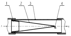
Fig. 1 is the structural representation of one-way flow SEALING FITTING described in the utility model.
Embodiment
Below for a more detailed description to the utility model by reference to the accompanying drawings with embodiment.Present embodiment only is the description to the utility model preferred forms, scope of the present utility model is not had any restriction.
Embodiment
As shown in Figure 1, be the structural representation of one-way flow SEALING FITTING described in the utility model.Described one-way flow SEALING FITTING comprises Taper Pipe 1, elasticity mouth 2, sleeve 3 and film 4, described elasticity mouth 2 is installed on the Taper Pipe 1, can adopt band or glue to fix, described Taper Pipe 1 is fixed on the inboard of sleeve 3, the two ends of described sleeve 3 are respectively arranged with A interface and B interface, and described film 4 is arranged on the end of elasticity mouth 2.Whole one-way flow SEALING FITTING can be connected with the pipeline at two ends with screw thread on the B interface by the A interface, also can use glue that A interface and B interface are bonded in the pipeline.
As shown in Figure 1, in use, when fluid (comprising gas and liquid) flows to B interface from the A interface, because the pressure effect of fluid, elasticity mouth 2 is expanded, elasticity mouth 2 ends will become circle gradually from flat like this, so fluid will arrive the B interface ends by film 4 back, thereby have realized circulation.
And when fluid flowed to the A interface from B interface, the pressure of fluid can more be pressed film 4 and elasticity mouth 2 more tight, thereby has stoped fluid to flow to the A interface from B interface, thereby has stoped circulation.
In sum, one-way flow SEALING FITTING described in the utility model can realize the one-way flow of liquid or gas easily, and simple in structure, and cost is lower.
Claims (2)
1. one-way flow SEALING FITTING, be used for the connection of pipeline, it is characterized in that: described one-way flow SEALING FITTING comprises Taper Pipe (1), elasticity mouth (2) and sleeve (3), described elasticity mouth (2) is installed on the Taper Pipe (1), described Taper Pipe (1) is fixed on the inboard of sleeve (3), and the two ends of described sleeve (3) are respectively arranged with A interface and B interface.
2. one-way flow SEALING FITTING according to claim 1, it is characterized in that: described one-way flow SEALING FITTING also comprises film (4), described film (4) is arranged on the end of elasticity mouth (2).
Priority Applications (1)
| Application Number | Priority Date | Filing Date | Title |
|---|---|---|---|
| CN 201320126107 CN203131266U (en) | 2013-03-20 | 2013-03-20 | Unidirectional-circulation sealing connector |
Applications Claiming Priority (1)
| Application Number | Priority Date | Filing Date | Title |
|---|---|---|---|
| CN 201320126107 CN203131266U (en) | 2013-03-20 | 2013-03-20 | Unidirectional-circulation sealing connector |
Publications (1)
| Publication Number | Publication Date |
|---|---|
| CN203131266U true CN203131266U (en) | 2013-08-14 |
Family
ID=48939244
Family Applications (1)
| Application Number | Title | Priority Date | Filing Date |
|---|---|---|---|
| CN 201320126107 Expired - Fee Related CN203131266U (en) | 2013-03-20 | 2013-03-20 | Unidirectional-circulation sealing connector |
Country Status (1)
| Country | Link |
|---|---|
| CN (1) | CN203131266U (en) |
Cited By (2)
| Publication number | Priority date | Publication date | Assignee | Title |
|---|---|---|---|---|
| CN112220979A (en) * | 2020-09-16 | 2021-01-15 | 上海市浦东医院(复旦大学附属浦东医院) | A special nursing device for nephrology |
| CN114877073A (en) * | 2022-03-28 | 2022-08-09 | 蔚来汽车科技(安徽)有限公司 | Seal structure, shock absorber and vehicle |
-
2013
- 2013-03-20 CN CN 201320126107 patent/CN203131266U/en not_active Expired - Fee Related
Cited By (2)
| Publication number | Priority date | Publication date | Assignee | Title |
|---|---|---|---|---|
| CN112220979A (en) * | 2020-09-16 | 2021-01-15 | 上海市浦东医院(复旦大学附属浦东医院) | A special nursing device for nephrology |
| CN114877073A (en) * | 2022-03-28 | 2022-08-09 | 蔚来汽车科技(安徽)有限公司 | Seal structure, shock absorber and vehicle |
Similar Documents
| Publication | Publication Date | Title |
|---|---|---|
| CN201141498Y (en) | Universal pipe and pipe connector | |
| CN204756244U (en) | Convenient type PVC arranges water piping connection structure | |
| CN201589425U (en) | Anti-rotation structure of water tank inlet and outlet pipes | |
| CN206881285U (en) | A kind of new water purifier | |
| CN210014121U (en) | Pipeline connecting structure of laundry machine | |
| CN216242823U (en) | Plug-in type control valve | |
| CN103486304A (en) | Rubber seal check valve | |
| CN205095527U (en) | Filter and water heater system | |
| CN205244493U (en) | Dish washer respirator check valve | |
| CN202972039U (en) | A float check valve and a hot and cold water mixing faucet | |
| CN209221659U (en) | Water flow control component, connection structure of water purification equipment and water purification equipment | |
| CN202852059U (en) | Energy-saving apparatus for mixing cold water with hot water | |
| CN201599441U (en) | Ball check valve | |
| CN204254100U (en) | Universal active joint | |
| CN207378236U (en) | A kind of Novel inserting connection type heating inlet valve | |
| CN207246627U (en) | A kind of quick pipe joint | |
| CN204962015U (en) | Installation structure of valve body and water purifier | |
| CN203929326U (en) | A kind of gasoline engine water pump test device for air tightness | |
| CN206988791U (en) | An identifier valve seat | |
| CN203718233U (en) | Three-way pipe | |
| CN216923519U (en) | External three-way valve assembly for zero-cold water heater | |
| CN201218377Y (en) | Drip irrigation system pipe quick connection device | |
| CN204533673U (en) | A kind of one-way valve | |
| CN204672001U (en) | A kind of y-type filter | |
| CN203742754U (en) | Novel water pipe connection structure of diesel engine |
Legal Events
| Date | Code | Title | Description |
|---|---|---|---|
| C14 | Grant of patent or utility model | ||
| GR01 | Patent grant | ||
| C17 | Cessation of patent right | ||
| CF01 | Termination of patent right due to non-payment of annual fee |
Granted publication date: 20130814 Termination date: 20140320 |