CN203125402U - Tool for mounting and dismounting round nut - Google Patents
Tool for mounting and dismounting round nut Download PDFInfo
- Publication number
- CN203125402U CN203125402U CN 201320021549 CN201320021549U CN203125402U CN 203125402 U CN203125402 U CN 203125402U CN 201320021549 CN201320021549 CN 201320021549 CN 201320021549 U CN201320021549 U CN 201320021549U CN 203125402 U CN203125402 U CN 203125402U
- Authority
- CN
- China
- Prior art keywords
- installing
- dismounting
- round nut
- round
- special tool
- Prior art date
- Legal status (The legal status is an assumption and is not a legal conclusion. Google has not performed a legal analysis and makes no representation as to the accuracy of the status listed.)
- Expired - Fee Related
Links
Images
Landscapes
- Hand Tools For Fitting Together And Separating, Or Other Hand Tools (AREA)
Abstract
Description
技术领域 technical field
本实用新型涉及一种螺母拆卸工具,尤其涉及用于压机上圆螺母的一种圆螺母安装拆卸专用工具。 The utility model relates to a nut removal tool, in particular to a special tool for installing and removing round nuts on a press machine.
背景技术 Background technique
在机械工厂,需要使用到许多的大型压力机,在压力机的结构上面有许多的圆螺母,圆螺母如图3所示,外形呈阶梯圆柱凸台状,包括大圆柱5和小圆柱6,小圆柱6设置在该大圆柱5上,在大圆柱5上形成环形的台阶面,该台阶面上制有多个盲孔。在设备维修的过程中,有时需要对圆螺母进行拆卸,圆螺母但是在对圆螺母进行拆卸的过程中,由于没有专用的拆卸扳手,只能利用铁锤以及冲头对螺母进行敲打,在螺母松动以后,才能将其拆卸,反之,在安装的时候也之只能采用此种方法才能件圆螺母零件拧紧,工作量大,其操作极为困难且浪费人力、物力以及需要很长的时间才能完成,且易将螺母损坏。 In the machinery factory, many large-scale presses need to be used. There are many round nuts on the structure of the press. The round nuts are shown in Figure 3. The shape is a stepped cylindrical boss, including a large cylinder 5 and a small cylinder 6. The small cylinder 6 is arranged on the large cylinder 5, and an annular stepped surface is formed on the large cylinder 5, and a plurality of blind holes are formed on the stepped surface. In the process of equipment maintenance, it is sometimes necessary to disassemble the round nut, but in the process of disassembling the round nut, since there is no special disassembly wrench, the nut can only be beaten with a hammer and a punch. After loosening, it can be disassembled. On the contrary, this method can only be used to tighten the round nut parts during installation. The workload is heavy, and the operation is extremely difficult and wastes manpower and material resources and takes a long time to complete. , and easy to damage the nut.
申请号为200920228818.3的中国专利公开了一种圆螺母,该圆螺母至少包括设有螺纹的内孔,圆螺母的外圆面呈阶梯状,由大圆柱面和小圆柱面连接组成,大圆柱面与小圆柱面间开有剖分槽,圆螺母的端面设有盲孔和螺钉孔。这种圆螺母同样难以拆卸。 The Chinese patent application number 200920228818.3 discloses a round nut. The round nut at least includes an inner hole provided with threads. A split groove is opened between the small cylindrical surface and a blind hole and a screw hole are arranged on the end surface of the round nut. Such round nuts are also difficult to remove.
发明内容 Contents of the invention
本实用新型主要是提供一种圆螺母安装拆卸专用工具,有效解决了拆卸、安装圆螺母时操作极为困难、耗时耗力、且易对圆螺母造成损坏等技术问题。 The utility model mainly provides a special tool for installing and dismounting round nuts, which effectively solves technical problems such as extremely difficult operation, time-consuming and labor-consuming, and easy damage to round nuts when disassembling and installing round nuts.
本实用新型的上述技术问题主要是通过下述技术方案得以解决的:它包括本体,所述本体的一端为手柄部,本体的另一端为端头部,所述端头部设有与圆螺母相配的圆孔状卡口,端头部的下端面设有若干直立的销头。本实用新型的端头部的卡口来套接圆螺母;本实用新型的销头的作用在于在对圆螺母进行拆卸时,销头存放入圆螺母上的孔内,使得圆螺母平均受力,而更方便的安装或是拆卸;使用时只需扳动手柄部即可。 The above-mentioned technical problems of the utility model are mainly solved by the following technical solutions: it includes a body, one end of the body is a handle portion, the other end of the body is a head portion, and the end portion is provided with a round nut The matching circular hole-shaped bayonet socket is provided with several upright pin heads on the lower surface of the end portion. The bayonet of the end of the utility model is used to socket the round nut; the function of the pin head of the utility model is that when the round nut is disassembled, the pin head is stored in the hole on the round nut, so that the round nut is evenly stressed , and more convenient to install or disassemble; only need to pull the handle when using.
作为优选,所述销头呈柱状,所述销头的轴心线与所述端头部的下端面垂直,所述销头的轴心线与所述卡口的轴心线平行。销头垂直于端头部的下端面,这样使得销头能更好的受力以及传递力。 Preferably, the pin head is columnar, the axis line of the pin head is perpendicular to the lower end surface of the end portion, and the axis line of the pin head is parallel to the axis line of the bayonet socket. The pin head is perpendicular to the lower end surface of the end portion, so that the pin head can better bear force and transmit force. the
作为优选,所述销头环绕所述卡口均布在所述端头部的下端面。销头平均分布于端头部的下端面,其位置正好与圆螺母上的孔对应,有利于本实用新型与圆螺母紧密结合。 Preferably, the pin heads are evenly distributed on the lower end surface of the end portion around the bayonet socket. The pin heads are evenly distributed on the lower end surface of the end portion, and its position just corresponds to the hole on the round nut, which is conducive to the close combination of the utility model and the round nut. the
作为优选,所述销头的截面为圆形或多边形。 Preferably, the cross section of the pin head is circular or polygonal. the
作为优选,所述端头部为平板状,端头部的轴心线与所述卡口的轴心线重合。为了适应更小的操作空间,本实用新型将端头部设置成平板状。 Preferably, the end portion is flat, and the axis of the end portion coincides with the axis of the bayonet socket. In order to adapt to a smaller operating space, the utility model sets the end portion into a flat plate shape.
作为优选,所述销头设置有三个。销头数量一般和压机圆螺母台阶面的孔的数量相对应,只可以比圆螺母上的孔数少,不能多,设置三个销头,可以使圆螺母上的力分布更均匀,以保护圆螺母不受损伤。 Preferably, there are three pin heads. The number of pin heads generally corresponds to the number of holes on the step surface of the round nut of the press. It can only be less than the number of holes on the round nut, but not more. Setting three pin heads can make the force distribution on the round nut more uniform, so that Protect round nuts from damage. the
作为优选,所述手柄部设有加长杆。当螺母连接较紧,难以直接扳开或者需要螺母更紧固时,可以增加加长杆,利用杠杆原理,起到加力作用。 Preferably, the handle part is provided with an extension rod. When the nut is tightly connected and it is difficult to pull it apart directly or when the nut needs to be tightened more tightly, an extension rod can be added to use the principle of leverage to increase the force. the
作为优选,所述加长杆为圆筒状。这样只需将加长杆套接在手柄部端头即可。 Preferably, the extension rod is cylindrical. In this way, it is only necessary to sleeve the extension rod on the end of the handle part. the
作为优选,所述卡口与圆螺母间隙配合,卡口内径比相应的圆螺母直径大0-5mm。使用时便于本实用新型转动,不会发生干涉。 Preferably, the bayonet fits with the round nut in a clearance, and the inner diameter of the bayonet is 0-5mm larger than the diameter of the corresponding round nut. When in use, the utility model is convenient to rotate without interference.
本实用新型带来的有益效果是,本实用新型结构简单合理,加工方便,使用时方便快捷,缩短了安装、拆卸圆螺母的时间,减轻了员工的劳动强度,并且结构稳固,防止了圆螺母的损坏。 The beneficial effects brought by the utility model are that the utility model is simple and reasonable in structure, easy to process, convenient and quick to use, shortens the time for installing and disassembling the round nut, reduces the labor intensity of employees, and has a stable structure, which prevents the round nut from damage.
附图说明 Description of drawings
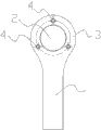
附图1是本实用新型的一种结构示意图; Accompanying drawing 1 is a kind of structural representation of the utility model;
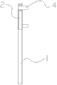
附图2是附图1的一种剖视结构示意图;
附图3是现有技术中圆螺母的一种结构示意图。 Accompanying drawing 3 is a kind of structure diagram of round nut in the prior art.
标号说明:1、手柄部;2、卡口;3、端头部;4、销头;5、大圆柱;6、小圆柱。 Explanation of symbols: 1. handle part; 2. bayonet socket; 3. end part; 4. pin head; 5. large cylinder; 6. small cylinder.
具体实施方式 Detailed ways
下面通过实施例,并结合附图,对本实用新型的技术方案作进一步具体的说明。 The technical solutions of the present utility model will be further specifically described below through the embodiments and in conjunction with the accompanying drawings.
实施例:本实施例的一种圆螺母安装拆卸专用工具,如图1、2所示,包括本体,本体的一端为手柄部1,手柄部1套接有圆筒状加长杆,本体的另一端为端头部3。 Embodiment: A special tool for installation and disassembly of round nuts in this embodiment, as shown in Figures 1 and 2, includes a body, one end of the body is a handle part 1, and the handle part 1 is sleeved with a cylindrical extension rod. One end is a terminal head 3 .
端头部3为平板状,端头部3设有与圆螺母相配的圆孔状卡口2,端头部3的轴心线与卡口2的轴心线重合,卡口2可与圆螺母间隙配合,卡口2内径比相应的圆螺母直径大0-5mm,端头部3的下端面安装有三个直立的销头4。
The end portion 3 is flat, and the end portion 3 is provided with a round hole-
销头4呈柱状,销头4的截面为圆形,各销头4环绕卡口2均布在所述端头部3的下端面,销头4的轴心线与端头部3的下端面垂直,销头4的轴心线与卡口2的轴心线平行。
The
以上仅就本实用新型较佳的实施例作了说明,但不能理解为是对本实用新型保护范围的限制。本实用新型不仅局限于以上实施例,其具体结构或形状允许有变化。总之,本实用新型的保护范围应包括那些对应本领域普通技术人员来说显而易见的变换或者替代以及改型。 The above is only a description of the preferred embodiments of the utility model, but it should not be understood as a limitation to the protection scope of the utility model. The utility model is not limited to the above embodiments, and its specific structure or shape is allowed to be changed. In a word, the protection scope of the present utility model shall include those transformations or substitutions and modifications that are obvious to those skilled in the art.
Claims (9)
Priority Applications (1)
| Application Number | Priority Date | Filing Date | Title |
|---|---|---|---|
| CN 201320021549 CN203125402U (en) | 2013-01-16 | 2013-01-16 | Tool for mounting and dismounting round nut |
Applications Claiming Priority (1)
| Application Number | Priority Date | Filing Date | Title |
|---|---|---|---|
| CN 201320021549 CN203125402U (en) | 2013-01-16 | 2013-01-16 | Tool for mounting and dismounting round nut |
Publications (1)
| Publication Number | Publication Date |
|---|---|
| CN203125402U true CN203125402U (en) | 2013-08-14 |
Family
ID=48933422
Family Applications (1)
| Application Number | Title | Priority Date | Filing Date |
|---|---|---|---|
| CN 201320021549 Expired - Fee Related CN203125402U (en) | 2013-01-16 | 2013-01-16 | Tool for mounting and dismounting round nut |
Country Status (1)
| Country | Link |
|---|---|
| CN (1) | CN203125402U (en) |
Cited By (1)
| Publication number | Priority date | Publication date | Assignee | Title |
|---|---|---|---|---|
| CN108214374A (en) * | 2017-12-19 | 2018-06-29 | 龙口矿业集团有限公司 | A kind of high pressure sluice valve switchs power-assisted wrench |
-
2013
- 2013-01-16 CN CN 201320021549 patent/CN203125402U/en not_active Expired - Fee Related
Cited By (1)
| Publication number | Priority date | Publication date | Assignee | Title |
|---|---|---|---|---|
| CN108214374A (en) * | 2017-12-19 | 2018-06-29 | 龙口矿业集团有限公司 | A kind of high pressure sluice valve switchs power-assisted wrench |
Similar Documents
| Publication | Publication Date | Title |
|---|---|---|
| CN201030538Y (en) | A bearing removal device | |
| CN204263073U (en) | A kind of bushing dismounting instrument | |
| CN201082532Y (en) | A shaft sleeve removal device | |
| CN203330967U (en) | Bearing disassembling device | |
| CN202607600U (en) | Bolt detaching equipment | |
| CN205572275U (en) | A dismouting device that is used for bolt elongator pull head assembly | |
| CN206200882U (en) | For the specific purpose tool of vehicle motor wet cylinder liner dismounting | |
| CN204525346U (en) | Novel pin remover | |
| CN105071294A (en) | Ratchet wrench for high-voltage power transmission line | |
| CN201244801Y (en) | Bolt detacher | |
| CN105082026B (en) | Hexagon socket head cap screw fast dismounting device | |
| CN203438175U (en) | Detaching and installing tool for round nut at concaved position | |
| CN211163717U (en) | Special assembly and disassembly tools of production tree well head screw | |
| CN204221340U (en) | A kind of hollow bolt tool special for dismounting | |
| CN204640065U (en) | A kind of bull Ratchel type wrench | |
| CN204585145U (en) | Reductor dismantling device | |
| CN105563421B (en) | A kind of special screw stripping attachment | |
| CN204036335U (en) | Pumping unit crank pin removal tool | |
| CN204886006U (en) | A ratchet spanner for high tension transmission line | |
| CN204136007U (en) | The valve seat tool for assembling of valve | |
| CN203062690U (en) | Simple pin installing and pulling device | |
| CN202399216U (en) | Demounting device for large-sized hub bearings of traction motor | |
| CN209190631U (en) | Spanner | |
| CN105257662A (en) | Demounting-proof nut and matched special tool thereof | |
| CN201192832Y (en) | Construction Vehicle Caliper Disc Brake Piston Removal Tool |
Legal Events
| Date | Code | Title | Description |
|---|---|---|---|
| C14 | Grant of patent or utility model | ||
| GR01 | Patent grant | ||
| C17 | Cessation of patent right | ||
| CF01 | Termination of patent right due to non-payment of annual fee |
Granted publication date: 20130814 Termination date: 20140116 |