CN203092785U - Machining device of spherical stone - Google Patents
Machining device of spherical stone Download PDFInfo
- Publication number
- CN203092785U CN203092785U CN 201320062499 CN201320062499U CN203092785U CN 203092785 U CN203092785 U CN 203092785U CN 201320062499 CN201320062499 CN 201320062499 CN 201320062499 U CN201320062499 U CN 201320062499U CN 203092785 U CN203092785 U CN 203092785U
- Authority
- CN
- China
- Prior art keywords
- base
- slide
- main shaft
- moving mechanism
- screw mandrel
- Prior art date
- Legal status (The legal status is an assumption and is not a legal conclusion. Google has not performed a legal analysis and makes no representation as to the accuracy of the status listed.)
- Expired - Fee Related
Links
- 239000004575 stone Substances 0.000 title claims abstract description 18
- 238000003754 machining Methods 0.000 title abstract description 3
- 238000005520 cutting process Methods 0.000 claims abstract description 8
- 238000000926 separation method Methods 0.000 claims description 3
- 239000000463 material Substances 0.000 description 9
- 238000000034 method Methods 0.000 description 5
- 230000004888 barrier function Effects 0.000 description 2
- 230000009286 beneficial effect Effects 0.000 description 1
- 230000007812 deficiency Effects 0.000 description 1
- 238000005516 engineering process Methods 0.000 description 1
Images
Landscapes
- Processing Of Stones Or Stones Resemblance Materials (AREA)
Abstract
A machining device for spherical stone comprises a base, a workpiece clamping device arranged on the base, a first sliding base, a second sliding base, a main shaft, a main motor, a plurality of circular saw webs, a longitudinally-moving mechanism and a transversely-moving mechanism. The first sliding base can be arranged on the base in a horizontally moving mode in the longitudinal direction. The second sliding base can be arranged on the first sliding base in a horizontally moving mode in the transverse direction. The main shaft is transversely and horizontally arranged on the second sliding base. The main shaft is connected with the main shaft and drives the main shaft to rotate. The circular saw webs are arranged on the main shaft. The longitudinally-moving mechanism is arranged between the first sliding base and the base. The transversely-moving mechanism is arranged between the first sliding base and the second sliding base. The workpiece clamping device comprises a head frame and a tail frame which are transversely arranged at intervals. The head frame and the tail frame are respectively provided with a tip shaft which is transversely and horizontally arranged. The head frame is provided with a motor which is connected with the tip shaft of the head frame and drives the tip shaft to rotate. The tail frame can be arranged on the base and can move and be adjusted in the transverse direction. The circular saw webs on the main shaft can be arrayed according to sizes of the diameters so as to form an arc-shaped cutting outer edge.
Description
Technical field
The utility model relates to a kind of spherical stones processing appts.
Background technology
Existing spherical stone material adopts barrier machine to process usually, because the processing saw blade of barrier machine has only one, long processing time, efficient are low, can't meet the need of market.
Summary of the invention
The purpose of this utility model is at the deficiencies in the prior art, but the processing unit (plant) of the spherical stone material of a kind of highly-efficient processing is provided.
The purpose of this utility model realizes by following technical solution:
A kind of spherical stones processing appts, it is characterized in that: comprise base, be arranged at the work holder on the base, can be arranged at first slide on the base with longitudinally moving horizontally, can be arranged at second slide on first slide movably along transverse horizontal, transverse horizontal is arranged in the main shaft that is arranged on second slide, connect the main motor that drive shaft is rotated, be arranged at a plurality of saw blades on the main shaft, be arranged at the longitudinal moving mechanism between first slide and the base and be arranged at first, transverse moving mechanism between second slide, described work holder comprises the headstock and the tailstock that the lateral separation is arranged, the headstock and tailstock are respectively arranged with the tail spindle that transverse horizontal is arranged, the headstock is provided with to connect and drives the motor that tail spindle rotates, tailstock can be arranged on the base along laterally moving with adjusting, and a plurality of saw blades on the main shaft are arranged to form the cutting outer of circular arc according to diameter.
Further, described longitudinal moving mechanism comprise longitudinally horizontally disposed on base first screw mandrel, be arranged at the nut that matches with first screw mandrel on first slide and be connected and drive first motor that first screw mandrel rotates.
Further, described transverse moving mechanism comprises along transverse horizontal and is arranged in second screw mandrel on first slide, is arranged at the nut that matches with second screw mandrel on second slide and is connected and drive second motor that second screw mandrel rotates.
The utlity model has following beneficial effect:
A plurality of saw blades and saw blade are set on main shaft to be arranged to form the cutting outer of circular arc according to diameter, the cutting outer that adds circular arc in man-hour can cut out arc-shaped surface on stone material, cooperate work holder to drive the stone material rotation and then can process spherical stone material, a plurality of saw blades are set process simultaneously and can improve working (machining) efficiency of the present utility model greatly.
Description of drawings
Below in conjunction with accompanying drawing the utility model is described in further detail.
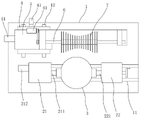
Fig. 1 is a structural representation of the present utility model, depression angle.
The specific embodiment
With reference to shown in Figure 1, a kind of spherical stones processing appts, comprise base 1, be arranged at the work holder on the base 1, can be arranged at first slide 4 on the base 1 with longitudinally moving horizontally, can be arranged at second slide 5 on first slide 4 movably along transverse horizontal, transverse horizontal is arranged in the main shaft 6 that is arranged on second slide 5, be connected the main motor 61 that drive shaft 6 is rotated with belt by belt pulley, be arranged at a plurality of saw blades 7 on the main shaft 6, be arranged at the longitudinal moving mechanism between first slide 4 and the base 1 and be arranged at first, second slide 4, transverse moving mechanism between 5, first slide 4 is arranged on the base 1 movably by the guide rail 12 that is arranged at base 1 upper edge vertical equity extension, second slide 5 is arranged on first slide 4 movably by the guide rail (not shown) that is arranged at the 4 upper edge transverse horizontal extensions of first slide, and a plurality of saw blades 7 on the main shaft 6 are arranged to form the cutting outer of circular arc according to diameter.
Work holder comprises the headstock 21 and the tailstock 22 that the lateral separation is arranged, the headstock 21 and tailstock 22 are respectively arranged with the tail spindle 211,221 that transverse horizontal is arranged, the headstock 21 is provided with to connect and drives the motor 212 that tail spindle 211 rotates, tailstock 22 can be arranged on the base 1 along laterally moving with adjusting, concrete base 1 is provided with the guide rail 11 that transverse horizontal is extended, and tailstock 22 is movably set on the guide rail 11.
Longitudinal moving mechanism comprise longitudinally horizontally disposed on base 1 the first screw mandrel (not shown), be arranged at the nut (not shown) that matches with first screw mandrel on first slide 4 and be connected and drive first motor 41 that first screw mandrel rotates; Transverse moving mechanism comprises along transverse horizontal and is arranged in the second screw mandrel (not shown) on first slide 4, is arranged at the nut (not shown) that matches with second screw mandrel on second slide 5 and is connected and drive second motor 51 that second screw mandrel rotates.
Concrete working method is: in advance stone material to be processed 3 is clamped between the headstock 21 and tailstock 22 tail spindles 211,221, motor 212 drives tail spindle and rotates 3 rotations of drive stone material, main motor 61 drive shaft 6 are rotated to drive a plurality of saw blade 7 rotation cuttings, move according to default track by longitudinal moving mechanism and laterally mobile driving saw blade 7, cut stone material 3 the circular arc cutting outer that a plurality of saw blades 7 form, thereby process spherical stone material.
The above, it only is preferred embodiment of the present utility model, so can not limit the scope that the utility model is implemented with this, i.e. the equivalence of doing according to the utility model claim and description changes and modifies, and all should still belong in the scope that the utility model patent contains.
Claims (3)
1. spherical stones processing appts, it is characterized in that: comprise base, be arranged at the work holder on the base, can be arranged at first slide on the base with longitudinally moving horizontally, can be arranged at second slide on first slide movably along transverse horizontal, transverse horizontal is arranged in the main shaft that is arranged on second slide, connect the main motor that drive shaft is rotated, be arranged at a plurality of saw blades on the main shaft, be arranged at the longitudinal moving mechanism between first slide and the base and be arranged at first, transverse moving mechanism between second slide, described work holder comprises the headstock and the tailstock that the lateral separation is arranged, the headstock and tailstock are respectively arranged with the tail spindle that transverse horizontal is arranged, the headstock is provided with to connect and drives the motor that tail spindle rotates, tailstock can be arranged on the base along laterally moving with adjusting, and a plurality of saw blades on the main shaft are arranged to form the cutting outer of circular arc according to diameter.
2. a kind of spherical stones processing appts according to claim 1 is characterized in that: described longitudinal moving mechanism comprise longitudinally horizontally disposed on base first screw mandrel, be arranged at the nut that matches with first screw mandrel on first slide and be connected and drive first motor that first screw mandrel rotates.
3. a kind of spherical stones processing appts according to claim 1 is characterized in that: described transverse moving mechanism comprises along transverse horizontal and is arranged in second screw mandrel on first slide, is arranged at the nut that matches with second screw mandrel on second slide and is connected and drive second motor that second screw mandrel rotates.
Priority Applications (1)
| Application Number | Priority Date | Filing Date | Title |
|---|---|---|---|
| CN 201320062499 CN203092785U (en) | 2013-01-31 | 2013-01-31 | Machining device of spherical stone |
Applications Claiming Priority (1)
| Application Number | Priority Date | Filing Date | Title |
|---|---|---|---|
| CN 201320062499 CN203092785U (en) | 2013-01-31 | 2013-01-31 | Machining device of spherical stone |
Publications (1)
| Publication Number | Publication Date |
|---|---|
| CN203092785U true CN203092785U (en) | 2013-07-31 |
Family
ID=48844224
Family Applications (1)
| Application Number | Title | Priority Date | Filing Date |
|---|---|---|---|
| CN 201320062499 Expired - Fee Related CN203092785U (en) | 2013-01-31 | 2013-01-31 | Machining device of spherical stone |
Country Status (1)
| Country | Link |
|---|---|
| CN (1) | CN203092785U (en) |
Cited By (1)
| Publication number | Priority date | Publication date | Assignee | Title |
|---|---|---|---|---|
| CN103612334A (en) * | 2013-11-30 | 2014-03-05 | 陆荣茂 | Stone material saw |
-
2013
- 2013-01-31 CN CN 201320062499 patent/CN203092785U/en not_active Expired - Fee Related
Cited By (1)
| Publication number | Priority date | Publication date | Assignee | Title |
|---|---|---|---|---|
| CN103612334A (en) * | 2013-11-30 | 2014-03-05 | 陆荣茂 | Stone material saw |
Similar Documents
| Publication | Publication Date | Title |
|---|---|---|
| CN203221244U (en) | Multi-angle double-cutting circular sawing machine | |
| CN103203808B (en) | Efficient multi-line cutting device and method | |
| CN207888334U (en) | A planer knife grinder | |
| CN204975460U (en) | Wheel hub milling machine | |
| CN102794665A (en) | Feeding mechanism for desktop electric circular sawing machines | |
| CN207479736U (en) | Pipe fitting sawing circular saw bench | |
| CN202447675U (en) | Single spindle bidirectional cutting numerical control lathe | |
| CN204367198U (en) | Multi-thread broken side's cutting machine | |
| CN205651057U (en) | Rough machining forming device of large module gear | |
| CN209035625U (en) | A kind of curved-tooth bevel gear radiusing machine | |
| CN103934504B (en) | A kind of special band sawing machine of drum shaft inclined-plane sawing and using method thereof | |
| CN109175544A (en) | A kind of curved-tooth bevel gear radiusing machine | |
| CN203380718U (en) | Numerical control cutting and grinding machine for slot wedges | |
| CN204397404U (en) | A kind of cutting machine cushion cap | |
| CN203751919U (en) | Automatic steel pipe polishing machine | |
| CN203357683U (en) | Spherical stone cutter | |
| CN203236307U (en) | Grooving machining device | |
| CN203092784U (en) | Stone railing machine | |
| CN104493985A (en) | Stone line molding machine capable of forming angle grooves | |
| CN203600323U (en) | PVC pipe chipless cutting machine with chamfering function | |
| CN103350345A (en) | Numerical control cutting mill for slot wedge | |
| CN202804786U (en) | Feeding mechanism of table type electric circular sawing machine | |
| CN202155620U (en) | Device for machining external thread on hard alloy material | |
| CN201471002U (en) | A vertical metal band sawing machine | |
| CN204382507U (en) | A kind of can the stone material mo(u)lding machine of machining angle groove |
Legal Events
| Date | Code | Title | Description |
|---|---|---|---|
| C14 | Grant of patent or utility model | ||
| GR01 | Patent grant | ||
| CF01 | Termination of patent right due to non-payment of annual fee | ||
| CF01 | Termination of patent right due to non-payment of annual fee |
Granted publication date: 20130731 Termination date: 20180131 |