CN203076421U - Automatic side punching die for multi-station forming machine - Google Patents
Automatic side punching die for multi-station forming machine Download PDFInfo
- Publication number
- CN203076421U CN203076421U CN 201320112255 CN201320112255U CN203076421U CN 203076421 U CN203076421 U CN 203076421U CN 201320112255 CN201320112255 CN 201320112255 CN 201320112255 U CN201320112255 U CN 201320112255U CN 203076421 U CN203076421 U CN 203076421U
- Authority
- CN
- China
- Prior art keywords
- cylindrical hole
- sliding block
- positioning sliding
- punching
- slider
- Prior art date
- Legal status (The legal status is an assumption and is not a legal conclusion. Google has not performed a legal analysis and makes no representation as to the accuracy of the status listed.)
- Withdrawn - After Issue
Links
Images


Abstract
The utility model discloses an automatic side punching die for a multi-station forming machine, comprising a punch, a concave die and a locating slider, wherein a reserved part mounting groove is formed on the upper end surface of the locating slider, the inner cavity of the concave die comprises a cylindrical hole, a truncated cone shaped counterbore arranged at the upper end of the cylindrical hole, and a cylindrical counterbore arranged at the lower end of the cylindrical hole, the locating slider is arranged in the inner cavity of the concave die, the outer edge of the bottom of the locating slider is protruded and pushes against a transitional step surface between the cylindrical hole and the cylindrical counterbore, a punching slider is also arranged above the locating slider and is distributed at the peripheral edge of the reserved part mounting groove, the back part of the punching slider is closely attached to the inner surface of the truncated cone shaped counterbore, and a pressing block which can push the punching slider to move downwards along the inner surface of the truncated cone shaped counterbore when the punch presses the locating slider is also sheathed on the punch. The automatic side punching die for the multi-station forming machine can be well matched with the multi-station forming machine, and can realize side punching to a stretching part on the multi-station forming machine.
Description
Technical field
The utility model relates to a kind of automatic side of cooperation mould, particularly multistation machine perforating mold of multistation machine.
Background technology
Drawing and forming is used punching press exactly, and the technology of draw ring or metal pattern is the plate-type metal material deformation part of cylinder or box-shape on multistation stretching punch press.
Stretching technique is used very extensive in process of production, is applied to a lot of industries.For example, can be used in and produce auto parts in the automobile industry; Can also be used to making household products, for example the stainless steel kitchen scullery basin.While is along with the extensive use of stretching technique, the structure of tensioning member and shape are also more and more diversified, the tensioning member that a kind of sidewall need punch has appearred at present, traditional production method is exactly to punch taking on the automatic punch in addition by the tensioning member after the multistation machine moulding, the production efficiency of the above-mentioned mode of production is low, and product has the situation of mobile station in forming process, makes that the punching accuracy that finally obtains product is not high, influence product quality and concrete serviceability.
The utility model content
The purpose of this utility model is to provide a kind of in order to solve above-mentioned the deficiencies in the prior art can cooperate with the multistation automatic punching machine, tensioning member is realized the automatic side of the multistation machine perforating mold of side punching.
To achieve these goals, the automatic side of the multistation machine perforating mold that the utility model is designed, comprise jumper bar, die and positioning sliding block, be provided with reservation part mounting groove in the upper surface of positioning sliding block, the inner chamber of described die comprises cylindrical hole and is positioned at the truncated cone-shaped reaming of cylindrical hole upper end and is positioned at the cylindricality reaming of cylindrical hole lower end, positioning sliding block is arranged in the inner chamber of above-mentioned die, and the bottom outer rim projection of positioning sliding block and the transition bench terrace apical grafting between cylindrical hole and the cylindricality reaming, above positioning sliding block, also be provided with the punching slide block, and the punching slide block is distributed in the neighboring of reserving the part mounting groove, the inner surface of truncated cone-shaped reaming is close at the back of the slide block of punching simultaneously, when jumper bar presses down positioning sliding block, can promote the punching slide block and complying with the compact heap that the inner surface of truncated cone-shaped reaming moves downward also being socketed with on the jumper bar, on jumper bar, also be provided with the default through hole that cooperates with the punching slide block.
For convenience on the die sidewall, spacer pin is installed, also is provided with the limiting through hole that connects with cylindrical hole on the sidewall of die described in the utility model.Spacer pin is installed in above-mentioned limiting through hole can be carried out spacingly, prevent from when work, to bump between the positioning sliding block and manipulator positioning sliding block.
The automatic side of the multistation machine that the utility model obtains perforating mold, its cooperation mould as multistation machine uses, make tensioning member can on multistation machine, just realize the technology of sidewall punching, to take on the automatic punch in addition by the tensioning member after the multistation machine moulding in the traditional handicraft of comparing and punch, it is higher that the sidewall that cooperates the perforating mold that provides in the utility model to obtain by multistation machine carries out its precision of tensioning member that drilling technology handles, production efficiency is better, can also promote the business economic benefit for enterprise saves the manpower expenditure simultaneously.
Description of drawings
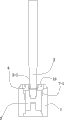
Fig. 1 is the structural representation of embodiment 1;
Fig. 2 is the structural representation of die among the embodiment 1;
Fig. 3 is the structural representation of punching slide block among the embodiment 1;
Fig. 4 is the structural representation of D positioning sliding block among the embodiment 1;
Fig. 5 is that embodiment 1 is at the partial structurtes schematic diagram that specifically is installed on the multistation machine;
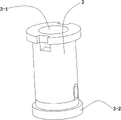
Fig. 6 is the structural representation of embodiment 2.
Among the figure: die 1, jumper bar 2, reservation through hole 2-1, positioning sliding block 3, reservation part mounting groove 3-1 outer rim projection 3-2, punching slide block 4, cylindrical hole 5, cylindricality reaming 6, truncated cone-shaped reaming 7, the inner surface 7-1 of truncated cone-shaped reaming, limiting through hole 8, upper table 9, lower table 10, jumping core 11, transition bench terrace 12, compact heap 13, back-moving spring 14.
The specific embodiment
Below in conjunction with drawings and Examples the utility model is further specified.
Embodiment 1:
At Fig. 1, Fig. 2, Fig. 3 and shown in Figure 4, the automatic side of the multistation machine that present embodiment provides perforating mold, comprise jumper bar 2, die 1 and positioning sliding block 3, be provided with reservation part mounting groove 3-1 in the upper surface of positioning sliding block 3, truncated cone-shaped reaming 7 and the cylindricality reaming 6 that is positioned at cylindrical hole 5 lower ends that the inner chamber of described die 1 comprises cylindrical hole 5 and is positioned at cylindrical hole 5 upper ends, positioning sliding block 3 is arranged in the inner chamber of above-mentioned die 1, and the bottom outer rim projection 3-2 of positioning sliding block 3 and transition bench terrace 12 apical graftings between cylindrical hole 5 and the cylindricality reaming 6, above positioning sliding block 3, also be provided with punching slide block 4, and punching slide block 4 is distributed in the neighboring of reserving part mounting groove 3-1, the inner surface 7-1 of truncated cone-shaped reaming is close at the back of the slide block of punching simultaneously 4, when jumper bar 2 presses down positioning sliding block 3, can promote punching slide block 4 and complying with the compact heap 13 that the inner surface 7-1 of truncated cone-shaped reaming moves downward also being socketed with on the jumper bar 2, on jumper bar 2, also be provided with the default limiting through hole 2-1 that cooperates with punching slide block 4.
As shown in Figure 5, when cooperating multistation machine specifically to use, jumper bar 2 is fixed on the upper table 9 of multistation machine, die 1 is fixed on the lower table 10 of multistation machine, and the positioning sliding block 3 in the 11 aligning dies 1 of the jumping core on the lower table 10.Its concrete course of work is as follows: upper table 9 drives jumper bar 2 and makes impulsion work down, the end of jumper bar 2 enters in the reservation part mounting groove 3-1 of positioning sliding block 3, jumper bar 2 continues to do impulsion down and does, promote positioning sliding block 3 and vertically down produce the tiltedly down operation of inner surface 7-1 that displacement and punching slide block 4 are being complied with the truncated cone-shaped reaming, until contact and run through the part sidewall of reserving in the part mounting groove 3-1; After above-mentioned work step was finished, upper table 9 drove the action that jumper bar 2 up withdraws from die 1, and positioning sliding block 3 in the die 1 and punching slide block 4 are also finished under the effect of back-moving spring 14 below the jumping core 11 and resetted simultaneously.
Embodiment 2:
As shown in Figure 6, the automatic side of the multistation machine that present embodiment provides perforating mold, its general structure is consistent with embodiment 1, but on die 1 sidewall, spacer pin is installed for convenience, also be provided with the limiting through hole 8 that connects with cylindrical hole 5 on 1 sidewall of die described in the present embodiment, above-mentioned limiting through hole 8 preferred waist-shaped holes.Spacer pin is installed in above-mentioned limiting through hole 8 can be carried out spacingly, prevent from when work, to bump between the positioning sliding block 3 and manipulator positioning sliding block 3.
Claims (2)
1. the automatic side of multistation machine perforating mold, comprise jumper bar (2), die (1) and positioning sliding block (3), be provided with reservation part mounting groove (3-1) in the upper surface of positioning sliding block (3), it is characterized in that: the inner chamber of described die (1) comprises cylindrical hole (5) and is positioned at the truncated cone-shaped reaming (7) of cylindrical hole (5) upper end and is positioned at the cylindricality reaming (6) of cylindrical hole (5) lower end, positioning sliding block (3) is arranged in the inner chamber of above-mentioned die (1), and transition bench terrace (12) apical grafting between the bottom outer rim projection (3-2) of positioning sliding block (3) and cylindrical hole (5) and the cylindricality reaming (6), also be provided with punching slide block (4) in the top of positioning sliding block (3), and punching slide block (4) is distributed in the neighboring of reserving part mounting groove (3-1), the inner surface (7-1) of truncated cone-shaped reaming is close at the back of punching slide block (4) simultaneously, when jumper bar (2) presses down positioning sliding block (3), can promote punching slide block (4) and complying with the compact heap (13) that the inner surface (7-1) of truncated cone-shaped reaming moves downward also being socketed with on the jumper bar (2), on jumper bar (2), also be provided with the default through hole (2-1) that cooperates with punching slide block (4).
2. the automatic side of multistation machine according to claim 1 perforating mold is characterized in that: also be provided with the limiting through hole (8) that connects with cylindrical hole (5) on described die (1) sidewall.
Priority Applications (1)
| Application Number | Priority Date | Filing Date | Title |
|---|---|---|---|
| CN 201320112255 CN203076421U (en) | 2013-03-13 | 2013-03-13 | Automatic side punching die for multi-station forming machine |
Applications Claiming Priority (1)
| Application Number | Priority Date | Filing Date | Title |
|---|---|---|---|
| CN 201320112255 CN203076421U (en) | 2013-03-13 | 2013-03-13 | Automatic side punching die for multi-station forming machine |
Publications (1)
| Publication Number | Publication Date |
|---|---|
| CN203076421U true CN203076421U (en) | 2013-07-24 |
Family
ID=48822299
Family Applications (1)
| Application Number | Title | Priority Date | Filing Date |
|---|---|---|---|
| CN 201320112255 Withdrawn - After Issue CN203076421U (en) | 2013-03-13 | 2013-03-13 | Automatic side punching die for multi-station forming machine |
Country Status (1)
| Country | Link |
|---|---|
| CN (1) | CN203076421U (en) |
Cited By (2)
| Publication number | Priority date | Publication date | Assignee | Title |
|---|---|---|---|---|
| CN103203408A (en) * | 2013-03-13 | 2013-07-17 | 慈溪市天时机械有限公司 | Automatic lateral face punching mould of multi-station molding machine |
| WO2017113410A1 (en) * | 2015-12-31 | 2017-07-06 | 深圳市大富精工有限公司 | Apparatus and method for punching side slot of usb metal housing |
-
2013
- 2013-03-13 CN CN 201320112255 patent/CN203076421U/en not_active Withdrawn - After Issue
Cited By (2)
| Publication number | Priority date | Publication date | Assignee | Title |
|---|---|---|---|---|
| CN103203408A (en) * | 2013-03-13 | 2013-07-17 | 慈溪市天时机械有限公司 | Automatic lateral face punching mould of multi-station molding machine |
| WO2017113410A1 (en) * | 2015-12-31 | 2017-07-06 | 深圳市大富精工有限公司 | Apparatus and method for punching side slot of usb metal housing |
Similar Documents
| Publication | Publication Date | Title |
|---|---|---|
| CN201880798U (en) | Blanking, punching and shaping composite stamping die | |
| CN202062004U (en) | Novel precise stamping die | |
| CN102327952B (en) | Floating matrix trimming piercing die | |
| CN103084488B (en) | Two-way blank pressing drawing and coining integration die | |
| CN203853457U (en) | Material ejection type material falling punching composite mold | |
| CN204308042U (en) | A kind of compound progressive die | |
| CN202291045U (en) | Compound die for trimming and punching | |
| CN203565673U (en) | Bearing base die | |
| CN202263833U (en) | Trimming and piercing die for floating cavity die | |
| CN203076421U (en) | Automatic side punching die for multi-station forming machine | |
| CN206567395U (en) | A kind of side piercing die of automobile engine reinforcer | |
| CN206286415U (en) | Drawing progressive die for processing flanged pin cylindrical part | |
| CN203091543U (en) | Deep-drawing and coining integrated die capable of carrying out bidirectional side pressing | |
| CN103418676B (en) | Vehicle door plate punching hole flanging method | |
| CN102962345A (en) | Punching, blanking and stretching die for take-or-pay table | |
| CN204638892U (en) | The drawing die of cylindrical shape sheet metal component | |
| CN202825949U (en) | Press-fit double-punching die | |
| CN202825948U (en) | Press-fit punching die | |
| CN208019284U (en) | A kind of automatic punching die of thin-walled annular workpiece | |
| CN103203408A (en) | Automatic lateral face punching mould of multi-station molding machine | |
| CN201768823U (en) | Mould for forming stamping part of bimetallic bracket | |
| CN202045269U (en) | Footstep extruding die for bearing shim | |
| CN205128732U (en) | Circular connection tray blanking compound die that punches a hole | |
| CN204974966U (en) | Part forming die | |
| CN203791468U (en) | Lower edge folding and stretching die structure |
Legal Events
| Date | Code | Title | Description |
|---|---|---|---|
| C14 | Grant of patent or utility model | ||
| GR01 | Patent grant | ||
| AV01 | Patent right actively abandoned |
Granted publication date: 20130724 Effective date of abandoning: 20150401 |
|
| RGAV | Abandon patent right to avoid regrant |