CN203051051U - Novel valve sheet of air compressor - Google Patents
Novel valve sheet of air compressor Download PDFInfo
- Publication number
- CN203051051U CN203051051U CN 201320183037 CN201320183037U CN203051051U CN 203051051 U CN203051051 U CN 203051051U CN 201320183037 CN201320183037 CN 201320183037 CN 201320183037 U CN201320183037 U CN 201320183037U CN 203051051 U CN203051051 U CN 203051051U
- Authority
- CN
- China
- Prior art keywords
- valve sheet
- reed valve
- air compressor
- valve plate
- reed
- Prior art date
- Legal status (The legal status is an assumption and is not a legal conclusion. Google has not performed a legal analysis and makes no representation as to the accuracy of the status listed.)
- Ceased
Links
- 235000014676 Phragmites communis Nutrition 0.000 claims abstract description 38
- 230000035945 sensitivity Effects 0.000 description 2
- 238000000034 method Methods 0.000 description 1
- 230000007306 turnover Effects 0.000 description 1
Images



Landscapes
- Check Valves (AREA)
- Compressor (AREA)
Abstract
The utility model provides a novel valve sheet of an air compressor. The novel valve sheet comprises a reed valve sheet, wherein one end of the reed valve sheet is a fixed end and the other end of the reed valve sheet is a free end; a fixed hole is formed in the fixed end; and a narrow part is arranged on the reed valve sheet. According to the novel valve sheet, the narrow part is arranged on the reed valve sheet on the basis of a conventional straight-bar-shaped reed valve sheet, and therefore, when being opened, the valve sheet can be opened easier than a common valve sheet to improve the air inlet efficiency as the narrow part is narrow and bad in rigidity relative to other parts.
Description
Technical field
The technical program relates to a kind of air compressor, specifically is a kind of air compressor reed valve plate.
Background technique
Air compressor is to be widely used in industrial equipment.In air compressor, be provided with reed valve plate in the valve group parts, during the gas turnover, open or close, reed valve plate is the valve block commonly used of air compressor, it opens the speed of response of closing, and is directly connected to the working efficiency of air compressor.
The reed valve plate of using always is the valve block 10 of vertical bar shaped as shown in Figure 1 now, though its speed of response is very fast, still has the lifting possibility, can further improve the working efficiency of air compressor.
The model utility content
In order to solve the above-mentioned problems in the prior art, the utility model provides a kind of air compressor novel valve block, and it comprises reed valve plate, described reed valve plate one end is fixed end, and an end is free end, is provided with fixed hole at fixed end, it is characterized in that described reed valve plate is provided with a narrow portion.
Preferably, described narrow portion is arranged on the position near the reed valve plate fixed end.
Preferably, be provided with a tongue pressing plate at described reed valve plate.
Preferably, described tongue clamp portion is pressed on narrow of reed valve plate.
Preferably, be provided with aperture at described tongue pressing plate end.
Preferably, described aperture and described fixed hole overlap.
The utility model is on the basis of traditional vertical bar shaped reed valve plate, at reed valve plate one narrow portion is set, when valve block is opened, because narrow portion is narrow compared to other positions, and poor rigidity, valve block can be opened than common valve block is easier, has improved intake efficiency.Be provided with a tongue pressing plate at reed valve plate, the setting of tongue pressing plate cooperates reed valve plate, can so that reed valve plate after finishing air inlet, reply closure more rapidly, thereby effectively improved valve block and opened the sensitivity of closing, thereby can improve the efficient of valve group.
Description of drawings
Fig. 1 is the existing structure schematic representation;
Fig. 2 is the structural representation of present embodiment valve block;
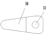
Fig. 3 is the structural representation of present embodiment tongue pressing plate;
Fig. 4 is the combination schematic representation of the utility model valve block;
Fig. 5 is the combination of side view of the utility model valve block.
Embodiment
Below in conjunction with accompanying drawing 2-5 and embodiment the technical program is further specified:
In the present embodiment, the novel valve block of a kind of air compressor, it comprises reed valve plate 20, and wherein, reed valve plate 20 1 ends are fixed end, and an end is free end, is provided with fixed hole 22 at fixed end, and reed valve plate is provided with one narrow 21.Fixed end by screw and the fixedly cooperation of aperture 22, is used for reed valve plate 20 is fixed on the air compressor body, and free end can freely lift.
The utility model is on the basis of traditional vertical bar shaped tongue compressing tablet, at reed valve plate 20 a narrow portion is set, when valve block is opened, because narrow 21 narrow compared to other positions, poor rigidity, valve block can be opened than common valve block is easier, has improved intake efficiency.
Preferably, this narrow portion is arranged on the position near reed valve plate 20 fixed ends, namely has a narrow portion in the position near fixed end, is convenient to that free end is easier to be lifted.
Be provided with a tongue pressing plate 30 at reed valve plate, the setting of tongue pressing plate 30 cooperates reed valve plate 20, can so that reed valve plate after finishing air inlet, reply closure more rapidly, thereby effectively improved valve block and opened the sensitivity of closing, thereby can improve the efficient of valve group.Concrete, tongue pressing plate 30 parts are pressed on narrow 21 of reed valve plate 20.
Claims (5)
1. novel valve block of air compressor, it comprises reed valve plate, described reed valve plate one end is fixed end, one end is free end, is provided with fixed hole at fixed end, it is characterized in that, described reed valve plate is provided with a narrow portion, and described narrow portion is arranged on the position near the reed valve plate fixed end.
2. the novel valve block of air compressor as claimed in claim 1 is characterized in that, is provided with a tongue pressing plate at described reed valve plate.
3. the novel valve block of air compressor as claimed in claim 2 is characterized in that, described tongue clamp portion is pressed on narrow of reed valve plate.
4. the novel valve block of air compressor as claimed in claim 2 is characterized in that, is provided with aperture at described tongue pressing plate end.
5. the novel valve block of air compressor as claimed in claim 4 is characterized in that, described aperture and described fixed hole overlap.
Priority Applications (1)
| Application Number | Priority Date | Filing Date | Title |
|---|---|---|---|
| CN 201320183037 CN203051051U (en) | 2013-04-12 | 2013-04-12 | Novel valve sheet of air compressor |
Applications Claiming Priority (1)
| Application Number | Priority Date | Filing Date | Title |
|---|---|---|---|
| CN 201320183037 CN203051051U (en) | 2013-04-12 | 2013-04-12 | Novel valve sheet of air compressor |
Publications (1)
| Publication Number | Publication Date |
|---|---|
| CN203051051U true CN203051051U (en) | 2013-07-10 |
Family
ID=48734010
Family Applications (1)
| Application Number | Title | Priority Date | Filing Date |
|---|---|---|---|
| CN 201320183037 Ceased CN203051051U (en) | 2013-04-12 | 2013-04-12 | Novel valve sheet of air compressor |
Country Status (1)
| Country | Link |
|---|---|
| CN (1) | CN203051051U (en) |
Cited By (2)
| Publication number | Priority date | Publication date | Assignee | Title |
|---|---|---|---|---|
| CN112797203A (en) * | 2020-12-30 | 2021-05-14 | 南京尚爱机械制造有限公司 | Check valve core assembly, manufacturing method and straight-flow check valve |
| CN115468338A (en) * | 2022-09-02 | 2022-12-13 | 宁波奥克斯电气股份有限公司 | Throttling device, throttling method and air conditioner |
-
2013
- 2013-04-12 CN CN 201320183037 patent/CN203051051U/en not_active Ceased
Cited By (3)
| Publication number | Priority date | Publication date | Assignee | Title |
|---|---|---|---|---|
| CN112797203A (en) * | 2020-12-30 | 2021-05-14 | 南京尚爱机械制造有限公司 | Check valve core assembly, manufacturing method and straight-flow check valve |
| CN115468338A (en) * | 2022-09-02 | 2022-12-13 | 宁波奥克斯电气股份有限公司 | Throttling device, throttling method and air conditioner |
| CN115468338B (en) * | 2022-09-02 | 2023-11-07 | 宁波奥克斯电气股份有限公司 | Throttling device, throttling method and air conditioner |
Similar Documents
| Publication | Publication Date | Title |
|---|---|---|
| CN203546679U (en) | Inter-segment horizontal pressure filling device for plane gate | |
| CN203536789U (en) | Door angle positioning mechanism of power distribution cabinet | |
| CN204954326U (en) | Screw mechanism is beaten in leak protection | |
| CN203712766U (en) | Compression device for die cutting machine | |
| CN204148307U (en) | A kind of buffer type hydraulic plate bending machine | |
| CN203529894U (en) | Opening device of oil containing drum | |
| CN202770140U (en) | Automatic drying device | |
| CN203072614U (en) | Ear tag pliers for animal epidemic prevention | |
| CN202926559U (en) | Valve plate of air compressor | |
| CN203066784U (en) | Door angle structure of control cabinet | |
| CN204591051U (en) | Double-layer air-permeable window | |
| CN203111934U (en) | Blanking device of needle guide machine | |
| CN204418688U (en) | A kind of little side's amount concrete casting device | |
| CN203247694U (en) | Steel structure with toe wall joint mechanism | |
| CN203683017U (en) | Multifunctional crowbar | |
| CN202045609U (en) | Dismounting tool for bound edge on automobile open-close member | |
| CN203460101U (en) | Assembled sleeve valve key | |
| CN204546062U (en) | Gearbox valve plate hold down gag | |
| CN202034178U (en) | Device for sealing crack between edge and wall of transformer oil tank | |
| CN202418147U (en) | Combined plastic buckle | |
| CN203479035U (en) | High temperature camera for industrial furnace | |
| CN204448735U (en) | Batch can gas pulsation device | |
| CN202349023U (en) | Air cylinder driven type clutch actuator | |
| CN201405274Y (en) | Flat pliers | |
| CN201442917U (en) | A New Type of Dry Quenching Furnace Roof Water Seal Tank |
Legal Events
| Date | Code | Title | Description |
|---|---|---|---|
| C14 | Grant of patent or utility model | ||
| GR01 | Patent grant | ||
| CX01 | Expiry of patent term |
Granted publication date: 20130710 |
|
| CX01 | Expiry of patent term | ||
| IW01 | Full invalidation of patent right |
Decision date of declaring invalidation: 20230105 Decision number of declaring invalidation: 59670 Granted publication date: 20130710 |
|
| IW01 | Full invalidation of patent right |