CN203050431U - Anti-prying device of vertical hinged security door - Google Patents
Anti-prying device of vertical hinged security door Download PDFInfo
- Publication number
- CN203050431U CN203050431U CN 201320041955 CN201320041955U CN203050431U CN 203050431 U CN203050431 U CN 203050431U CN 201320041955 CN201320041955 CN 201320041955 CN 201320041955 U CN201320041955 U CN 201320041955U CN 203050431 U CN203050431 U CN 203050431U
- Authority
- CN
- China
- Prior art keywords
- door
- shop front
- push
- doorframe
- security door
- Prior art date
- Legal status (The legal status is an assumption and is not a legal conclusion. Google has not performed a legal analysis and makes no representation as to the accuracy of the status listed.)
- Expired - Fee Related
Links
- 239000000463 material Substances 0.000 claims description 6
- 239000002184 metal Substances 0.000 claims description 5
- 210000002421 cell wall Anatomy 0.000 claims description 3
- 238000010586 diagram Methods 0.000 description 3
- 230000015572 biosynthetic process Effects 0.000 description 2
- 230000009286 beneficial effect Effects 0.000 description 1
- 238000010276 construction Methods 0.000 description 1
- 238000006073 displacement reaction Methods 0.000 description 1
- 230000000694 effects Effects 0.000 description 1
- 238000005516 engineering process Methods 0.000 description 1
- 238000000034 method Methods 0.000 description 1
Images


Landscapes
- Wing Frames And Configurations (AREA)
Abstract
An anti-prying device of a vertical hinged security door comprises a door frame (1) embedded into two edges of a wall body and a door face (2). The door frame (1) is a U-shaped groove, and symmetrical door face rotating positioning pin holes (5) and door face locking tongue holes (6) are formed in the groove wall. The door face (2) comprises a door leaf (3) and a pushing sliding mechanism (4), and the door leaf (3) is connected with the pushing sliding mechanism (4) through a folding hinge (7). The pushing sliding mechanism (4) comprises stretching pins (8) aligned with the door face rotating positioning pin holes (5) and extending rods (11) controlling the stretching pins (8). The anti-prying device of the vertical hinged security door has the advantages of being simple in structure, firm and capable of preventing prying.
Description
Technical field
The utility model relates to the security door technical field, relates in particular to the pick-proof technical construction of security door.
Background technology
According to country's " anti-theft safety door general technical specifications " regulation, qualified security door utilized portable power tools such as ordinary hand tools such as chisel, screwdriver, crowbar and Electric portable drill to pry open in 15 minutes or opens one 615 square millimeters opening at door leaf, or opened one 38 square millimeters opening in the semicircle of 150 square millimeters of keyed ends.Reach this requirement, particularly will reach and prevent from destroying dead bolt by crowbar, and even unload the purpose of whole door-plate, security door not only has higher requirement of strength on the material, and the structure of lockset has also been proposed more special requirement.Except main lock, also require the secondary lock of combination of interlock usually.
The design feature of serious analysis flat opening security door is not difficult to find that the security door locking is main by the dead bolt of lockset on the door-plate and tight chimeric realization of the lockhole on the doorframe.Instruments such as crowbar firmly destroy the chimeric of dead bolt and lockhole or destroy dead bolt as long as embed crack between a door and its frame, have also just realized the purpose of forcing open the door and entering the room.
Summary of the invention
The utility model provides a kind of pick-proof structure of flat opening security door just in order to address the aforementioned drawbacks, and the utlity model has simple in structure, pick-proof, firm advantage.
The purpose of this utility model is achieved by the following technical solution:
A kind of anti-picking device of flat opening security door comprises the doorframe, the shop front that embed the body of wall both sides, and the utility model doorframe is U-shaped groove, offers shop front rotational positioning pin-and-hole and the shop front locking dead bolt hole of symmetry at cell wall;
The shop front comprises door leaf and push-and-pull slide mechanism, connects by folding hinge between door leaf and the push-and-pull slide mechanism; The push-and-pull slide mechanism comprises flexible pin and the flexible stretching bar of selling of control of aiming at shop front rotational positioning hole.
The shop front is provided with door handle, and door handle inserts by lockset control dead bolt or the shop front locking dead bolt hole that contracts.
Push-and-pull slide mechanism described in the utility model comprises slide bar, is enclosed within the flexible pin at slide bar two ends, and the stretching bar is connected with flexible pin by flexure strip respectively, and the stretching bar also is connected with slide bar by spring; The front end of stretching bar is protruding.
The utility model is set with stopping means at slide bar.Stopping means is spacing ring, limited block, banking pin.
The material of the utility model doorframe is metal.
The utility model door leaf is provided with jacking block, and jacking block cooperates with the stretching bar.
The beneficial effects of the utility model are that the shop front that is made of door leaf and push-and-pull slipper slips into the on-deformable high duty metal doorframe that embeds body of wall, the dead bolt on the shop front and the tight chimeric locking that realizes of locking dead bolt hole that is hidden in the doorframe.This door is when being in the lock state, because the high duty metal doorframe is not yielding, so instruments such as crowbar put forth effort to allow the shop front of locking realize slide displacement nowhere, this has also just reached the effect that prevents from forcing open the door and enter the room.
Below in conjunction with the drawings and specific embodiments the utility model is done further explanation.
Description of drawings
Fig. 1 is the utility model locking view of closing the door.
Fig. 2 is the utility model door opening state schematic diagram.
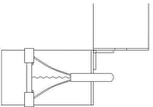
Push-and-pull slide mechanism structural behavior schematic diagram when Fig. 3 closes the door locking states for the utility model;
Push-and-pull slide mechanism structural behavior schematic diagram when Fig. 4 is the utility model door opening state.
Number in the figure is: 1, doorframe; 2, the shop front; 3, door leaf; 4, push-and-pull slide mechanism; 5, shop front rotational positioning hole; 6, shop front locking dead bolt hole; 7, folding hinge; 8, flexible pin; 9, lockset; 10, dead bolt; 11, stretching bar; 12, slide bar; 13, flexure strip; 14, spring; 15, stopping means; 16, door handle; 17, jacking block.
The specific embodiment
See Fig. 1~shown in Figure 4, a kind of anti-picking device of flat opening security door comprises the doorframe 1, the shop front 2 that embed the body of wall both sides, and the utility model doorframe 1 be U-shaped groove, and the shop front rotational positioning pin-and-hole 5 and the shop front that offer symmetry at cell wall lock dead bolt hole 6;
The shop front 2 comprises door leaf 3 and push-and-pull slide mechanism 4, connects by folding hinge 7 between door leaf 3 and the push-and-pull slide mechanism 4; Push-and-pull slide mechanism 4 comprises flexible pin 8 and flexible 8 the stretching bar 11 of selling of control of aiming at shop front rotational positioning hole 5.
The shop front 2 is provided with door handle 16, and door handle 16 inserts or the shop front locking dead bolt hole 6 that contracts by lockset 9 control dead bolts 10.
Push-and-pull slide mechanism 4 described in the utility model comprises slide bar 12, is enclosed within the flexible pin 8 at slide bar 12 two ends, and stretching bar 11 is connected with flexible pin 8 by flexure strip 13 respectively, and stretching bar 11 also is connected with slide bar 12 by spring 14; The front end of stretching bar 11 is protruding.Shop front rotational positioning pin-and-hole 5 and flexible pin 8 at intervals, and the length of flexible pin 8 wants long enough, make flexible pin 8 all not to be reduced to draw slide mechanism 4 is inner and stretch out after can snap in the shop front rotational positioning pin-and-hole 5.
The utility model is set with stopping means 15 at slide bar 12.Stopping means 15 is spacing ring, limited block, banking pin.
The material of the utility model doorframe 1 is metal.
The utility model door leaf 3 is provided with jacking block 17, and jacking block 17 cooperates with stretching bar 11.
The described shop front 2 slips into when locking a door state, rotates lockset 9, touches dead bolt 10 ejections and enters in the locking dead bolt hole 6 of doorframe 1 the pick-proof door locked; Backward rotation lockset 9 touches the locking dead bolt hole 6 that dead bolt 10 withdraws from doorframe 1, and anti-forcing open the door unblanked.
Concrete make processing can be in accordance with the following methods:
The shop front and doorframe are made: select relevant satisfactory material according to the issuing standard GB25-92 of the Ministry of Public Security " anti-theft safety door general technical specifications ", design and produce the shop front and doorframe; Select high-intensity folding hinge to connect door leaf and the push-and-pull slipper of the shop front; The shop bolt of lockset, shop front push-and-pull slipper is installed.
Install: the doorframe of security door can directly embed when body of wall is built, with the body of wall formation overall structure of combining closely; When the push-and-pull slipper of the shop front is installed, pull shop bolt by the dark hole in the door and be in retracted state, thereby easily the shop front is packed into doorframe; Pull shop bolt by the dark hole counter-rotating in the door, thereby make shop bolt be in normal operating conditions.
The utility model can at first be made the shop front and doorframe: select relevant satisfactory material according to the issuing standard GB25-92 of the Ministry of Public Security " anti-theft safety door general technical specifications ", design and produce the shop front and doorframe; Select high-intensity folding hinge to connect door leaf and the push-and-pull slipper of the shop front; The shop bolt of lockset, shop front push-and-pull slipper is installed.Install then: the doorframe of security door can directly embed when body of wall is built, with the body of wall formation overall structure of combining closely; When the push-and-pull slipper of the shop front is installed, pull shop bolt by the dark hole in the door and be in retracted state, thereby easily the shop front is packed into doorframe; Pull shop bolt by the dark hole counter-rotating in the door, thereby make shop bolt be in normal operating conditions.
Claims (5)
1. the anti-picking device of a flat opening security door, comprise the doorframe (1), the shop front (2) that embed the body of wall both sides, it is characterized in that doorframe (1) is U-shaped groove, offer shop front rotational positioning pin-and-hole (5) and the shop front locking dead bolt hole (6) of symmetry at cell wall; The shop front (2) comprises door leaf (3) and push-and-pull slide mechanism (4), connects by folding hinge (7) between door leaf (3) and the push-and-pull slide mechanism (4); Push-and-pull slide mechanism (4) comprises flexible pin (8) and the flexible stretching bar (11) of selling (8) of control of aiming at shop front rotational positioning hole (5).
2. the anti-picking device of a kind of flat opening security door according to claim 1, it is characterized in that, described push-and-pull slide mechanism (4) comprises slide bar (12), is enclosed within the flexible pin (8) at slide bar (12) two ends, stretching bar (11) is connected with flexible pin (8) by flexure strip (13) respectively, and stretching bar (11) also is connected with slide bar (12) by spring (14); The front end of stretching bar (11) is protruding.
3. the anti-picking device of a kind of flat opening security door according to claim 1 is characterized in that, the material of doorframe (1) is metal.
4. the anti-picking device of a kind of flat opening security door according to claim 2 is characterized in that, is set with stopping means (15) at slide bar (12).
5. the anti-picking device of a kind of flat opening security door according to claim 1 is characterized in that, door leaf (3) is provided with jacking block (17), and jacking block (17) cooperates with stretching bar (11).
Priority Applications (1)
| Application Number | Priority Date | Filing Date | Title |
|---|---|---|---|
| CN 201320041955 CN203050431U (en) | 2013-01-25 | 2013-01-25 | Anti-prying device of vertical hinged security door |
Applications Claiming Priority (1)
| Application Number | Priority Date | Filing Date | Title |
|---|---|---|---|
| CN 201320041955 CN203050431U (en) | 2013-01-25 | 2013-01-25 | Anti-prying device of vertical hinged security door |
Publications (1)
| Publication Number | Publication Date |
|---|---|
| CN203050431U true CN203050431U (en) | 2013-07-10 |
Family
ID=48733396
Family Applications (1)
| Application Number | Title | Priority Date | Filing Date |
|---|---|---|---|
| CN 201320041955 Expired - Fee Related CN203050431U (en) | 2013-01-25 | 2013-01-25 | Anti-prying device of vertical hinged security door |
Country Status (1)
| Country | Link |
|---|---|
| CN (1) | CN203050431U (en) |
Cited By (1)
| Publication number | Priority date | Publication date | Assignee | Title |
|---|---|---|---|---|
| CN113389472A (en) * | 2020-03-13 | 2021-09-14 | 中国铁塔股份有限公司驻马店市分公司 | Anti-prying device for embedded security door |
-
2013
- 2013-01-25 CN CN 201320041955 patent/CN203050431U/en not_active Expired - Fee Related
Cited By (1)
| Publication number | Priority date | Publication date | Assignee | Title |
|---|---|---|---|---|
| CN113389472A (en) * | 2020-03-13 | 2021-09-14 | 中国铁塔股份有限公司驻马店市分公司 | Anti-prying device for embedded security door |
Similar Documents
| Publication | Publication Date | Title |
|---|---|---|
| CN204462222U (en) | A kind of anti-electricity-theft device of ammeter box | |
| CN203640569U (en) | Double-leaf antitheft fire-fighting door | |
| CN201110068Y (en) | a door lock | |
| CN201661146U (en) | Lock capable of locking double wing door with postern | |
| CN202596551U (en) | Prying resistant mechanism of rolling shutter door | |
| CN202023415U (en) | Novel door lock | |
| CN201902077U (en) | Fence lock | |
| CN203223107U (en) | Safe box | |
| CN202299726U (en) | Concealed mounted-type composite safety door lock | |
| CN203201300U (en) | Prying-resistant structure of mortise lock | |
| CN202788304U (en) | Entrance guard unlocking device | |
| CN109555436A (en) | A kind of polygon locking security door | |
| CN201318105Y (en) | A burglar-proof door with an automatic alarm handle | |
| CN202325115U (en) | Fire-protection and anti-theft door | |
| CN201292747Y (en) | Automatic alarm anti-theft door | |
| EP2171184A1 (en) | Lock for reinforced doors and the like | |
| CN204311865U (en) | Electronic linkage door lock mechanism | |
| CN203905754U (en) | Curved structure anti-theft door | |
| CN202347944U (en) | Mechanical lock | |
| CN203742422U (en) | Lock special for electric roller shutter | |
| CN204386310U (en) | Sash safe antitheft plate | |
| CN205153917U (en) | Antitheft door structure | |
| CN2926407Y (en) | Sided lock of safety door | |
| CN203547441U (en) | Anti-pry anti-dial anti-theft door | |
| CN200971640Y (en) | Fire-proof door handle with lock for locking and unlocking |
Legal Events
| Date | Code | Title | Description |
|---|---|---|---|
| C14 | Grant of patent or utility model | ||
| GR01 | Patent grant | ||
| CF01 | Termination of patent right due to non-payment of annual fee |
Granted publication date: 20130710 Termination date: 20180125 |
|
| CF01 | Termination of patent right due to non-payment of annual fee |