CN203019088U - Clamping locating device for die insert combination - Google Patents
Clamping locating device for die insert combination Download PDFInfo
- Publication number
- CN203019088U CN203019088U CN 201220646618 CN201220646618U CN203019088U CN 203019088 U CN203019088 U CN 203019088U CN 201220646618 CN201220646618 CN 201220646618 CN 201220646618 U CN201220646618 U CN 201220646618U CN 203019088 U CN203019088 U CN 203019088U
- Authority
- CN
- China
- Prior art keywords
- clamping
- insert
- locating piece
- shaped nut
- locating
- Prior art date
- Legal status (The legal status is an assumption and is not a legal conclusion. Google has not performed a legal analysis and makes no representation as to the accuracy of the status listed.)
- Expired - Fee Related
Links
- 229910000831 Steel Inorganic materials 0.000 claims description 3
- 239000010959 steel Substances 0.000 claims description 3
- 238000003754 machining Methods 0.000 abstract description 6
- 230000008901 benefit Effects 0.000 abstract description 2
- 238000000034 method Methods 0.000 description 8
- 230000008569 process Effects 0.000 description 4
- 230000004807 localization Effects 0.000 description 3
- 239000012467 final product Substances 0.000 description 2
- 230000006872 improvement Effects 0.000 description 2
- 238000004519 manufacturing process Methods 0.000 description 2
- 230000009471 action Effects 0.000 description 1
- 238000010923 batch production Methods 0.000 description 1
- 239000002131 composite material Substances 0.000 description 1
- 238000010586 diagram Methods 0.000 description 1
- 238000005516 engineering process Methods 0.000 description 1
- 238000009434 installation Methods 0.000 description 1
- 230000007246 mechanism Effects 0.000 description 1
- 230000008520 organization Effects 0.000 description 1
Images


Landscapes
- Jigs For Machine Tools (AREA)
Abstract
The utility model discloses a clamping locating device for die insert combination. The clamping locating device is characterized in that criss-cross T grooves are formed in an auxiliary clamping working platform, a T-shaped nut is arranged at the position where the T grooves intersect, a cross locating block is arranged on the T-shaped nut, another T-shaped nut is installed inside a T groove of the auxiliary clamping working platform, a locating block is arranged on the T-shaped nut, a locating screw penetrates through an insert to be fixed to the cross locating block to be used as a machining center and another locating screw penetrates through the insert to be fixed in the locating block to be used as another fixing point. Due to the fact that the structure is adopted, the clamping locating device for die inset combination has the advantages that the insert is guaranteed to be located quickly on a numerical control machine tool, clamping efficiency is improved, the insert is clamped and locked through a combination device of the locating screw and the locking block, the insert cannot be affected by stress during machining to move in the machining process, and quality stability of machined inserts is improved.
Description
Technical field
The utility model relates to the manufacturing field of mould, particularly a kind of clamping and positioning device of die insert combination.
Background technology
In order to satisfy client's delivery date, inserting needs and the production of die holder parallel organization, therefore the die insert single-piece work produces thereupon at die industry.
Insert small numerical control lathe single-piece thick/semifinishing profile, profile, just process need to be on lathe positioning and clamping, the positioning and clamping method of using at present is that this positioning and clamping method is consuming time, efficient is low by centimeter check barricade, the stretching setting centralized positioning of piece.Because a mold generally contains a plurality of inserting, the installation way of this poor efficiency causes the auxiliary clamping time to greatly increase.And because the pressured board clamping device inserted compresses, insert in process and easily move because of stressed, cause processing the quality of inserting unstable.
For above-mentioned problem, a kind of clamping and positioning device that meets the single-piece work of inserting is provided, making inserts can locate fast on lathe and be fixedly the problem that prior art need to solve.
The utility model content
Technical problem to be solved in the utility model is to provide a kind of clamping and positioning device of die insert combination, the purpose that making inserts can locate fast on lathe and fix.
For achieving the above object, the technical solution of the utility model is, a kind of clamping and positioning device of die insert combination, and it is characterized in that: described positioner is that the auxiliary clamping workbench is provided with crisscross T groove; The intersection of T groove is provided with a T-shaped nut, and T-shaped nut is provided with the cross locating piece, and the T-shaped nut of another piece is installed in the T groove of auxiliary clamping workbench, and the above is provided with locating piece; Dog screw passes to insert and is fixed to the cross locating piece as machining center, and another dog screw passes to insert and is fixed on locating piece as another fixing point, thereby realizes fixing to what insert.
Be respectively equipped with pin-and-hole on two diagonal angles of described auxiliary clamping workbench, make the auxiliary clamping workbench navigate on Digit Control Machine Tool fast.
The T groove of described auxiliary clamping workbench is parallel with X, the Y-axis of Digit Control Machine Tool respectively.
Described cross locating piece, locating piece, dog screw, T-shaped nut, auxiliary clamping workbench are the 45# steel, are quenched to HRC30-35.
A kind of clamping and positioning device of die insert combination owing to adopting above-mentioned structure, the utility model has the advantage of: 1, guarantee to insert and locate fast on Digit Control Machine Tool, improve clamping efficient; 2, insert by dog screw and the locking of locating piece composite set clamping, can because processing stressed the movement, not improve the stability of processing the quality of inserting in process.
Description of drawings
Below in conjunction with the drawings and specific embodiments, the utility model is described in further detail;
Fig. 1 is the structural representation of the clamping and positioning device of a kind of die insert combination of the utility model;
Fig. 2 is the cross-sectional view of the clamping and positioning device of a kind of die insert combination of the utility model;
Fig. 3 is the top surface structure schematic diagram of the clamping and positioning device of a kind of die insert combination of the utility model;
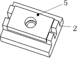
Fig. 4 is the T-shaped nut of clamping and positioning device of a kind of die insert combination of the utility model and the structural representation of locating piece;
In Fig. 1-4,1, the auxiliary clamping workbench; 2, T-shaped nut; 3, cross locating piece; 4, dog screw; 5, locating piece; 6, insert; 7, pin-and-hole.
The specific embodiment
As shown in Figure 1, the utility model is that auxiliary clamping workbench 1 is provided with crisscross T groove; The intersection of T groove is provided with a T-shaped nut 2, and T-shaped nut 2 is provided with cross locating piece 3, and the T-shaped nut 2 of another piece is installed in the T groove of auxiliary clamping workbench 1, and the above is provided with locating piece 5; Dog screw 4 passes to insert and 6 is fixed to cross locating piece 3 as machining center, and dog screw 4 passes to insert and 6 is fixed on locating piece 5 as another fixing point, thus realize to insert 6 fixing.Be respectively equipped with pin-and-hole 7 on two diagonal angles of auxiliary clamping workbench 1, make auxiliary clamping workbench 1 navigate on Digit Control Machine Tool fast.
Operation principle of the present utility model is the plane and two pits location, but have greatly again different from the past plane and two pits location, the two relative workbench of pin of plane and two pits were fixed in the past, so just require two on processing work relatively fixing for the fixing hole of location, can only be used for batch production, and in this detent mechanism, the fixing hole on locating piece 5 can move relative to the T of auxiliary clamping workbench 1 groove in a direction, so just can guarantee in Fig. 2 that size △ L is inserted by processing 6 determines, can move in a direction due to locating piece 5 simultaneously and avoid crossing the location.Thereby make this positioner be applied to the die industry single-piece work and insert 6.
Clamping and positioning device mainly is comprised of the two large divisions: 1. setting element: locating piece 5, cross locating piece 3, dog screw 4, auxiliary clamping workbench 1,2. clamping device: T-shaped nut 2, dog screw 4.Wherein the existing positioning action of dog screw 4, also have the locking effect.
6 location on lathe of inserting are mainly completed by two steps.1. fixture should occupy relatively accurate position on lathe, this is to be guaranteed by the connecting surface of fixture and lathe and corresponding Connection Element, and namely cross locating piece 3 coordinates 28H7/h7 to reach the six-freedom degree that contacts to limit cross locating piece 3 with T-shaped nut 2 upper surfaces with the T groove localization part of auxiliary clamping workbench 1.Guarantee that on cross locating piece 3, fixing hole Φ D occupies a correct position on lathe, the center in its Φ D hole is 6 the machining center of inserting.Locating piece 5 coordinates 28H7/h7 to reach 5 frees degree that contact to limit locating piece 5 with T-shaped nut 2 upper surfaces with the T groove localization part of auxiliary clamping workbench 1.Locating piece 5 can be moved relative to auxiliary clamping workbench 1 in a direction, determined by size on workpiece to guarantee size △ L, simultaneously because the removable workpiece of having avoided of locating piece 5 one directions is crossed the location.2. 6 location on fixture of inserting are cooperations of positioning reference plane and the location working face of fixture setting element by workpiece or contact to realize, namely insert 6 bottom surface contacts with work top, restriction insert 6 Z direction one-movement-freedom-degree and X, Y rotary freedom, one the location screw 4 with insert 6 and cross locating piece 3 coordinate, X, the Y-direction one-movement-freedom-degree of restriction workpiece, the pin of another dog screw 4 part with insert 6 and locating piece 5 coordinate to limit 6 the Z direction rotation free degree of inserting.Thereby determine the position that workpiece occupies on lathe.
Concrete fixation procedure is: auxiliary clamping workbench 1 and platen location.Pass through for the first time centimeter check, guarantee that horizontal, vertical T groove is respectively at platen X, Y-direction is parallel, with itself and table latch, the fixing hole of processing two Φ 20H7, directly can with the pin positioning instant when again auxiliary table 1 being installed later on to platen and allocate Φ 20h6 pin on auxiliary clamping workbench 1.Two T-shaped nuts 2 are put into the T groove of auxiliary table, one of them T-shaped nut 4 is placed on right-angled intersection place again.Cross locating piece 3 is placed on T-shaped nut 4, and it is coordinated in T groove localization part.When using for the first time, detecting on cross locating piece 3 the fixing hole position, it is made as machining coordinate is initial point, and deposits lathe in, adds later on man-hour, and cross locating piece 3 is placed on and where just calls as machining coordinate is that initial point gets final product.Insert and 6 select pitch-row 2 screw via holes farthest to be processed into corresponding fixing hole when the preorder machining prgraming.Provide one of them screw coordinate and center, the line in two holes is X-axis, and vertical bottom face is Z axis, and vertical XZ face is that Y-axis is set coordinate system.Will process inserts 6 is put on auxiliary clamping workbench 1, the installing hole of inserting on 6 is overlapped, by the distance of inserting 6 installing holes with cross locating piece 3 installing holes, in order to determine the placement location of locating piece, locking positioning screw 4, calling machining coordinate is that application program processing gets final product.
Cross locating piece 3, locating piece 5, dog screw 4, T-shaped nut 2, auxiliary clamping workbench 1 are the 45# steel, are quenched to HRC30-35.
The utility model can make fast to insert and 6 occupy a correct Working position on lathe, and need not traditional stretching centering can direct working procedure processing.Shorten the clamping time, guarantee simultaneously insert 6 quality of processing.
The above is exemplarily described the utility model by reference to the accompanying drawings; obviously the utility model specific implementation is not subject to the restrictions described above; as long as the various improvement of having adopted technical solutions of the utility model to carry out; or directly apply to other occasion without improvement, all within protection domain of the present utility model.
Claims (4)
1. the clamping and positioning device of die insert combination, it is characterized in that: described positioner is that auxiliary clamping workbench (1) is provided with crisscross T groove; The intersection of T groove is provided with a T-shaped nut (2), and T-shaped nut (2) is provided with cross locating piece (3), and the T-shaped nut of another piece (2) is installed in the T groove of auxiliary clamping workbench (1), and the above is provided with locating piece (5); Dog screw (4) passes insert (6) and is fixed to cross locating piece (3) as machining center, and another dog screw (4) passes insert (6) and is fixed to locating piece (5) upward as another fixing point.
2. the clamping and positioning device of a kind of die insert combination according to claim 1, is characterized in that: be respectively equipped with pin-and-hole (7) on two diagonal angles of described auxiliary clamping workbench (1).
3. the clamping and positioning device of a kind of die insert combination according to claim 1, it is characterized in that: the T groove of described auxiliary clamping workbench (1) is parallel with X, the Y-axis of Digit Control Machine Tool respectively.
4. the clamping and positioning device of according to claim 1 and 2 or 3 described a kind of die inserts combinations, it is characterized in that: described cross locating piece (3), locating piece (5), dog screw (4), T-shaped nut (2), auxiliary clamping workbench (1) are the 45# steel, are quenched to HRC30-35.
Priority Applications (1)
| Application Number | Priority Date | Filing Date | Title |
|---|---|---|---|
| CN 201220646618 CN203019088U (en) | 2012-11-30 | 2012-11-30 | Clamping locating device for die insert combination |
Applications Claiming Priority (1)
| Application Number | Priority Date | Filing Date | Title |
|---|---|---|---|
| CN 201220646618 CN203019088U (en) | 2012-11-30 | 2012-11-30 | Clamping locating device for die insert combination |
Publications (1)
| Publication Number | Publication Date |
|---|---|
| CN203019088U true CN203019088U (en) | 2013-06-26 |
Family
ID=48643102
Family Applications (1)
| Application Number | Title | Priority Date | Filing Date |
|---|---|---|---|
| CN 201220646618 Expired - Fee Related CN203019088U (en) | 2012-11-30 | 2012-11-30 | Clamping locating device for die insert combination |
Country Status (1)
| Country | Link |
|---|---|
| CN (1) | CN203019088U (en) |
Cited By (9)
| Publication number | Priority date | Publication date | Assignee | Title |
|---|---|---|---|---|
| CN103465057A (en) * | 2013-08-30 | 2013-12-25 | 安徽池州家用机床股份有限公司 | Fixture for turning of hitching legs |
| CN103962846A (en) * | 2014-04-07 | 2014-08-06 | 韩学伟 | Vertical and horizontal cutting universal workbench |
| CN105500052A (en) * | 2014-09-25 | 2016-04-20 | 安徽池州项赛机械制造有限公司 | Supporting seat slot clamp |
| CN106239196A (en) * | 2016-08-26 | 2016-12-21 | 中航动力股份有限公司 | A kind of annular flame tube floating wall tile stud processing milling machine fixture and localization method |
| CN107901336A (en) * | 2017-12-13 | 2018-04-13 | 珀尔曼机电(昆山)有限公司 | A kind of portable Quick mould auxiliary body |
| CN109648751A (en) * | 2018-12-25 | 2019-04-19 | 中国航空工业集团公司基础技术研究院 | A kind of integrated apparatus that is located by connecting suitable for composable mold |
| CN109926853A (en) * | 2019-04-28 | 2019-06-25 | 华域视觉科技(上海)有限公司 | A kind of horizontal machine tool clamping tool |
| CN110919410A (en) * | 2019-12-05 | 2020-03-27 | 豪尔沃(山东)机械科技有限公司 | A Precise and Fast Repeated Clamping Device |
| CN112916748A (en) * | 2020-12-29 | 2021-06-08 | 中国第一汽车股份有限公司 | Automatic machining line lower straightening device and method for small insert of automobile cold stamping die |
-
2012
- 2012-11-30 CN CN 201220646618 patent/CN203019088U/en not_active Expired - Fee Related
Cited By (11)
| Publication number | Priority date | Publication date | Assignee | Title |
|---|---|---|---|---|
| CN103465057A (en) * | 2013-08-30 | 2013-12-25 | 安徽池州家用机床股份有限公司 | Fixture for turning of hitching legs |
| CN103962846A (en) * | 2014-04-07 | 2014-08-06 | 韩学伟 | Vertical and horizontal cutting universal workbench |
| CN105500052A (en) * | 2014-09-25 | 2016-04-20 | 安徽池州项赛机械制造有限公司 | Supporting seat slot clamp |
| CN106239196A (en) * | 2016-08-26 | 2016-12-21 | 中航动力股份有限公司 | A kind of annular flame tube floating wall tile stud processing milling machine fixture and localization method |
| CN106239196B (en) * | 2016-08-26 | 2018-05-29 | 中航动力股份有限公司 | A kind of annular flame tube floating wall tile stud processing milling machine fixture and localization method |
| CN107901336A (en) * | 2017-12-13 | 2018-04-13 | 珀尔曼机电(昆山)有限公司 | A kind of portable Quick mould auxiliary body |
| CN109648751A (en) * | 2018-12-25 | 2019-04-19 | 中国航空工业集团公司基础技术研究院 | A kind of integrated apparatus that is located by connecting suitable for composable mold |
| CN109926853A (en) * | 2019-04-28 | 2019-06-25 | 华域视觉科技(上海)有限公司 | A kind of horizontal machine tool clamping tool |
| CN109926853B (en) * | 2019-04-28 | 2023-12-05 | 华域视觉科技(武汉)有限公司 | Clamping tool for horizontal machine tool |
| CN110919410A (en) * | 2019-12-05 | 2020-03-27 | 豪尔沃(山东)机械科技有限公司 | A Precise and Fast Repeated Clamping Device |
| CN112916748A (en) * | 2020-12-29 | 2021-06-08 | 中国第一汽车股份有限公司 | Automatic machining line lower straightening device and method for small insert of automobile cold stamping die |
Similar Documents
| Publication | Publication Date | Title |
|---|---|---|
| CN103231247B (en) | A kind of turntable type multi-head numerical control drilling and tapping machine tool | |
| CN101905341B (en) | Method for processing double-sided inclined plane of part on one station | |
| CN103949909B (en) | A kind of CNC processes spherical parts built-up jig and clamping method | |
| CN204053583U (en) | A kind of axis products clamping device | |
| CN101870004A (en) | Fixture for batch processing of inflating model fixing seat | |
| CN104175150A (en) | Pressure casting transformed special-shaped product hole positioning pneumatic clamp and clamping method | |
| CN203141150U (en) | Machining locating tool used for horizontal machining center | |
| CN204209477U (en) | A kind of die casting modified product hole locating pneumatic fixture | |
| CN110757213A (en) | Multi-station vertical machining center four-axis hydraulic clamp | |
| CN203875668U (en) | Locating device for machining | |
| CN204135752U (en) | Quick resetting clamping device | |
| CN200991820Y (en) | Quick-positioning machine tool operation table | |
| CN203210078U (en) | Workpiece processing device of numerical control equipment | |
| CN103659317B (en) | Jacking clamp and machine tool with same | |
| CN202779903U (en) | Processing device for brake hub | |
| CN106271888A (en) | A kind of vertical machining device of Electromechanical Control | |
| CN204053594U (en) | A kind of not rounded base type round boss product clamping device | |
| CN204621610U (en) | Tool rest fine finishining frock clamp | |
| CN200991821Y (en) | Quick-positioning machine tool operation table | |
| CN103170867A (en) | Device of computerized numerical control (CNC) equipment machining workpiece and working method thereof | |
| CN102357815B (en) | Numerical control processing method and special processing fixture for inertial platform body | |
| CN203125156U (en) | Cylindrical part rapid clamping and locating fixture | |
| CN221210691U (en) | A double-station processing tool | |
| CN203649407U (en) | Long plug pin lathe | |
| CN101456110B (en) | Precise positioner for secondary cutting workpiece of numerical control cutting machine and positioning method |
Legal Events
| Date | Code | Title | Description |
|---|---|---|---|
| C14 | Grant of patent or utility model | ||
| GR01 | Patent grant | ||
| CF01 | Termination of patent right due to non-payment of annual fee |
Granted publication date: 20130626 Termination date: 20151130 |
|
| EXPY | Termination of patent right or utility model |