CN202967529U - Grabbing mechanism of sorting machine - Google Patents
Grabbing mechanism of sorting machine Download PDFInfo
- Publication number
- CN202967529U CN202967529U CN 201220664373 CN201220664373U CN202967529U CN 202967529 U CN202967529 U CN 202967529U CN 201220664373 CN201220664373 CN 201220664373 CN 201220664373 U CN201220664373 U CN 201220664373U CN 202967529 U CN202967529 U CN 202967529U
- Authority
- CN
- China
- Prior art keywords
- ball bearing
- box
- utility
- model
- main shaft
- Prior art date
- Legal status (The legal status is an assumption and is not a legal conclusion. Google has not performed a legal analysis and makes no representation as to the accuracy of the status listed.)
- Expired - Fee Related
Links
Images

Landscapes
- Rollers For Roller Conveyors For Transfer (AREA)
Abstract
本实用新型公开了一种分检机抓取机构,导柱滑杆固定在铝型材支架上面,所述导柱滑杆的右端与第一箱式滚珠轴承的一端连接,所述第一箱式滚珠轴承的右端安装有夹具,所述第一箱式滚珠轴承的另一端固定于梯形丝杆的右端,所述梯形丝杆的另一段通过带座轴承与同步带轮连接,所述同步带轮安装在同步带的里圈。本实用新型技术方案的应用,可以实现不同尺寸组件的抓取,可以采用自动化搬运从而提高生产效率。
The utility model discloses a grabbing mechanism of a sorting machine. The guide post slide bar is fixed on the aluminum profile support, the right end of the guide post slide bar is connected with one end of a first box-type ball bearing, and the first box-type The right end of the ball bearing is equipped with a fixture, the other end of the first box-type ball bearing is fixed on the right end of the trapezoidal screw, and the other section of the trapezoidal screw is connected to the synchronous pulley through a bearing with seat, and the synchronous pulley Installed on the inner ring of the timing belt. The application of the technical solution of the utility model can realize the grabbing of components of different sizes, and can adopt automatic handling to improve production efficiency.
Description
技术领域 technical field
本实用新型涉及一种太阳能生产线设备,具体涉及一种分检机抓取机构。 The utility model relates to a solar energy production line equipment, in particular to a grabbing mechanism of a sorting machine.
背景技术 Background technique
该机构专用于太阳能组件流水线自动分检工位,其主要功能是将组件从流水线上抓取层叠放入栈板。此种可调节夹具的方式可实现不同尺寸组件的抓取。目前,光伏组件输送线在组件组装成成品后放入栈板,这个环节普遍采用人工搬运,或是半自动化搬运。而且人工搬运会导致流水线挡线,降低生产效率。 This mechanism is dedicated to the automatic sorting station of the solar module assembly line, and its main function is to grab and stack the modules from the assembly line and put them on the pallet. This way of adjustable clamps can realize the grabbing of components of different sizes. At present, the photovoltaic module conveying line is put into pallets after the modules are assembled into finished products. This link generally adopts manual handling or semi-automatic handling. Moreover, manual handling will cause the assembly line to block the line and reduce production efficiency.
实用新型内容 Utility model content
本实用新型的目的在于克服现有技术存在的以上问题,提供一种分检机抓取机构。 The purpose of the utility model is to overcome the above problems existing in the prior art, and to provide a sorting machine grasping mechanism.
为实现上述技术目的,达到上述技术效果,本实用新型通过以下技术方案实现: In order to achieve the above-mentioned technical purpose and achieve the above-mentioned technical effect, the utility model is realized through the following technical solutions:
一种分检机抓取机构,导柱滑杆固定在铝型材支架上面,所述导柱滑杆的右端与第一箱式滚珠轴承的一端连接,所述第一箱式滚珠轴承的右端安装有夹具,所述第一箱式滚珠轴承的另一端固定于梯形丝杆的右端,所述梯形丝杆的另一段通过带座轴承与同步带轮连接,所述同步带轮安装在同步带的里圈,所述夹具下方安装有缓冲垫,所述缓冲垫右侧安装有手摇扳手,所述手摇扳手下方安装有传感器固定板,所述传感器固定板与气缸推板的一侧相连接,所述气缸推板的内侧安装有气缸,所述气缸安装于长箱体轴承连接板上,所述长箱体轴承连接板的下端安装有第二箱式滚珠轴承,所述第二箱式滚珠轴承的左侧与导杆相连接。 A grabbing mechanism for a sorting machine, the guide column slide bar is fixed on the aluminum profile bracket, the right end of the guide post slide bar is connected to one end of the first box-type ball bearing, and the right end of the first box-type ball bearing is installed There is a fixture, the other end of the first box-type ball bearing is fixed to the right end of the trapezoidal screw, and the other section of the trapezoidal screw is connected to the synchronous pulley through a bearing with seat, and the synchronous pulley is installed on the synchronous belt In the inner ring, a buffer pad is installed under the clamp, a hand wrench is installed on the right side of the buffer pad, a sensor fixing plate is installed under the hand wrench, and the sensor fixing plate is connected to one side of the cylinder push plate , the inner side of the cylinder push plate is installed with a cylinder, the cylinder is installed on the long box bearing connecting plate, the lower end of the long box bearing connecting plate is installed with a second box type ball bearing, the second box type The left side of the ball bearing is connected to the guide rod.
本实用新型的有益效果是: The beneficial effects of the utility model are:
本实用新型的应用,可以实现不同尺寸组件的抓取,可以采用自动化搬运从而提高生产效率。 The application of the utility model can realize grabbing of components of different sizes, and can adopt automatic handling to improve production efficiency.
本实用新型的原理是: The principle of the utility model is:
用手摇动手摇扳手转动梯形丝杆,梯形丝杆可以带动夹具、气缸推板和长箱体轴承连接板整体前后移动,从而调节夹具夹取不同尺寸的组件;位置调节好之后,通过电气控制气缸自动顶升夹具、气缸推板向前推进夹紧组件边框。箱式滚珠轴承二和导杆配合起到气缸顶升的导向作用。 Turn the trapezoidal screw with a manual wrench, the trapezoidal screw can drive the fixture, the cylinder push plate and the long box bearing connecting plate to move back and forth as a whole, so as to adjust the fixture to pick up components of different sizes; after the position is adjusted, through electrical control The cylinder automatically lifts the clamp, and the cylinder push plate pushes forward to clamp the frame of the assembly. The box-type ball bearing two cooperates with the guide rod to play the guiding role of cylinder jacking.
上述说明仅是本实用新型技术方案的概述,为了能够更清楚了解本实用新型的技术手段,并可依照说明书的内容予以实施,以下以本实用新型的较佳实施例并配合附图详细说明如后。本实用新型的具体实施方式由以下实施例及其附图详细给出。 The above description is only an overview of the technical solution of the utility model. In order to understand the technical means of the utility model more clearly and implement it according to the contents of the specification, the following is a detailed description of the preferred embodiment of the utility model with accompanying drawings. back. The specific embodiment of the utility model is given in detail by the following examples and accompanying drawings.
附图说明 Description of drawings
此处所说明的附图用来提供对本实用新型的进一步理解,构成本申请的一部分,本实用新型的示意性实施例及其说明用于解释本实用新型,并不构成对本实用新型的不当限定。在附图中: The drawings described here are used to provide a further understanding of the utility model and constitute a part of the application. The schematic embodiments of the utility model and their descriptions are used to explain the utility model and do not constitute improper limitations to the utility model. In the attached picture:
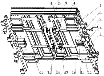
图1为本实用新型的结构示意图。 Fig. 1 is the structural representation of the utility model.
图中标号说明:1、铝型材支架,2、导柱滑杆,3、梯形丝杆,4、第一箱式滚珠轴承,5、夹具,6、缓冲垫,7、手摇扳手,8、传感器固定板,9、气缸推板,10、第二箱式滚珠轴承,11、气缸,12、导杆,13、带座轴承,14、同步带,15、同步带轮,16、长箱体轴承连接板。 Explanation of symbols in the figure: 1. Aluminum profile bracket, 2. Guide column slide rod, 3. Trapezoidal screw rod, 4. The first box-type ball bearing, 5. Fixture, 6. Cushion pad, 7. Hand wrench, 8. Sensor fixed plate, 9, cylinder push plate, 10, second box type ball bearing, 11, cylinder, 12, guide rod, 13, belt seat bearing, 14, synchronous belt, 15, synchronous pulley, 16, long box Bearing connection plate.
具体实施方式 Detailed ways
下面将参考附图并结合实施例,来进一步说明本实用新型。 The utility model will be further described below with reference to the accompanying drawings and in conjunction with the embodiments.
本实用新型提出了一种分检机抓取机构。参照图1所示,一种分检机抓取机构,导柱滑杆2固定在铝型材支架1上面,所述导柱滑杆2的右端与第一箱式滚珠轴承4的一端连接,所述第一箱式滚珠轴承4的右端安装有夹具5,所述第一箱式滚珠轴承4的另一端固定于梯形丝杆3的右端,所述梯形丝杆3的另一段通过带座轴承13与同步带轮15连接,所述同步带轮15安装在同步带14的里圈,所述夹具5下方安装有缓冲垫6,所述缓冲垫6右侧安装有手摇扳手7,所述手摇扳手7下方安装有传感器固定板8,所述传感器固定板(8)与气缸推板9的一侧相连接,所述气缸推板9的内侧安装有气缸11,所述气缸11安装于长箱体轴承连接板16上,所述长箱体轴承连接板16的下端安装有第二箱式滚珠轴承10,所述第二箱式滚珠轴承10的左侧与导杆12相连接。
The utility model provides a sorting machine grasping mechanism. Referring to Fig. 1, a sorting machine grasping mechanism, the guide column slide bar 2 is fixed on the aluminum profile bracket 1, the right end of the guide post slide bar 2 is connected with one end of the first box-type ball bearing 4, the The right end of the first box-type ball bearing 4 is equipped with a fixture 5, the other end of the first box-type ball bearing 4 is fixed on the right end of the trapezoidal screw 3, and the other section of the trapezoidal screw 3 passes through the bearing 13 Connect with
以上所述仅为本实用新型的优选实施例而已,并不用于限制本实用新型,对于本领域的技术人员来说,本实用新型可以有各种更改和变化。凡在本实用新型的精神和原则之内,所作的任何修改、等同替换、改进等,均应包含在本实用新型的保护范围之内。 The above descriptions are only preferred embodiments of the utility model, and are not intended to limit the utility model. For those skilled in the art, the utility model can have various modifications and changes. Any modification, equivalent replacement, improvement, etc. made within the spirit and principles of the present utility model shall be included in the protection scope of the present utility model.
Claims (1)
Priority Applications (1)
| Application Number | Priority Date | Filing Date | Title |
|---|---|---|---|
| CN 201220664373 CN202967529U (en) | 2012-12-06 | 2012-12-06 | Grabbing mechanism of sorting machine |
Applications Claiming Priority (1)
| Application Number | Priority Date | Filing Date | Title |
|---|---|---|---|
| CN 201220664373 CN202967529U (en) | 2012-12-06 | 2012-12-06 | Grabbing mechanism of sorting machine |
Publications (1)
| Publication Number | Publication Date |
|---|---|
| CN202967529U true CN202967529U (en) | 2013-06-05 |
Family
ID=48508635
Family Applications (1)
| Application Number | Title | Priority Date | Filing Date |
|---|---|---|---|
| CN 201220664373 Expired - Fee Related CN202967529U (en) | 2012-12-06 | 2012-12-06 | Grabbing mechanism of sorting machine |
Country Status (1)
| Country | Link |
|---|---|
| CN (1) | CN202967529U (en) |
Cited By (3)
| Publication number | Priority date | Publication date | Assignee | Title |
|---|---|---|---|---|
| CN103848209A (en) * | 2012-12-06 | 2014-06-11 | 苏州宏瑞达新能源装备有限公司 | Grabbing mechanism of sorting and picking machine |
| CN107902349A (en) * | 2017-11-28 | 2018-04-13 | 醴陵市绿源商贸有限公司 | A material distribution box frame fixture and its movement control method |
| CN117047432A (en) * | 2023-08-21 | 2023-11-14 | 河南科技大学 | A flexible installation fixture for photovoltaic panels |
-
2012
- 2012-12-06 CN CN 201220664373 patent/CN202967529U/en not_active Expired - Fee Related
Cited By (5)
| Publication number | Priority date | Publication date | Assignee | Title |
|---|---|---|---|---|
| CN103848209A (en) * | 2012-12-06 | 2014-06-11 | 苏州宏瑞达新能源装备有限公司 | Grabbing mechanism of sorting and picking machine |
| CN103848209B (en) * | 2012-12-06 | 2017-03-15 | 苏州宏瑞达新能源装备有限公司 | A kind of sorting machine grasping mechanism |
| CN107902349A (en) * | 2017-11-28 | 2018-04-13 | 醴陵市绿源商贸有限公司 | A material distribution box frame fixture and its movement control method |
| CN107902349B (en) * | 2017-11-28 | 2019-11-22 | 醴陵市绿源商贸有限公司 | A material distribution box frame fixture and its movement control method |
| CN117047432A (en) * | 2023-08-21 | 2023-11-14 | 河南科技大学 | A flexible installation fixture for photovoltaic panels |
Similar Documents
| Publication | Publication Date | Title |
|---|---|---|
| CN202499548U (en) | Automatic loading and unloading system | |
| CN204264860U (en) | A kind of graphite boat jacking system | |
| CN105129418B (en) | A kind of feeding double-purpose clamping jaw | |
| CN205928338U (en) | Clamping device | |
| CN202054443U (en) | Electric energy meter carrying manipulator applicable to meter box | |
| CN103848209B (en) | A kind of sorting machine grasping mechanism | |
| CN103848248A (en) | Lifting grabbing and turning mechanism | |
| CN202295402U (en) | Tile piling device of stacking machine | |
| CN103253402A (en) | Full automatic packing machine | |
| CN111312640B (en) | A translational dislocation floating clamping mechanism | |
| CN203095209U (en) | Lifting, gripping and turning mechanism | |
| CN206580291U (en) | A kind of glass grips shift unit | |
| CN202684531U (en) | Automatic workbench lifting device | |
| CN203714305U (en) | Steel bracket clamping device with double bevels | |
| CN203699298U (en) | Tray reshaping mechanism for tray separating machine | |
| CN203865568U (en) | Multi-station glass sheet taking machine | |
| CN202423354U (en) | Clamping type overturning device of crystalline silicon photovoltaic component | |
| CN102910409B (en) | Double-roller clamping and conveying mechanism for pipes | |
| CN202778340U (en) | Manual lifting dispersion machine | |
| CN207077161U (en) | A kind of automatic turning frock for the assembling of brake drum wheel hub assembly | |
| CN205024081U (en) | Height -adjustable over -and -under type bottle clamping mechanism | |
| CN211428134U (en) | Translation dislocation is floated to press from both sides and is got mechanism | |
| CN205837994U (en) | Embrace case mechanical hand | |
| CN203750881U (en) | Material classifying mechanism | |
| CN204160243U (en) | A kind of servo increases journey loading and unloading equipment |
Legal Events
| Date | Code | Title | Description |
|---|---|---|---|
| C14 | Grant of patent or utility model | ||
| GR01 | Patent grant | ||
| C17 | Cessation of patent right | ||
| CF01 | Termination of patent right due to non-payment of annual fee |
Granted publication date: 20130605 Termination date: 20131206 |