CN202937674U - Expanding coupling sleeve for bar cutter - Google Patents
Expanding coupling sleeve for bar cutter Download PDFInfo
- Publication number
- CN202937674U CN202937674U CN 201220609403 CN201220609403U CN202937674U CN 202937674 U CN202937674 U CN 202937674U CN 201220609403 CN201220609403 CN 201220609403 CN 201220609403 U CN201220609403 U CN 201220609403U CN 202937674 U CN202937674 U CN 202937674U
- Authority
- CN
- China
- Prior art keywords
- ring
- coupling sleeve
- conical surface
- apical
- base
- Prior art date
- Legal status (The legal status is an assumption and is not a legal conclusion. Google has not performed a legal analysis and makes no representation as to the accuracy of the status listed.)
- Expired - Fee Related
Links
Images


Landscapes
- Mutual Connection Of Rods And Tubes (AREA)
Abstract
The utility model relates to an expanding coupling sleeve for a bar cutter, and belongs to a keyless drive coupler for mechanical equipment. The expanding coupling sleeve is mainly used for solving the technical problems of poor heavy load stress, uneven stress and poor centering accuracy of the existing expanding coupling sleeve. In order to solve the technical problem, the adopted technical scheme is as follows: the expanding coupling sleeve for the bar cutter comprises a top ring, two outer rings, two inner rings and a bottom ring, wherein the two inner rings form an inner connecting sleeve in a back-to-back manner; the two outer rings are respectively arranged at the sides of the two inner rings to form front and rear annular taper cavities; the top ring and the bottom ring are respectively arranged inside the two annular taper cavities; and the top ring, the two outer rings, the two inner rings and the bottom ring are arranged together through bolts. The expanding coupling sleeve for the bar cutter has the advantages of being accurate to position, convenient to load and unload, and easy to operate, and can bear heavy load; and the connection of thin-wall parts is even in stress.
Description
Technical field
The utility model relates to a kind of bar shears expansion coupling sleeve, and it belongs to a kind of machinery and uses without key transmission coupling piece.
Background technique
Expansion coupling sleeve is a kind of transmission connecting piece, and it can replace the connection effect of singly-bound and spline, realizes the connection of parts (as gear, flywheel, belt pulley etc.) and axle, in order to transfer charge.The expansion coupling sleeve majority that uses now is single cone match expansion set, mainly consisted of by socket head screw, front side ring and rear side ring, although the expansion set of this structure is simple in structure, because it is single cone match expansion set, exist the poor shortcoming of unbalance stress and accuracy of alignment.
Summary of the invention
The purpose of this utility model is to solve stressed poor, the unbalance stress of heavy load that existing expansion coupling sleeve exists and the poor technical problem of accuracy of alignment, provides that a kind of stressed all even accuracy of alignments are good, the bar shears expansion coupling sleeve of easy accessibility.
The utility model is to solve the problems of the technologies described above the technological scheme that adopts to be: the bar shears expansion coupling sleeve, it comprises that in apical ring, two outer shrouds, two, ring and base ring form, wherein: connecting sleeve in two, ring consists of back-to-back, the side that two outer shrouds are located at respectively ring in two forms former and later two ring-type conical cavities, and apical ring and base ring are located at respectively in two ring-type conical cavities and by screw, ring in apical ring, two outer shrouds, two and base ring are installed together.
One end of described interior ring is the loop connecting body, and the cylindrical of the interior ring the other end is conical surface, is provided with several screws on the loop connecting body, axially has an expansion joint at interior ring.
Described outer shroud is ring bodies, and the inner circle of outer shroud is conical surface, axially has an expansion joint at outer shroud.
Described apical ring and base ring are ring bodies, cylindrical and the inner circle of apical ring and base ring are conical surface, the cylindrical conical surface of apical ring and base ring and the conical surface of outer shroud inner circle match, the inner circle conical surface of apical ring and base ring and the conical surface of interior ring cylindrical match, and are provided with several screws and screw hole on apical ring and base ring.
Because the utility model has adopted technique scheme, stressed poor, the unbalance stress of heavy load that existing expansion coupling sleeve exists and the poor technical problem of accuracy of alignment have been solved, and have and install simply, accurate positioning, can bear heavy load, large torque can be satisfied the high precision overloading characteristics such as requirement that are in transmission connection.Therefore, compare with background technique, the utlity model has accurate positioning, can carry heavy load, easy to loading and unloading, easy operating makes the thin-walled component connect the stressed advantage such as evenly.
Description of drawings
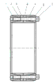
Fig. 1 is structural representation of the present utility model;
Fig. 2 is the right elevation of Fig. 1;
Fig. 3 is the schematic diagram that the utility model is implemented dismounting.
Embodiment
As Fig. 1, Fig. 2 and shown in Figure 3, bar shears expansion coupling sleeve in the present embodiment, it comprise encircle in apical ring 1, two outer shrouds 2,5, two 3,4 and base ring 6 form, wherein: encircle 3,4 in two and consist of back-to-back interior connecting sleeve, two outer shrouds 2,5 are located at respectively and encircle 3,4 side in two and form former and later two ring-type conical cavities, apical ring 1 and base ring 6 be located at respectively in two ring-type conical cavities and by Cock screw 7 with encircle in apical ring 1, two outer shrouds 2,5, two 3,4 and base ring 6 be installed together.Move back and unload in the screw that screw 8,9 is arranged on apical ring 1.
Above-mentioned interior ring 3, an end of 4 are the loop connecting body, and the cylindrical of interior ring 3,4 the other ends is conical surface, is provided with several screws on the loop connecting body, axially have an expansion joint 10 at interior ring.
Above-mentioned outer shroud 2,5 is ring bodies, and the inner circle of outer shroud is conical surface, axially has an expansion joint 11 at outer shroud.
Above-mentioned apical ring 1 and base ring 6 are ring bodies, cylindrical and the inner circle of apical ring 1 and base ring 6 are conical surface, the cylindrical conical surface of apical ring 1 and base ring 6 and the conical surface of outer shroud inner circle match, the inner circle conical surface of apical ring 1 and base ring 6 and the conical surface of interior ring cylindrical match, and are provided with several screws and screw hole on apical ring 1 and base ring 6.
Working procedure of the present utility model is: tighten Cock screw 7, get final product axial compression outer shroud 1, make it hold central shaft tightly by ring 3,4 in the effect compression of the conical surface, strut simultaneously outer shroud 2,5, be connected with the swelling of parts endoporus; When needing dismounting, first unclamp Cock screw 7, tighten to move back and unload screw 8,9 and expansion coupling sleeve can be drawn off from transmission part.
Claims (4)
1. bar shears expansion coupling sleeve, it comprises ring (3,4) and base ring (6) composition in apical ring (1), two outer shrouds (2,5), two, it is characterized in that: connecting sleeve in two, ring (3,4) consists of back-to-back, the side that two outer shrouds (2,5) are located at respectively in two ring (3,4) forms former and later two ring-type conical cavities, and apical ring (1) and base ring (6) are located at respectively in two ring-type conical cavities and will encircle (3,4) in apical ring (1), two outer shrouds (2,5), two and base ring (6) is installed together by screw.
2. bar shears expansion coupling sleeve according to claim 1, it is characterized in that: an end of described interior ring is the loop connecting body, the cylindrical of the interior ring the other end is conical surface, is provided with several screws on the loop connecting body, axially has an expansion joint (10) at interior ring.
3. bar shears expansion coupling sleeve according to claim 1, it is characterized in that: described outer shroud is ring bodies, the inner circle of outer shroud is conical surface, axially has an expansion joint (11) at outer shroud.
4. bar shears expansion coupling sleeve according to claim 1, it is characterized in that: described apical ring (1) and base ring (6) are ring bodies, cylindrical and the inner circle of apical ring (1) and base ring (6) are conical surface, the cylindrical conical surface of apical ring (1) and base ring (6) and the conical surface of outer shroud inner circle match, the inner circle conical surface of apical ring (1) and base ring (6) and the conical surface of interior ring cylindrical match, and are provided with several screws and screw hole on apical ring (1) and base ring (6).
Priority Applications (1)
| Application Number | Priority Date | Filing Date | Title |
|---|---|---|---|
| CN 201220609403 CN202937674U (en) | 2012-11-16 | 2012-11-16 | Expanding coupling sleeve for bar cutter |
Applications Claiming Priority (1)
| Application Number | Priority Date | Filing Date | Title |
|---|---|---|---|
| CN 201220609403 CN202937674U (en) | 2012-11-16 | 2012-11-16 | Expanding coupling sleeve for bar cutter |
Publications (1)
| Publication Number | Publication Date |
|---|---|
| CN202937674U true CN202937674U (en) | 2013-05-15 |
Family
ID=48321914
Family Applications (1)
| Application Number | Title | Priority Date | Filing Date |
|---|---|---|---|
| CN 201220609403 Expired - Fee Related CN202937674U (en) | 2012-11-16 | 2012-11-16 | Expanding coupling sleeve for bar cutter |
Country Status (1)
| Country | Link |
|---|---|
| CN (1) | CN202937674U (en) |
Cited By (1)
| Publication number | Priority date | Publication date | Assignee | Title |
|---|---|---|---|---|
| CN102937148A (en) * | 2012-11-16 | 2013-02-20 | 张新辉 | Tensioning connection sleeve for rod shearing machine |
-
2012
- 2012-11-16 CN CN 201220609403 patent/CN202937674U/en not_active Expired - Fee Related
Cited By (1)
| Publication number | Priority date | Publication date | Assignee | Title |
|---|---|---|---|---|
| CN102937148A (en) * | 2012-11-16 | 2013-02-20 | 张新辉 | Tensioning connection sleeve for rod shearing machine |
Similar Documents
| Publication | Publication Date | Title |
|---|---|---|
| CN201711557U (en) | Inner support device for petroleum casing pipe | |
| CN202228433U (en) | Hydraulic impeller loading and unloading tool for locomotive fan | |
| CN102937148A (en) | Tensioning connection sleeve for rod shearing machine | |
| CN102151712B (en) | Short screw connected expansion ring type fixed dummy block | |
| CN201487068U (en) | Quick-coupled shaft coupling with double taper sleeves | |
| CN103527650A (en) | Quick mounting and dismounting coupling | |
| CN203223486U (en) | Coupler | |
| CN202073941U (en) | Expansion coupling sleeve | |
| CN203239793U (en) | Wet-type multi-disc friction clutch | |
| CN206957967U (en) | A kind of removable axle sleeve for motor connection impeller | |
| CN218746009U (en) | Arm support shaft withdrawing device | |
| CN201220337Y (en) | Special-purpose tool for disassembling hydraulic coupling and brake disc | |
| CN204308213U (en) | A kind of horizontal Machining centers main axle structure | |
| CN201554734U (en) | Small-angle large-torque oil pressure disassembling expansion sleeve | |
| CN109277984A (en) | A tapered bearing disassembly tool | |
| CN103692191A (en) | Dismounting device for coupling flanges | |
| CN204628351U (en) | A kind of transmission shaft | |
| CN103398112A (en) | Clamping key type coupler | |
| CN203610944U (en) | Detachment device of coupling flange | |
| CN202017707U (en) | Taper rectangular spline centering connection structure for large-diameter concentric revolution body | |
| CN202284614U (en) | General connecting device for automobile drive axle running-in platform | |
| CN208074031U (en) | It is capable of the drum cog-wheel coupling of quick-replaceable cydariform tooth shaft | |
| CN204716391U (en) | The separation type hydraulic power station of a kind of engine output shaft connection set and application thereof | |
| CN202240743U (en) | Tool for external grinding of sleeve | |
| CN202690793U (en) | Telescoping type reducer provided with shrink disc |
Legal Events
| Date | Code | Title | Description |
|---|---|---|---|
| C14 | Grant of patent or utility model | ||
| GR01 | Patent grant | ||
| TR01 | Transfer of patent right |
Effective date of registration: 20180510 Address after: 043100 Xinjiang County Light Textile Industrial Park, Yuncheng, Shanxi Patentee after: Shanxi Daxin Transmission Technology Co., Ltd. Address before: 043100 Yuncheng city of Shanxi province Xinjiang Textile Industrial Park Patentee before: Zhang Xinhui |
|
| TR01 | Transfer of patent right | ||
| CF01 | Termination of patent right due to non-payment of annual fee |
Granted publication date: 20130515 Termination date: 20191116 |
|
| CF01 | Termination of patent right due to non-payment of annual fee |