A kind of reactive power automatic compensation device
Technical field
The utility model relates to power domain, more particularly, relates to a kind of reactive power automatic compensation device.
Background technology
Transformer station's centralized compensation and circuit dispersion compensation are the important component parts of reactive power compensation saving energy and decreasing loss work, and damage is fallen to its operational effect in the whole network and pressure regulation work has material impact.
Promote the installation high-voltage reactive power automatic compensation device, extremely significant saving energy and decreasing loss benefit is arranged, in addition, reactive power compensation can also improve the conveying capacity of circuit and equipment, improves the stability of operation of power networks, reduces the accident that causes because of circuit and equipment overload.
Because reactive power compensation can improve supply power voltage, so can also assist the low-voltage problem that solves rural power grids, epochmaking social benefit is arranged.
Market common VQC class compensation equipment fling-cut switch used, reactor, instrument transformers etc. are indoor type equipment, therefore general indoor type is pressed the design of switch cubicle pattern, outdoor type is pressed case modification formula design, seal very tight, the heat radiation deficiency, and the reactive-load compensation equipment caloric value is larger, and to cause the equipment operation failure rate higher because of heat dissipation problem.
Tradition reactive power compensation producer is all that buying capacitor, fling-cut switch, reactor, controller and casing and core component carry out simple assembling wiring, be subjected to current Element Technology horizontal constraints, often the complete sets of equipment volume is very large, and cost is higher, and is difficult to capacity expansion and upgrading after the equipment moulding.
For this reason, be badly in need of at present that a kind of integrated level is high, failure rate is low and capacity expansion and upgrading reactive power automatic compensation device easily.
The utility model content
In view of this, the utility model embodiment provides a kind of reactive power automatic compensation device, with realize that integrated level is high, failure rate is low and capacity expansion and upgrading purpose easily.
The utility model embodiment is achieved in that
A kind of reactive power automatic compensation device comprises capacitor unit;
Described capacitor unit comprises:
Instrument transformer reactor integrated device, fling-cut switch and shunt capacitor;
Described instrument transformer reactor integrated device, described fling-cut switch and the integrated encapsulation of described shunt capacitor;
Described fling-cut switch is the permanent magnetism fling-cut switch, and described permanent magnetism fling-cut switch adopts the oil-insulation encapsulation and is connected with reactor in instrument transformer reactor integrated device;
Instrument transformer in described instrument transformer reactor integrated device is the Luo Shi instrument transformer; Described Luo Shi instrument transformer is designed to the open type sampled current transformer.
Preferably, in the utility model embodiment, the described instrument transformer reactor integrated device in each described capacitor unit, described fling-cut switch and described shunt capacitor are a plurality of.
Preferably, in the utility model embodiment, the described instrument transformer reactor integrated device in each described capacitor unit, described fling-cut switch and described shunt capacitor are 3.
Preferably, in the utility model embodiment, described capacitor unit is a plurality of.
Can find out from above-mentioned technical scheme, in the utility model embodiment, by with instrument transformer reactor integrated device, fling-cut switch and the design of shunt capacitor integrative packaging, and after adopting the permanent magnetism fling-cut switch and the permanent magnetism fling-cut switch being adopted the oil-insulation encapsulation and the reactor in instrument transformer reactor integrated device be connected.So effectively reduced the volume of capacitor unit in the reactive power automatic compensation device, reduced the caloric value of capacitor unit, also make fling-cut switch have advantages of the just-off speed long service life, thereby reduced the failure rate of reactive power automatic compensation device.
In addition, in the utility model embodiment, the instrument transformer in instrument transformer reactor integrated device is the Luo Shi instrument transformer; So in the utility model embodiment in reactive power automatic compensation device capacitor unit signal output susceptibility high and dangerous without open circuit.
In addition, Luo Shi instrument transformer in the utility model embodiment is designed to the open type sampled current transformer, thereby do not need when mounted transversal, can install in any bar type of the optimal compensation point, thereby the fitness of the installation environment of the reactive power automatic compensation device that increases.
Because the reactive power automatic compensation device in the utility model embodiment can be made of any a plurality of capacitor units, so also make the capacity expansion and upgrading of reactive power automatic compensation device very convenient.
Description of drawings
In order to be illustrated more clearly in the utility model embodiment or technical scheme of the prior art, the below will do to introduce simply to the accompanying drawing of required use in embodiment or description of the Prior Art, apparently, accompanying drawing in the following describes is only embodiment more of the present utility model, for those of ordinary skills, under the prerequisite of not paying creative work, can also obtain according to these accompanying drawings other accompanying drawing.
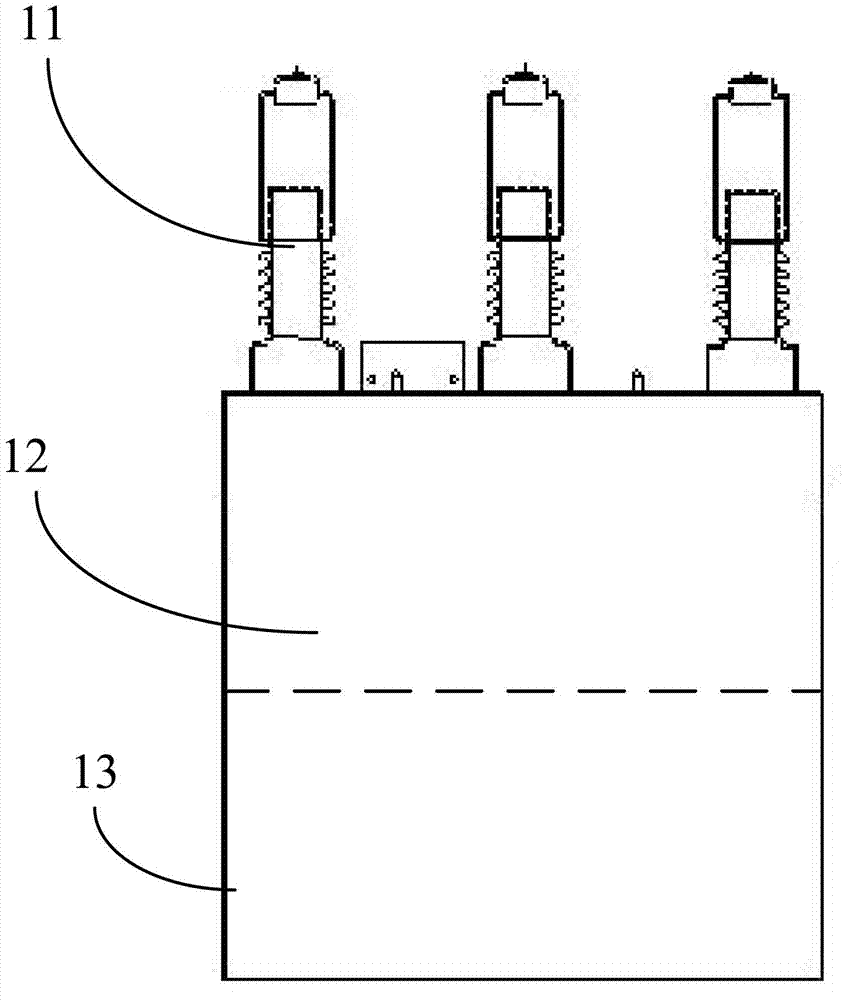
Fig. 1 is the structural representation of facing of the capacitor unit in reactive power automatic compensation device described in the utility model embodiment;
Fig. 2 is the side-looking structural representation of the capacitor unit in reactive power automatic compensation device described in the utility model embodiment;
Fig. 3 is the structural representation of reactive power automatic compensation device described in the utility model embodiment.
Embodiment
Below in conjunction with the accompanying drawing in the utility model embodiment, the technical scheme in the utility model embodiment is clearly and completely described, obviously, described embodiment is only the utility model part embodiment, rather than whole embodiment.Based on the embodiment in the utility model, those of ordinary skills are not making the every other embodiment that obtains under the creative work prerequisite, all belong to the scope of the utility model protection.
For realize that integrated level is high, failure rate is low and capacity expansion and upgrading purpose easily, as shown in Figure 1 to Figure 3, in the utility model embodiment, provide a kind of reactive power automatic compensation device, comprise capacitor unit 1;
Described capacitor unit 1 comprises instrument transformer reactor integrated device 11, fling-cut switch 12 and shunt capacitor 13;
In the utility model embodiment, adopt the design with instrument transformer and the integrated setting of reactor, thereby increased the integrated level of capacitor unit, further reduced the volume of capacitor unit; Wherein by the current limiting reactor in instrument transformer reactor integrated device 11, can effectively reduce input electric capacity to the impact of electrical network and equipment, thereby avoid causing the insulation breakdown of capacitor unit, and then also just increase the useful life of capacitor unit.
Instrument transformer reactor integrated device 11, fling-cut switch 12 and the integrated encapsulation of shunt capacitor 13;
For realizing the Highgrade integration of capacitor unit, on the basis with instrument transformer and the integrated setting of reactor, further, the utility model embodiment also is designed to integrative packaging with instrument transformer reactor integrated device 11, fling-cut switch 12 and shunt capacitor 13;
Wherein, fling-cut switch 12 is the permanent magnetism fling-cut switch, and the permanent magnetism fling-cut switch adopts the oil-insulation encapsulation and is connected with reactor in instrument transformer reactor integrated device 11;
Why adopt the permanent magnetism fling-cut switch, be because, the permanent magnetism fling-cut switch has had advantages of just-off speed and long service life, thereby not only solved the problem that the contactor series products is restriked, thumped and wear, also effectively improved the useful life of fling-cut switch, thereby also just effectively reduced the failure rate of reactive power automatic compensation device.
Because Luo Shi instrument transformer output susceptibility is high and dangerous without open circuit, so in the utility model embodiment, the instrument transformer in instrument transformer reactor integrated device 11 has adopted the Luo Shi instrument transformer; In addition, Luo Shi instrument transformer in the utility model embodiment also is designed to the open type sampled current transformer, thereby do not need when mounted transversal, can install in any bar type of the optimal compensation point, thereby the fitness of the installation environment of the reactive power automatic compensation device that increases.
Further, in the utility model embodiment, instrument transformer reactor integrated device 11, fling-cut switch 12 and shunt capacitor 13 in each capacitor unit 1 are a plurality of.That is to say, include the capacitor element that is consisted of by instrument transformer reactor integrated device 11, fling-cut switch 12 and shunt capacitance 13 devices of many groups in each capacitor unit 1, preferably, the number of capacitor element can be 3, that is, instrument transformer reactor integrated device 11, described fling-cut switch 12 and the shunt capacitor 13 in each capacitor unit is 3.
Capacitor unit 1 in the utility model embodiment can be for a plurality of, and configuration capacity as required is so also make the capacity expansion and upgrading of reactive power automatic compensation device very convenient.
In sum, in the utility model embodiment, by with instrument transformer reactor integrated device, fling-cut switch and the design of shunt capacitor integrative packaging, and after adopting the permanent magnetism fling-cut switch and the permanent magnetism fling-cut switch being adopted the oil-insulation encapsulation and the reactor in instrument transformer reactor integrated device be connected.So effectively reduced the volume of capacitor unit in the reactive power automatic compensation device, reduced the caloric value of capacitor unit, also make fling-cut switch have advantages of the just-off speed long service life, thereby reduced the failure rate of reactive power automatic compensation device.
In addition, in the utility model embodiment, the instrument transformer in instrument transformer reactor integrated device is the Luo Shi instrument transformer; So in the utility model embodiment in reactive power automatic compensation device capacitor unit signal output susceptibility high and dangerous without open circuit.
In addition, Luo Shi instrument transformer in the utility model embodiment is designed to the open type sampled current transformer, thereby do not need when mounted transversal, can install in any bar type of the optimal compensation point, thereby the fitness of the installation environment of the reactive power automatic compensation device that increases.
Because the reactive power automatic compensation device in the utility model embodiment can be made of any a plurality of capacitor units, so also make the capacity expansion and upgrading of reactive power automatic compensation device very convenient.
In this specification, each embodiment adopts the mode of going forward one by one to describe, and what each embodiment stressed is and the difference of other embodiment that between each embodiment, identical similar part is mutually referring to getting final product.
To the above-mentioned explanation of the disclosed embodiments, make this area professional and technical personnel can realize or use the utility model.Multiple modification to these embodiment will be apparent concerning those skilled in the art, and General Principle as defined herein can be in the situation that do not break away from spirit or scope of the present utility model, realization in other embodiments.Therefore, the utility model will can not be restricted to these embodiment shown in this article, but will meet the widest scope consistent with principle disclosed herein and features of novelty.