CN202926075U - Buffer capable of adjusting height of anti-bouncer wheel - Google Patents
Buffer capable of adjusting height of anti-bouncer wheel Download PDFInfo
- Publication number
- CN202926075U CN202926075U CN2012206208917U CN201220620891U CN202926075U CN 202926075 U CN202926075 U CN 202926075U CN 2012206208917 U CN2012206208917 U CN 2012206208917U CN 201220620891 U CN201220620891 U CN 201220620891U CN 202926075 U CN202926075 U CN 202926075U
- Authority
- CN
- China
- Prior art keywords
- wheel
- base
- jump
- bouncer
- height
- Prior art date
- Legal status (The legal status is an assumption and is not a legal conclusion. Google has not performed a legal analysis and makes no representation as to the accuracy of the status listed.)
- Expired - Lifetime
Links
- 238000003466 welding Methods 0.000 claims description 3
- 230000009286 beneficial effect Effects 0.000 abstract description 2
- 238000004519 manufacturing process Methods 0.000 abstract description 2
- 238000009434 installation Methods 0.000 description 3
- 238000010586 diagram Methods 0.000 description 2
- 230000000694 effects Effects 0.000 description 2
- 239000012467 final product Substances 0.000 description 2
- 238000010276 construction Methods 0.000 description 1
- 238000005516 engineering process Methods 0.000 description 1
- 230000003116 impacting effect Effects 0.000 description 1
- 238000002955 isolation Methods 0.000 description 1
- 230000009191 jumping Effects 0.000 description 1
- 238000005259 measurement Methods 0.000 description 1
- 238000000034 method Methods 0.000 description 1
- 238000012986 modification Methods 0.000 description 1
- 230000004048 modification Effects 0.000 description 1
- 230000001105 regulatory effect Effects 0.000 description 1
- 238000003756 stirring Methods 0.000 description 1
Images


Classifications
-
- E—FIXED CONSTRUCTIONS
- E05—LOCKS; KEYS; WINDOW OR DOOR FITTINGS; SAFES
- E05F—DEVICES FOR MOVING WINGS INTO OPEN OR CLOSED POSITION; CHECKS FOR WINGS; WING FITTINGS NOT OTHERWISE PROVIDED FOR, CONCERNED WITH THE FUNCTIONING OF THE WING
- E05F1/00—Closers or openers for wings, not otherwise provided for in this subclass
- E05F1/08—Closers or openers for wings, not otherwise provided for in this subclass spring-actuated, e.g. for horizontally sliding wings
- E05F1/16—Closers or openers for wings, not otherwise provided for in this subclass spring-actuated, e.g. for horizontally sliding wings for sliding wings
-
- E—FIXED CONSTRUCTIONS
- E05—LOCKS; KEYS; WINDOW OR DOOR FITTINGS; SAFES
- E05F—DEVICES FOR MOVING WINGS INTO OPEN OR CLOSED POSITION; CHECKS FOR WINGS; WING FITTINGS NOT OTHERWISE PROVIDED FOR, CONCERNED WITH THE FUNCTIONING OF THE WING
- E05F5/00—Braking devices, e.g. checks; Stops; Buffers
- E05F5/003—Braking devices, e.g. checks; Stops; Buffers for sliding wings
-
- E—FIXED CONSTRUCTIONS
- E05—LOCKS; KEYS; WINDOW OR DOOR FITTINGS; SAFES
- E05F—DEVICES FOR MOVING WINGS INTO OPEN OR CLOSED POSITION; CHECKS FOR WINGS; WING FITTINGS NOT OTHERWISE PROVIDED FOR, CONCERNED WITH THE FUNCTIONING OF THE WING
- E05F5/00—Braking devices, e.g. checks; Stops; Buffers
- E05F5/02—Braking devices, e.g. checks; Stops; Buffers specially for preventing the slamming of swinging wings during final closing movement, e.g. jamb stops
- E05F5/027—Braking devices, e.g. checks; Stops; Buffers specially for preventing the slamming of swinging wings during final closing movement, e.g. jamb stops with closing action
-
- E—FIXED CONSTRUCTIONS
- E05—LOCKS; KEYS; WINDOW OR DOOR FITTINGS; SAFES
- E05Y—INDEXING SCHEME ASSOCIATED WITH SUBCLASSES E05D AND E05F, RELATING TO CONSTRUCTION ELEMENTS, ELECTRIC CONTROL, POWER SUPPLY, POWER SIGNAL OR TRANSMISSION, USER INTERFACES, MOUNTING OR COUPLING, DETAILS, ACCESSORIES, AUXILIARY OPERATIONS NOT OTHERWISE PROVIDED FOR, APPLICATION THEREOF
- E05Y2201/00—Constructional elements; Accessories therefor
- E05Y2201/60—Suspension or transmission members; Accessories therefor
- E05Y2201/606—Accessories therefor
- E05Y2201/61—Cooperation between suspension or transmission members
- E05Y2201/612—Cooperation between suspension or transmission members between carriers and rails
- E05Y2201/614—Anti-derailing means
-
- E—FIXED CONSTRUCTIONS
- E05—LOCKS; KEYS; WINDOW OR DOOR FITTINGS; SAFES
- E05Y—INDEXING SCHEME ASSOCIATED WITH SUBCLASSES E05D AND E05F, RELATING TO CONSTRUCTION ELEMENTS, ELECTRIC CONTROL, POWER SUPPLY, POWER SIGNAL OR TRANSMISSION, USER INTERFACES, MOUNTING OR COUPLING, DETAILS, ACCESSORIES, AUXILIARY OPERATIONS NOT OTHERWISE PROVIDED FOR, APPLICATION THEREOF
- E05Y2600/00—Mounting or coupling arrangements for elements provided for in this subclass
- E05Y2600/10—Adjustable
- E05Y2600/12—Adjustable by manual operation
-
- E—FIXED CONSTRUCTIONS
- E05—LOCKS; KEYS; WINDOW OR DOOR FITTINGS; SAFES
- E05Y—INDEXING SCHEME ASSOCIATED WITH SUBCLASSES E05D AND E05F, RELATING TO CONSTRUCTION ELEMENTS, ELECTRIC CONTROL, POWER SUPPLY, POWER SIGNAL OR TRANSMISSION, USER INTERFACES, MOUNTING OR COUPLING, DETAILS, ACCESSORIES, AUXILIARY OPERATIONS NOT OTHERWISE PROVIDED FOR, APPLICATION THEREOF
- E05Y2600/00—Mounting or coupling arrangements for elements provided for in this subclass
- E05Y2600/60—Mounting or coupling members; Accessories therefor
- E05Y2600/626—Plates or brackets
-
- E—FIXED CONSTRUCTIONS
- E05—LOCKS; KEYS; WINDOW OR DOOR FITTINGS; SAFES
- E05Y—INDEXING SCHEME ASSOCIATED WITH SUBCLASSES E05D AND E05F, RELATING TO CONSTRUCTION ELEMENTS, ELECTRIC CONTROL, POWER SUPPLY, POWER SIGNAL OR TRANSMISSION, USER INTERFACES, MOUNTING OR COUPLING, DETAILS, ACCESSORIES, AUXILIARY OPERATIONS NOT OTHERWISE PROVIDED FOR, APPLICATION THEREOF
- E05Y2800/00—Details, accessories and auxiliary operations not otherwise provided for
- E05Y2800/20—Combinations of elements
- E05Y2800/205—Combinations of elements forming a unit
-
- E—FIXED CONSTRUCTIONS
- E05—LOCKS; KEYS; WINDOW OR DOOR FITTINGS; SAFES
- E05Y—INDEXING SCHEME ASSOCIATED WITH SUBCLASSES E05D AND E05F, RELATING TO CONSTRUCTION ELEMENTS, ELECTRIC CONTROL, POWER SUPPLY, POWER SIGNAL OR TRANSMISSION, USER INTERFACES, MOUNTING OR COUPLING, DETAILS, ACCESSORIES, AUXILIARY OPERATIONS NOT OTHERWISE PROVIDED FOR, APPLICATION THEREOF
- E05Y2800/00—Details, accessories and auxiliary operations not otherwise provided for
- E05Y2800/20—Combinations of elements
- E05Y2800/23—Combinations of elements of elements of different categories
- E05Y2800/24—Combinations of elements of elements of different categories of springs and brakes
-
- E—FIXED CONSTRUCTIONS
- E05—LOCKS; KEYS; WINDOW OR DOOR FITTINGS; SAFES
- E05Y—INDEXING SCHEME ASSOCIATED WITH SUBCLASSES E05D AND E05F, RELATING TO CONSTRUCTION ELEMENTS, ELECTRIC CONTROL, POWER SUPPLY, POWER SIGNAL OR TRANSMISSION, USER INTERFACES, MOUNTING OR COUPLING, DETAILS, ACCESSORIES, AUXILIARY OPERATIONS NOT OTHERWISE PROVIDED FOR, APPLICATION THEREOF
- E05Y2900/00—Application of doors, windows, wings or fittings thereof
- E05Y2900/20—Application of doors, windows, wings or fittings thereof for furniture, e.g. cabinets
Landscapes
- Support Devices For Sliding Doors (AREA)
Abstract
The utility model provides a buffer capable of adjusting the height of an anti-bouncer wheel. The buffer comprises a bottom board and a resetting device arranged on the bottom board, and is characterized in that the anti-bouncer wheel is further arranged on the bottom board, and is rotatably mounted at the top end of a bracket board; the tail end of the bracket board is movably hinged with a base; and an adjusting screw is screwed on the base and is abutted against the bottom of the bracket board. The buffer provided by the utility model has the beneficial effects that 1) the structure is simple, the production cost is low, and the market competitiveness is improved; 2) the anti-bouncer wheel is mounted on the traditional buffer, so that a derailment phenomenon caused by impact when a door or a window is closed can be prevented; and 3) the height of the anti-bouncer wheel can be randomly adjusted, so that the buffer can be applicable to various door frames, and the mounting difficulty and the requirement on size precision can be reduced.
Description
Technical field
The utility model relates to the snubber that a kind of flat sliding door uses, and specifically a kind ofly regulates anti-jump snubber of taking turns height.
Background technology
At present; generally all used isolation damper on the flat sliding door of furniture; and at the shifting block of stirring damper of the interior installation of getting on the right track of flat sliding door; when the flat sliding door of promotion keeps to the side; shifting block is stuck on the movable part of damper; driving flat sliding door slowly moves; until rest in the frame side of door; cushioning effect due to damper; make flat sliding door near not bumping in doorframe, avoid sending noise because of collision, or even protect the flat sliding door can be not therefore and damaged in collision; therefore, quite be subjected to liking of customer.Yet when people overexert or strength the is excessive flat sliding door of promotion, the inertia of flat sliding door is larger due to this moment, the moment that shifting block coordinates with damper, the phenomenon that one side of flat sliding door can occur jumping produces noise, also easily makes the return pulley of flat sliding door break away from track when serious.Therefore be necessary prior art is made further modification and perfection.
The utility model content
The purpose of this utility model is the shortcoming that exists in order to overcome prior art, provides a kind of simple and reasonable, and safe ready makes the steadily quiet operation of flat sliding door, and the anti-jump snubber of taking turns height of regulating easy to adjust is installed.
The utility model is realized with the following methods: a kind of regulate anti-jump take turns the height snubber, it comprises base plate and is located at resetting means on base plate, it is characterized in that: also be provided with anti-jump the wheel on described base plate, described anti-jump the wheel is installed in rotation on the supporting plate top, the supporting plate tail end is movably articulated on base, is bolted with set screw on described base and is pressed on bottom supporting plate.
Described supporting plate is movably articulated on base by rotating shaft, in described rotating shaft, pre-compressed spring is installed.
The stressed pin of described pre-compressed spring two is respectively by being pressed on base and supporting plate.
Described anti-jump the wheel is plastic roller.
Described base is fixed on base plate by welding or riveted joint.
The beneficial effects of the utility model are: 1) simple in structure, cost of production is low, improves the market competitiveness.2) the anti-jump wheel is installed on conventional buffer, can prevents that door and window is subject to impacting the generation derailment occurring when closing.3) but anti-jumply take turns the height free adjustment, use therefore can adapt to various doorframes, reduce installation difficulty and to the dimensional requirement precision.
Description of drawings
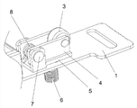
Fig. 1 is this utility structure schematic diagram.
Fig. 2 is part-structure enlarged drawing in the utility model Fig. 1.
Fig. 3 is the anti-jump wheel construction schematic diagram of the utility model.
The specific embodiment
Below in conjunction with accompanying drawing, the utility model is made concrete further instruction.A kind of regulate anti-jump take turns the height snubber, it comprises base plate 1 and is located at resetting means 2 on base plate, it is characterized in that: also be provided with on described base plate 1 and anti-jumply take turns 3, describedly anti-jumply take turns 3 and be installed in rotation on supporting plate 4 tops, supporting plate 4 tail ends are movably articulated on base 5, are bolted with set screw 6 on described base 5 and are pressed on supporting plate 4 bottoms.
Described supporting plate 4 is movably articulated on base by rotating shaft 7, in described rotating shaft 7, pre-compressed spring 8 is installed, and wherein pivot structure can directly replace getting final product with rivet.
By being pressed on base 5 and supporting plate 4, wherein pre-compressed spring is torsion spring to 8 liang of stressed pin of described pre-compressed spring respectively.
Describedly anti-jumply take turns 3 for plastic roller.
Described base 5 is fixed on base plate 1 by welding or riveted joint.
The specific embodiment: in the utility model, during installation, after first measuring doorframe and installing with the distance on guide rail top, then set screw 6 make anti-jump take turns and base plate between distance equal or slightly less than the distance of previous measurement.At last with snubber with after doorframe is connected, doorframe is put into guide rail gets final product.In the utility model, the anti-jump wheel of installing on snubber utilizes anti-jump the wheel to withstand in guide rail, and the restriction doorframe is the gap of activity upwards, plays anti creep performance.
Obviously, above-described embodiment is only for example clearly is described, and is not the restriction to embodiment.For those of ordinary skill in the field, can also make other changes in different forms on the basis of the above description.Here need not also can't give all embodiments exhaustive.And the apparent variation of being extended out thus or change still are among the protection domain of claims of the invention.
Claims (5)
1. can regulate anti-jump snubber of taking turns height for one kind, it comprises base plate (1) and is located at resetting means (2) on base plate, it is characterized in that: also be provided with anti-jump wheel the (3) on described base plate (1), described anti-jump wheel the (3) is installed in rotation on supporting plate (4) top, supporting plate (4) tail end is movably articulated on base (5), is bolted with set screw (6) on described base (5) and is pressed on bottom supporting plate (4).
According to claim 1 regulate anti-jump take turns the height snubber, it is characterized in that: described supporting plate (4) is movably articulated on base by rotating shaft (7), and pre-compressed spring (8) is installed in described rotating shaft (7).
3. according to claim 2ly regulate anti-jump snubber of taking turns height, it is characterized in that: described pre-compressed spring (8) two stressed pin are respectively by being pressed on base (5) and supporting plate (4).
4. according to claim 1ly regulate anti-jump snubber of taking turns height, it is characterized in that: described anti-jump wheel the (3) is for plastic roller.
According to claim 1 regulate anti-jump take turns the height snubber, it is characterized in that: described base (5) by the welding or the riveted joint be fixed on base plate (1).
Priority Applications (1)
| Application Number | Priority Date | Filing Date | Title |
|---|---|---|---|
| CN2012206208917U CN202926075U (en) | 2012-11-22 | 2012-11-22 | Buffer capable of adjusting height of anti-bouncer wheel |
Applications Claiming Priority (1)
| Application Number | Priority Date | Filing Date | Title |
|---|---|---|---|
| CN2012206208917U CN202926075U (en) | 2012-11-22 | 2012-11-22 | Buffer capable of adjusting height of anti-bouncer wheel |
Publications (1)
| Publication Number | Publication Date |
|---|---|
| CN202926075U true CN202926075U (en) | 2013-05-08 |
Family
ID=48216048
Family Applications (1)
| Application Number | Title | Priority Date | Filing Date |
|---|---|---|---|
| CN2012206208917U Expired - Lifetime CN202926075U (en) | 2012-11-22 | 2012-11-22 | Buffer capable of adjusting height of anti-bouncer wheel |
Country Status (1)
| Country | Link |
|---|---|
| CN (1) | CN202926075U (en) |
Cited By (4)
| Publication number | Priority date | Publication date | Assignee | Title |
|---|---|---|---|---|
| CN104763260A (en) * | 2014-01-02 | 2015-07-08 | 苏州升德精密电气有限公司 | Anti-jump limiting upper wheel for door body |
| CN104847205A (en) * | 2015-05-21 | 2015-08-19 | 苏州升德精密电气有限公司 | Tripping-prevention positioning structure for door-return buffering device |
| CN110259312A (en) * | 2019-07-30 | 2019-09-20 | 苏州升德精密电气有限公司 | A kind of light-duty sliding door is anti-to jump onto wheel |
| CN110439411A (en) * | 2019-09-09 | 2019-11-12 | 苏州升德精密电气有限公司 | A kind of anti-jump sliding door damper |
-
2012
- 2012-11-22 CN CN2012206208917U patent/CN202926075U/en not_active Expired - Lifetime
Cited By (5)
| Publication number | Priority date | Publication date | Assignee | Title |
|---|---|---|---|---|
| CN104763260A (en) * | 2014-01-02 | 2015-07-08 | 苏州升德精密电气有限公司 | Anti-jump limiting upper wheel for door body |
| CN104763260B (en) * | 2014-01-02 | 2017-02-22 | 苏州升德精密电气有限公司 | Anti-jump limiting upper wheel for door body |
| CN104847205A (en) * | 2015-05-21 | 2015-08-19 | 苏州升德精密电气有限公司 | Tripping-prevention positioning structure for door-return buffering device |
| CN110259312A (en) * | 2019-07-30 | 2019-09-20 | 苏州升德精密电气有限公司 | A kind of light-duty sliding door is anti-to jump onto wheel |
| CN110439411A (en) * | 2019-09-09 | 2019-11-12 | 苏州升德精密电气有限公司 | A kind of anti-jump sliding door damper |
Similar Documents
| Publication | Publication Date | Title |
|---|---|---|
| ATE505612T1 (en) | DRIVE FOR SLIDING DOORS AND WINDOWS | |
| CN204212587U (en) | A kind of Door suspension upper internal door pulley assembly | |
| CN102619425B (en) | Lower movable pulley assembly of horizontal sliding door | |
| CN201874414U (en) | Side window of driver's cab of railway passenger car | |
| CN205012819U (en) | Be used for door and window to prevent falling three -dimensional adjustable buffering hinge in angle | |
| CN202467441U (en) | Anti-bouncer of sliding door | |
| CN201738717U (en) | Sliding door anti-bouncing structure with damper | |
| CN204899543U (en) | Prevent jumping guider with adjustable push -pull sliding door | |
| CN207829722U (en) | A kind of linkage buffering sliding door | |
| CN204139822U (en) | A kind of can block piece on the sliding sliding door of Fast Installation | |
| CN202194484U (en) | Double-subwheel lower roller | |
| CN203050332U (en) | Pulley | |
| CN203452517U (en) | Flat sliding door buffer with adjustable anti-tripping wheel | |
| CN204212593U (en) | A kind of Door suspension lower whorl buffer limit assembly | |
| CN203796051U (en) | Novel sliding door damper | |
| CN202850720U (en) | Buffer for sliding door of bathroom | |
| CN202417141U (en) | Novel guide mechanism for hanging sliding door | |
| CN202810449U (en) | Guide sliding rail for multi-door left and right buffering opening and closing | |
| CN202578287U (en) | Anti-derail wheel adjustable buffer for flat door | |
| CN203129799U (en) | Friction hinge | |
| CN203755876U (en) | Novel flat sliding door antibouncer with cushion cylinder | |
| CN203626458U (en) | Second-stage force buffer door hinge | |
| CN104989216B (en) | A kind of electronic iron gate of rack drives | |
| CN210289507U (en) | Anti-derailing structure of sliding door | |
| CN205522656U (en) | Dead device of anti -sticking of hydraulic press automatic rising guardrail |
Legal Events
| Date | Code | Title | Description |
|---|---|---|---|
| C14 | Grant of patent or utility model | ||
| GR01 | Patent grant | ||
| CX01 | Expiry of patent term | ||
| CX01 | Expiry of patent term |
Granted publication date: 20130508 |