CN202923434U - Collision safety seat for motor vehicle - Google Patents
Collision safety seat for motor vehicle Download PDFInfo
- Publication number
- CN202923434U CN202923434U CN 201220642164 CN201220642164U CN202923434U CN 202923434 U CN202923434 U CN 202923434U CN 201220642164 CN201220642164 CN 201220642164 CN 201220642164 U CN201220642164 U CN 201220642164U CN 202923434 U CN202923434 U CN 202923434U
- Authority
- CN
- China
- Prior art keywords
- inverted
- shaped guide
- guide rod
- headrest
- motor vehicle
- Prior art date
- Legal status (The legal status is an assumption and is not a legal conclusion. Google has not performed a legal analysis and makes no representation as to the accuracy of the status listed.)
- Expired - Fee Related
Links
- 206010019196 Head injury Diseases 0.000 abstract description 4
- 238000010586 diagram Methods 0.000 description 3
- 230000006378 damage Effects 0.000 description 2
- 230000009286 beneficial effect Effects 0.000 description 1
- 230000007547 defect Effects 0.000 description 1
- 230000005489 elastic deformation Effects 0.000 description 1
- 238000000034 method Methods 0.000 description 1
Images


Landscapes
- Seats For Vehicles (AREA)
Abstract
本实用新型属机动车安全装置,涉及一种机动车碰撞安全座椅。所述安全座椅,包括座椅头枕、座椅靠背,还包括一倒U形导杆,所述倒U形导杆包括两端的竖直杆和中间的水平杆;倒U形导杆两端竖直杆插入靠背中;头枕通过头枕骨架中的左、右两纵板连接在倒U形导杆水平杆上;左、右两纵板间有一转簧,转簧套装固定于倒U形导杆的水平杆上,转簧两端分别固定于左、右两纵板上。在机动车正面碰撞中,能缓冲后排乘客头部与前排座椅头枕的碰撞,有效减轻后排乘客头部受到的伤害。
The utility model belongs to a motor vehicle safety device and relates to a motor vehicle collision safety seat. The safety seat includes a seat headrest, a seat back, and an inverted U-shaped guide rod, and the inverted U-shaped guide rod includes vertical rods at two ends and a horizontal rod in the middle; The end vertical rod is inserted into the backrest; the headrest is connected to the horizontal rod of the inverted U-shaped guide rod through the left and right longitudinal plates in the headrest frame; there is a rotating spring between the left and right longitudinal plates, and the rotating spring set is fixed on the inverted On the horizontal rod of the U-shaped guide rod, the two ends of the torsion spring are respectively fixed on the left and right vertical plates. In the frontal collision of a motor vehicle, it can buffer the collision between the heads of the rear passengers and the headrests of the front seats, effectively reducing the head injuries of the rear passengers.
Description
技术领域technical field
本实用新型属机动车安全装置,用于保护乘客安全,特别涉及一种保护后排乘客头部安全的机动车碰撞安全座椅。The utility model belongs to a motor vehicle safety device, which is used for protecting the safety of passengers, in particular to a motor vehicle collision safety seat for protecting the head safety of rear passengers.
背景技术Background technique
机动车座椅是乘员保护的重要组成部分。在机动车正面碰撞中,受安全带约束的乘客在惯性力的作用下会向前冲撞,后排乘客的头部会撞击到前排座椅头枕上。通常,普通座椅的头枕是固定连接在座椅上部的,在撞击力的作用下不能向前产生位移,因此,前排头枕会对后排乘客头部产生伤害。Motor vehicle seats are an important part of occupant protection. In a frontal collision of a motor vehicle, passengers restrained by seat belts will rush forward under the action of inertial force, and the heads of the rear passengers will hit the headrests of the front seats. Usually, the headrests of ordinary seats are fixedly connected to the upper part of the seat, and cannot be displaced forward under the impact force. Therefore, the front row of headrests will cause damage to the heads of the rear passengers.
实用新型内容Utility model content
本实用新型的目的在于克服现有机动车座椅的缺陷而提供一种机动车碰撞安全座椅,在机动车正面碰撞时能对后排乘客头部进行保护。The purpose of the utility model is to overcome the defects of the existing motor vehicle seats and provide a motor vehicle collision safety seat, which can protect the heads of rear passengers when the motor vehicle collides head-on.
本实用新型采用的技术方案是:一种机动车碰撞安全座椅,包括座椅头枕、座椅靠背,还包括一倒U形导杆,所述倒U形导杆包括两端的竖直杆和中间的水平杆;倒U形导杆两端竖直杆插入靠背中;头枕通过头枕骨架中的左、右两纵板连接在倒U形导杆水平杆上;左、右两纵板间有一转簧,转簧套装固定于倒U形导杆的水平杆上,转簧两端分别固定于左、右两纵板上。The technical solution adopted by the utility model is: a motor vehicle collision safety seat, including a seat headrest, a seat back, and an inverted U-shaped guide rod, and the inverted U-shaped guide rod includes vertical rods at both ends and the horizontal rod in the middle; the vertical rods at both ends of the inverted U-shaped guide rod are inserted into the backrest; the headrest is connected to the horizontal rod of the inverted U-shaped guide rod through the left and right longitudinal plates in the headrest frame; There is a rotary spring between the plates, and the rotary spring suit is fixed on the horizontal bar of the inverted U-shaped guide rod, and the two ends of the rotary spring are respectively fixed on the left and right vertical plates.
所述两纵板突出于头枕下部,并与倒U形导杆的水平杆间隙连接。两纵板上各设有小孔用于固定转簧。The two longitudinal plates protrude from the lower part of the headrest, and are gap-connected with the horizontal bar of the inverted U-shaped guide bar. Each of the two longitudinal plates is provided with a small hole for fixing the rotary spring.
本实用新型的有益效果在于:在机动车正面碰撞中,当后排乘客头部与前排座椅头枕碰撞,并且碰撞强度较大,导致后排乘客头部伤害值(HIC)超过1000时,能缓冲后排乘客头部与前排座椅头枕的碰撞,有效减轻后排乘客头部受到的伤害。The beneficial effect of the utility model is that: in the frontal collision of the motor vehicle, when the head of the rear passenger collides with the headrest of the front seat, and the collision intensity is relatively large, causing the head injury value (HIC) of the rear passenger to exceed 1000 , It can buffer the collision between the heads of the rear passengers and the headrests of the front seats, effectively reducing the head injuries of the rear passengers.
附图说明Description of drawings
以下结合附图和具体实施方式对本实用新型作进一步详细说明。The utility model will be described in further detail below in conjunction with the accompanying drawings and specific embodiments.
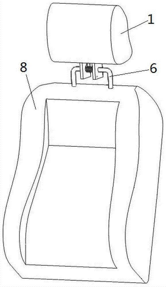
图1是本实用新型整体结构示意图;Fig. 1 is a schematic diagram of the overall structure of the utility model;
图2是本实用新型中头枕骨架、转簧以及倒U形导杆装配示意图;Fig. 2 is a schematic diagram of the assembly of the headrest frame, the rotating spring and the inverted U-shaped guide rod in the utility model;
图3是图2的正视图;Fig. 3 is the front view of Fig. 2;
图4是本实用新型中头枕骨架结构示意图;Fig. 4 is a schematic diagram of the skeleton structure of the headrest in the utility model;
图中:1.头枕;2.头枕骨架;3.左、右两纵板;4.圆孔;5.小孔;6.倒U形导杆;7.转簧;8.靠背。In the figure: 1. Headrest; 2. Headrest frame; 3. Left and right vertical plates; 4. Round hole; 5. Small hole; 6. Inverted U-shaped guide rod; 7. Rotary spring; 8. Backrest.
具体实施方式Detailed ways
如图1至图4所示,本实用新型的最上端为头枕1,头枕1下部为倒U形导杆6,头枕1通过头枕骨架2中的左、右两纵板3与倒U形导杆6连接。倒U形导杆6下部为靠背8,倒U形导杆6的两个竖直杆插入靠背8中。左、右两纵板3突出于头枕1下端。倒U形导杆6中的一个水平杆间隙穿过左、右两纵板3中的圆孔4,这样水平杆与两纵板3形成转动铰链,两纵板3可绕倒U形导杆6中的水平杆转动。在左、右两纵板3间有一转簧7。转簧7套装固定于倒U形导杆6的水平杆上。转簧7的两端分别卡在左、右两纵板3的小孔5内。As shown in Figures 1 to 4, the uppermost end of the utility model is a
在机动车正面碰撞中,车内受安全带约束的乘客在惯性力作用下向前位移,当后排乘客的头部与前排座椅头枕1碰撞,并且碰撞强度较大,导致后排乘客头部伤害值(HIC)超过1000时,转簧7的两端在左、右两纵板3的压力作用下发生扭转弹性变形,这样左、右两纵板3就绕倒U形导杆6中的水平杆向前转动一定角度,同时前排座椅头枕1向前转动一定角度,缓冲后排乘客头部与前排座椅头枕1的碰撞,有效减轻后排乘客头部受到的伤害。当碰撞结束后,车内乘客在安全带约束下向后位移,左、右两纵板3失去后排乘客碰撞力的作用,不再给转簧7施加压力。此时转簧7两端恢复原有形状,反作用于两纵板3,使其绕倒U形导杆6中的水平杆恢复竖直状态,同时前排座椅头枕1恢复原来位置,正常保护向后位移的前排乘客颈部。In a frontal collision of a motor vehicle, passengers restrained by seat belts in the vehicle move forward under the action of inertial force. When the passenger's head injury value (HIC) exceeds 1000, the two ends of the
Claims (3)
Priority Applications (1)
| Application Number | Priority Date | Filing Date | Title |
|---|---|---|---|
| CN 201220642164 CN202923434U (en) | 2012-11-29 | 2012-11-29 | Collision safety seat for motor vehicle |
Applications Claiming Priority (1)
| Application Number | Priority Date | Filing Date | Title |
|---|---|---|---|
| CN 201220642164 CN202923434U (en) | 2012-11-29 | 2012-11-29 | Collision safety seat for motor vehicle |
Publications (1)
| Publication Number | Publication Date |
|---|---|
| CN202923434U true CN202923434U (en) | 2013-05-08 |
Family
ID=48213428
Family Applications (1)
| Application Number | Title | Priority Date | Filing Date |
|---|---|---|---|
| CN 201220642164 Expired - Fee Related CN202923434U (en) | 2012-11-29 | 2012-11-29 | Collision safety seat for motor vehicle |
Country Status (1)
| Country | Link |
|---|---|
| CN (1) | CN202923434U (en) |
Cited By (2)
| Publication number | Priority date | Publication date | Assignee | Title |
|---|---|---|---|---|
| CN103832300A (en) * | 2014-02-07 | 2014-06-04 | 江苏大学 | Motor vehicle safety seat |
| CN107826136A (en) * | 2017-11-06 | 2018-03-23 | 北京交通大学 | Car seat and its design method |
-
2012
- 2012-11-29 CN CN 201220642164 patent/CN202923434U/en not_active Expired - Fee Related
Cited By (4)
| Publication number | Priority date | Publication date | Assignee | Title |
|---|---|---|---|---|
| CN103832300A (en) * | 2014-02-07 | 2014-06-04 | 江苏大学 | Motor vehicle safety seat |
| CN103832300B (en) * | 2014-02-07 | 2016-08-31 | 江苏大学 | Safety seat for motor vehicle |
| CN107826136A (en) * | 2017-11-06 | 2018-03-23 | 北京交通大学 | Car seat and its design method |
| CN107826136B (en) * | 2017-11-06 | 2020-01-03 | 北京交通大学 | Safety seat for a vehicle and method for designing the same |
Similar Documents
| Publication | Publication Date | Title |
|---|---|---|
| CN103832300B (en) | Safety seat for motor vehicle | |
| CN107826136B (en) | Safety seat for a vehicle and method for designing the same | |
| CN204367924U (en) | A kind of energy-absorption type child safety seat | |
| CN108928272B (en) | Anti-submersion method and device for automobile rear row | |
| CN204774762U (en) | Vehicle and vehicle seat and seat structure | |
| CN108909555B (en) | Seat device capable of preventing whiplash injury and vehicle | |
| CN109130976A (en) | Safety chair seats of car for children | |
| CN103273861B (en) | Motor vehicle front collision safety seat | |
| CN111873879A (en) | Automobile headrest structure | |
| CN104553913B (en) | With the car crass active safe headrest device for letting out force mechanisms | |
| CN204488582U (en) | A kind of anti-flogging device for automobile seat, automotive seat and automobile | |
| CN103303170B (en) | Multifunctional motor vehicle collision safety seat | |
| CN202378733U (en) | Motor vehicle collision safety seat | |
| CN102555862A (en) | Seat mounting structure | |
| CN101905664B (en) | Anti-rear collision neck protection seat | |
| CN107804204B (en) | Safety backrest of motor vehicle | |
| CN106828230A (en) | A kind of safety seat for motor vehicle | |
| CN201553055U (en) | car headrest device | |
| CN106828221A (en) | Safety seat for motor vehicle | |
| CN202345441U (en) | Seat energy-absorption anti-whiplash system | |
| CN202782769U (en) | rear seat | |
| CN107826008B (en) | Motor vehicle safety backrest | |
| CN105667361B (en) | A kind of collision of motor-driven vehicles safety backrest | |
| CN204801567U (en) | Prevent whipping active back of car seat | |
| CN104494483A (en) | Vehicle seat preventing whiplash injury |
Legal Events
| Date | Code | Title | Description |
|---|---|---|---|
| C14 | Grant of patent or utility model | ||
| GR01 | Patent grant | ||
| CF01 | Termination of patent right due to non-payment of annual fee |
Granted publication date: 20130508 Termination date: 20151129 |