CN202915506U - Novel air returning system for plant - Google Patents
Novel air returning system for plant Download PDFInfo
- Publication number
- CN202915506U CN202915506U CN 201220663823 CN201220663823U CN202915506U CN 202915506 U CN202915506 U CN 202915506U CN 201220663823 CN201220663823 CN 201220663823 CN 201220663823 U CN201220663823 U CN 201220663823U CN 202915506 U CN202915506 U CN 202915506U
- Authority
- CN
- China
- Prior art keywords
- return air
- dust filter
- exhaust fan
- air system
- workshop
- Prior art date
- Legal status (The legal status is an assumption and is not a legal conclusion. Google has not performed a legal analysis and makes no representation as to the accuracy of the status listed.)
- Expired - Fee Related
Links
Images

Landscapes
- Ventilation (AREA)
Abstract
一种新型厂房回风系统,包括风力管道,风力管道包括大径端、弯管端和与风力管道连通的风口段,回风系统还包括设置在大径端的滤尘器和设置在风口段的抽风机。本实用新型的有益效果在于:本实用新型设计的目的在于实现厂房良好的温度和湿度的控制,在回风系统中使用了滤尘器、抽风机和管道,这样通过滤尘器滤风后的热风即可排到车间内、增加车间温度,还可排放到室外,从而有效降低了车间温度控制的成本,达到了节能的目的。
A novel factory return air system includes a duct system comprising a large-diameter end, a bend end, and an air outlet section connected to the duct. The return air system also includes a dust filter installed at the large-diameter end and an exhaust fan installed at the air outlet section. The beneficial effects of this invention are as follows: The purpose of this invention is to achieve good temperature and humidity control in the factory. By using a dust filter, exhaust fan, and duct in the return air system, the hot air filtered by the dust filter can be discharged into the workshop to increase the workshop temperature, or it can be discharged outdoors, thereby effectively reducing the cost of workshop temperature control and achieving energy conservation.
Description
技术领域 technical field
本实用新型涉及半精纺技术领域,尤其是涉及一种半精纺车间用厂房回风系统。 The utility model relates to the technical field of semi-worsted spinning, in particular to a return air system for a semi-worsted workshop.
背景技术 Background technique
半精纺车间在使用时,常会出现负压大、湿度小、温度低的情况,温度和湿度难以达到良好生产的要求。 When the semi-worsted workshop is in use, there are often situations of high negative pressure, low humidity, and low temperature, and the temperature and humidity are difficult to meet the requirements of good production.
发明内容 Contents of the invention
本实用新型的目的在于克服现有技术中存在的缺点,提供一种新型厂房回风系统,本回风系统通过管道、滤尘器和抽风机配合使用,达到降低成本、热风循环使用的目的,采用的技术方案是:一种新型厂房回风系统,包括风力管道,所述风力管道包括大径端、弯管端和与风力管道连通的风口段,其特征在于:所述回风系统还包括设置在所述大径端的滤尘器和设置在风口段的抽风机。 The purpose of this utility model is to overcome the shortcomings existing in the prior art and provide a new type of factory building return air system. The return air system is used in conjunction with pipes, dust filters and exhaust fans to achieve the purpose of reducing costs and circulating hot air. The technical solution is: a new type of factory building return air system, including a wind pipe, the wind pipe includes a large diameter end, an elbow end and a tuyere section connected with the wind pipe, and it is characterized in that: the return air system also includes a set A dust filter at the large-diameter end and an exhaust fan arranged at the tuyere section.
本实用新型的技术特征还有:所述弯管端也设有抽风机。 The technical feature of the utility model also has: the end of the bent pipe is also provided with an exhaust fan.
本实用新型的有益效果在于:本实用新型设计的目的在于实现厂房良好的温度和湿度的控制,在回风系统中使用了滤尘器、抽风机和管道,这样通过滤尘器滤风后的热风即可排到车间内、增加车间温度,还可排放到室外,从而有效降低了车间温度控制的成本,达到了节能的目的。 The beneficial effect of the utility model is that: the purpose of the utility model design is to realize the good temperature and humidity control of the factory building. It can be discharged into the workshop to increase the temperature of the workshop, and can also be discharged outdoors, thereby effectively reducing the cost of temperature control in the workshop and achieving the purpose of energy saving.
附图说明 Description of drawings
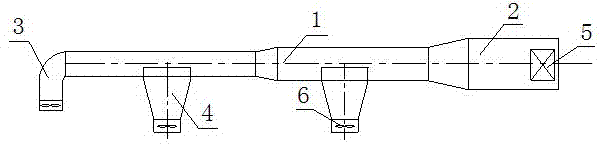
附图1是本实用新型结构示意图,其中1是风力管道,2是大径端,3是弯管端,4是风口段,5是滤尘器,6是抽风机。
Accompanying
具体实施方式 Detailed ways
下面结合附图,对本实用新型的具体实施方式进行说明。本实用新型公开了一种新型厂房回风系统,该系统包括风力管道1、滤尘器5和抽风机6。风力管道1包括大径端2、弯管端3和与若干个与风力管道1连通的风口段4,弯管端3通向室外,风口段4通向室内。在大径端2位置处装有滤尘器5,在弯管端3和风口段4设有抽风机6。
Below in conjunction with accompanying drawing, the specific embodiment of the utility model is described. The utility model discloses a novel factory building return air system, which comprises a
使用时,经过滤尘器5过滤的热风通过风力管道1及其上的风口段4,可排回到车间内,从而实现了热能的再利用。当夏天温度高时,热风通过弯管端3向外排出,从而通过排风位置的选择,实现不同的设计目的。
During use, the hot air filtered by the
当然,上述说明并非对本实用新型的限制,本实用新型也不仅限于上述举例,本技术领域的普通技术人员在本实用新型的实质范围内所做出的变化、改型、添加或替换,也属于本实用新型的保护范围。 Of course, the above descriptions are not limitations of the present utility model, and the present utility model is not limited to the above-mentioned examples. Changes, modifications, additions or replacements made by those of ordinary skill in the art within the essential scope of the present utility model also belong to Protection scope of the present utility model.
Claims (2)
Priority Applications (1)
| Application Number | Priority Date | Filing Date | Title |
|---|---|---|---|
| CN 201220663823 CN202915506U (en) | 2012-12-06 | 2012-12-06 | Novel air returning system for plant |
Applications Claiming Priority (1)
| Application Number | Priority Date | Filing Date | Title |
|---|---|---|---|
| CN 201220663823 CN202915506U (en) | 2012-12-06 | 2012-12-06 | Novel air returning system for plant |
Publications (1)
| Publication Number | Publication Date |
|---|---|
| CN202915506U true CN202915506U (en) | 2013-05-01 |
Family
ID=48163816
Family Applications (1)
| Application Number | Title | Priority Date | Filing Date |
|---|---|---|---|
| CN 201220663823 Expired - Fee Related CN202915506U (en) | 2012-12-06 | 2012-12-06 | Novel air returning system for plant |
Country Status (1)
| Country | Link |
|---|---|
| CN (1) | CN202915506U (en) |
-
2012
- 2012-12-06 CN CN 201220663823 patent/CN202915506U/en not_active Expired - Fee Related
Similar Documents
| Publication | Publication Date | Title |
|---|---|---|
| CN202629166U (en) | Quick exhaust valve | |
| CN204648469U (en) | The modified form air-conditioning system of heat-preservation cotton job shop | |
| CN203571968U (en) | Air conditioner purifying system | |
| CN208858616U (en) | House cooling system | |
| CN202630102U (en) | Intercooling tower hot-air recycling system in thermal power plant | |
| CN202973576U (en) | Simple solar heat collection device | |
| CN202470117U (en) | Dual-purpose household coal furnace for heating and humidification | |
| CN204663990U (en) | A kind of air compressor hot blast treatment device | |
| CN204787279U (en) | Small -size hot -blast furnace air outlet | |
| CN202597149U (en) | Cooling fan | |
| CN205138264U (en) | Novel pressure wind air heat exchanger device | |
| CN202769844U (en) | Ecological air-conditioning fan | |
| CN202885417U (en) | Refrigerator with thermal insulation box | |
| CN206338833U (en) | Kitchen fume ventilating system | |
| CN204213173U (en) | Air-floating main shaft New Damping plug | |
| CN203100480U (en) | Comprehensive utilization heat exchanger | |
| CN203051234U (en) | Heat exhaust device for pressure fan | |
| CN202188520U (en) | Flue gas dust removal system for hot air furnace | |
| CN203923250U (en) | Novel air-curtain type converter secondary flue gas capturing device | |
| CN203099881U (en) | Furnace box temperature increasing device for timber fiber boiler room | |
| CN204051350U (en) | A circulating air environmental protection dust removal device | |
| CN202059269U (en) | Cooling apparatus for blower fan of plastic sheet material production line | |
| CN201994781U (en) | Main motor forced cooling device of straightening machine | |
| CN203116074U (en) | Inlet air channel structure of air preheater of thermal power station | |
| CN202747453U (en) | Smoke exhaust ventilator |
Legal Events
| Date | Code | Title | Description |
|---|---|---|---|
| C14 | Grant of patent or utility model | ||
| GR01 | Patent grant | ||
| CF01 | Termination of patent right due to non-payment of annual fee | ||
| CF01 | Termination of patent right due to non-payment of annual fee |
Granted publication date: 20130501 Termination date: 20161206 |