CN202901951U - Isolating LED lamp tube - Google Patents
Isolating LED lamp tube Download PDFInfo
- Publication number
- CN202901951U CN202901951U CN 201220581565 CN201220581565U CN202901951U CN 202901951 U CN202901951 U CN 202901951U CN 201220581565 CN201220581565 CN 201220581565 CN 201220581565 U CN201220581565 U CN 201220581565U CN 202901951 U CN202901951 U CN 202901951U
- Authority
- CN
- China
- Prior art keywords
- fluorescent tube
- lampshade
- type led
- isolation type
- led fluorescent
- Prior art date
- Legal status (The legal status is an assumption and is not a legal conclusion. Google has not performed a legal analysis and makes no representation as to the accuracy of the status listed.)
- Expired - Lifetime
Links
- 229910052751 metal Inorganic materials 0.000 claims abstract description 10
- 239000002184 metal Substances 0.000 claims abstract description 10
- 238000002955 isolation Methods 0.000 claims description 16
- 239000000463 material Substances 0.000 claims description 9
- 239000011248 coating agent Substances 0.000 claims description 7
- 238000000576 coating method Methods 0.000 claims description 7
- 239000011521 glass Substances 0.000 claims description 4
- 239000004568 cement Substances 0.000 claims description 3
- 230000000694 effects Effects 0.000 description 3
- 238000009413 insulation Methods 0.000 description 3
- 229910052582 BN Inorganic materials 0.000 description 2
- PZNSFCLAULLKQX-UHFFFAOYSA-N Boron nitride Chemical compound N#B PZNSFCLAULLKQX-UHFFFAOYSA-N 0.000 description 2
- GWEVSGVZZGPLCZ-UHFFFAOYSA-N Titan oxide Chemical compound O=[Ti]=O GWEVSGVZZGPLCZ-UHFFFAOYSA-N 0.000 description 2
- 239000000853 adhesive Substances 0.000 description 2
- 230000001070 adhesive effect Effects 0.000 description 2
- 238000005516 engineering process Methods 0.000 description 2
- 239000003292 glue Substances 0.000 description 2
- 238000004519 manufacturing process Methods 0.000 description 2
- 238000000034 method Methods 0.000 description 2
- 150000004767 nitrides Chemical class 0.000 description 2
- 239000011505 plaster Substances 0.000 description 2
- OGIDPMRJRNCKJF-UHFFFAOYSA-N titanium oxide Inorganic materials [Ti]=O OGIDPMRJRNCKJF-UHFFFAOYSA-N 0.000 description 2
- 230000009286 beneficial effect Effects 0.000 description 1
- 208000002173 dizziness Diseases 0.000 description 1
- 238000005401 electroluminescence Methods 0.000 description 1
- 229910052736 halogen Inorganic materials 0.000 description 1
- 125000005843 halogen group Chemical group 0.000 description 1
- 238000005286 illumination Methods 0.000 description 1
- 238000009434 installation Methods 0.000 description 1
- 230000004048 modification Effects 0.000 description 1
- 238000012986 modification Methods 0.000 description 1
- 239000004065 semiconductor Substances 0.000 description 1
- 230000000007 visual effect Effects 0.000 description 1
Images


Landscapes
- Non-Portable Lighting Devices Or Systems Thereof (AREA)
- Arrangement Of Elements, Cooling, Sealing, Or The Like Of Lighting Devices (AREA)
Abstract
The utility model discloses an isolating LED lamp tube which comprises a lamp shade, a lamp strip and an LED light source. The isolating LED lamp tube is characterized in that the lamp shade is in a closed tubular structure, the inner wall of the lamp shade is provided with a clamping part, the lamp strip is directly fitted to the clamping part on the inner wall of the lamp shade and fixed within the lamp shade, and the LED light source is installed on the lamp strip. The isolating LED lamp tube needs no metal radiator in a traditional LED lamp tube and has the advantages of simple structure, high safety and the like.
Description
Technical field
The utility model belongs to the led lighting field, and it is specifically related to a kind of isolation type LED fluorescent tube.
Background technology
Light emitting diode (English is Light Emitting Diode, is called for short LED) is a kind of light emitting semiconductor device that utilizes semi-conductive P-N junction electroluminescence principle to make.At lighting field, the LED electricity-saving lamp replaces the position of Halogen lamp LED and fluorescent lamp just gradually.
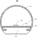
Fig. 1 has shown a kind of traditional LED fluorescent tube design, and its structure mainly comprises: lampshade 11, LED core grain 13, lamp bar 14, insulating heat-conductive glue 15, metal heat sink 16.Described lampshade 11 opening parts are provided with the Access Division of fixing metal radiator 16, and LED core grain is installed on the lamp bar 14, the lamp bar with join in metal heat sink 16.In this LED fluorescent tube 10, have following problem: (1), then must arrange insulation and lead adhesive plaster because there is the electric leakage problem in it because metal heat sink is installed between lamp bar and radiator; (2) led light source is excessively near apart from the fluorescent tube center, to such an extent as to see easily the spot light of LED, is difficult to form area source, and this some people on Human Engineering can cause visual dizzy; (3) if replace existing fluorescent tube, the necessary lamp bracket circuit structure of revising; (4) spare part that uses is too much, causes the LED illumination cost to be difficult to descend.
Summary of the invention
For solving aforementioned prior art problem, the utility model provides a kind of isolation type LED fluorescent tube, and it is fixed in LED lamp bar in the tubulose lampshade of a closure, forms a kind of LED fluorescent tube of isolation type, has use safety, and cost hangs down inferior advantage.
The technical scheme that the utility model addresses the above problem is: isolation type LED fluorescent tube, comprise lampshade, lamp bar and led light source, and it is characterized in that: described lampshade is closed tubular structure, and inwall is provided with the Access Division; Described lamp bar directly cooperates with the Access Division of described lampshade inwall, and it is inner to be fixed in described lampshade; Described led light source is installed on the described lamp bar.
More specifically, aforementioned fluorescent tube is not installed metal heat sink, and shedding of heat is on the lampshade by lampshade or backward luminous source lamp bar, outwards to dispel the heat with thermal-radiating form.
Preferably, described lampshade is integrated the tubular structure of type.
Preferably, described lampshade is glass lamp or plastic cement fluorescent tube.
Preferably, described lamp bar is installed on away from exiting surface one side lamp cover inwall.
In embodiment more of the present utility model, the Access Division of described lampshade inwall is parallel strip projected parts structure, is positioned at the Lower Half of lampshade, by two projections and the described lamp bar of lampshade inwall clamping corresponding to root.
In embodiment more of the present utility model, the Access Division of described lampshade inwall is notch, is positioned at the Lower Half of lampshade pipe.
In embodiment more of the present utility model, described lampshade is that described wedging position is in the root of arc surface by a plane and the closed type body that arc surface consists of.
In embodiment more of the present utility model, can be in lamp bar bottom or fluorescent tube dorsad the lamp source region be provided with the thermal-radiating material coating, improve further heat sinking function.
The utility model comprises following beneficial effect at least: (1) is compared with traditional LED spot design, and its required component reduces a lot, can effectively save the fluorescent tube cost; (2) LED lamp bar is fixed in the tubulose lampshade of a closure, need not to use the insulating heat-conductive adhesive plaster, can avoid the electric leakage problem; (3) led light source is far away apart from the more traditional LED fluorescent tube of lampshade, can increase LED at the inner light mixing effect of fluorescent tube, need not use the fluorescent tube cover of high light loss, therefore can avoid traditional LED fluorescent tube mixed light problem, further, can significantly reduce the generation of multiple image phenomenon; (4) LED lamp tube structure disclosed in the utility model can be integrated in fluorescent tube striation bottom with transformer in conjunction with IC chip manufacturing low (height) pressure transformer, can make whole Design of Luminaires significantly dwindle usage space, and need not change the lamp circuit design.
Other features and advantages of the utility model will be set forth in the following description, and, partly from specification, become apparent, perhaps understand by implementing the present invention.Purpose of the present invention and other advantage can realize and obtain by specifically noted structure in specification, claims and accompanying drawing.
Description of drawings
Accompanying drawing is used to provide a further understanding of the present invention, and consists of the part of specification, is used for together with embodiments of the present invention explaining the present invention, is not construed as limiting the invention.In addition, the accompanying drawing data are to describe summary, are not to draw in proportion.
Fig. 1 is a kind of cutaway view of traditional LED fluorescent tube.
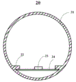
Fig. 2 is the cutaway view of the first embodiment.
Fig. 3 is the cutaway view of the second embodiment.
Fig. 4 is the cutaway view of the 3rd embodiment.
Fig. 5 is the cutaway view of the 4th embodiment.
Fig. 6 is the cutaway view of the 5th embodiment.
Each label represents among the figure:
10,20,30,40,50,40:LED fluorescent tube; 11,21,31,41,51,61: lampshade; 12,22,32,42,52,62: the Access Division; 13,23,33,43,53,63:LED core grain; 14,24,34,44,54,64: the lamp bar; 15 insulating heat-conductive glue; 16: metal heat sink; 55,65: the thermal-radiating material coating.
The specific embodiment
Describe embodiments of the present invention in detail below with reference to drawings and Examples, how the application technology means solve technical problem to the present invention whereby, and the implementation procedure of reaching technique effect can fully understand and implements according to this.Need to prove that only otherwise consist of conflict, each embodiment among the present invention and each feature among each embodiment can mutually combine, formed technical scheme is all within protection scope of the present invention.
Below each embodiment a kind of LED fluorescent tube is disclosed, the tubular structure of its lampshade closed type is generally one-body moldedly, can be glass lamp or plastic cement fluorescent tube, second is provided with the Access Division in pipe, the lamp bar directly is connected to this Access Division.This lamp tube structure need not to install the metal heat sink in traditional LED lighting tube structure, and simple structure is safe.Below by specific embodiment enforcement of the present utility model is described further.
[embodiment 1]
Fig. 2 has shown the profile of embodiment 1 disclosed LED fluorescent tube 20.In the present embodiment, LED fluorescent tube 20 comprises lampshade 21, Access Division 22, LED core grain 23 and lamp bar 24.Wherein, lampshade 21 is the glass cylinder body, lamp bar 24 can be the PCB circuit board, LED core grain is installed on the lamp bar, Access Division 22 is the strip projected parts of pair of parallel, be positioned at the Lower Half of lampshade, and the distance of two protruding roots is slightly larger than the width of described lamp bar, cooperates clamping lamp bar 24 by two projections and lampshade inwall corresponding to root.In this LED lamp tube structure, by the width design Access Division 22 of lamp bar 24, as long as it is at the strip projected parts of lampshade 21 inwalls designs pair of parallel, simple structure, and led light source is away from the lampshade on the exiting surface, and light mixing effect is better; Remove metal heat sink, reduced leaky; Can transformer be integrated in fluorescent tube striation bottom in conjunction with IC chip manufacturing low (height) pressure transformer, can make whole Design of Luminaires significantly dwindle usage space, and need not change the lamp circuit design.
[embodiment 2]
Fig. 3 has shown the profile of embodiment 2 disclosed LED fluorescent tubes 30.The difference of present embodiment and embodiment 1 is 32 difference in the Access Division, and in the present embodiment, Access Division 32 is notch, and this structure is fixed light bar 34 better.
[embodiment 3]
Fig. 4 has shown the profile of embodiment 3 disclosed LED fluorescent tubes 40.The difference of present embodiment and embodiment 1 is different in lampshade 41 shapes.In the present embodiment, lampshade 41 is that Access Division 42 is positioned at two roots of arc surface 41b, is the strip projected parts of pair of parallel by a plane 41a and the closed type body that arc surface 41b consists of, and cooperates the plane tube wall fixed light bar 44 of bottom.In the present embodiment, because the bottom of lampshade is a plane, thereby so that the bottom of whole LED fluorescent tube is the plane, the installation that convenient follow-up use is used.
[embodiment 4]
Fig. 5 has shown the profile of embodiment 4 disclosed LED fluorescent tubes 50.The difference of present embodiment and embodiment 3 is to be provided with thermal-radiating material coating 55 in fluorescent tube 50 bottom surfaces, and its material can be insulation oxide or nitride, such as titanium oxide, boron nitride etc.Set up the thermal-radiating material coating in the fluorescent tube bottom surface, improve further the fluorescent tube heat sinking function.
[embodiment 5]
Fig. 5 has shown the profile of embodiment 5 disclosed LED fluorescent tubes 60.The difference of present embodiment and embodiment 2 is to be provided with thermal-radiating material coating 65 in lamp bar 64 bottom surfaces, and its material can be insulation oxide or nitride, such as titanium oxide, boron nitride etc.Set up the thermal-radiating material coating in the fluorescent tube bottom surface, improve further the fluorescent tube heat sinking function.
The above is the utility model preferred embodiment, is not to limit the utility model, and all other do not break away from the equivalence of finishing under the spirit disclosed in the utility model and change or modification, all should be included in claims.
Claims (11)
1. isolation type LED fluorescent tube comprises lampshade, lamp bar and led light source, it is characterized in that:
Described lampshade is closed tubular structure, and inwall is provided with the Access Division;
Described lamp bar directly cooperates with the Access Division of described lampshade inwall, and it is inner to be fixed in described lampshade;
Described led light source is installed on the described lamp bar.
2. isolation type LED fluorescent tube according to claim 1 is characterized in that: the tubular structure that described lampshade is formed in one.
3. isolation type LED fluorescent tube according to claim 1, it is characterized in that: described lampshade is glass lamp or plastic cement fluorescent tube.
4. isolation type LED fluorescent tube according to claim 1, it is characterized in that: the Access Division of described lampshade inwall is parallel strip projected parts structure, is positioned at the Lower Half of lampshade, by two projections and the described lamp bar of lampshade inwall clamping corresponding to root.
5. isolation type LED fluorescent tube according to claim 1, it is characterized in that: the Access Division of described lampshade inwall is notch, is positioned at the Lower Half of lampshade pipe.
6. isolation type LED fluorescent tube according to claim 1 is characterized in that: described lampshade is for by a plane and the closed type body that arc surface consists of.
7. isolation type LED fluorescent tube according to claim 6, it is characterized in that: described wedging position is in the root of arc surface.
8. isolation type LED fluorescent tube according to claim 1, it is characterized in that: described lamp bar is installed on away from exiting surface one side lamp cover inwall.
9. isolation type LED fluorescent tube according to claim 1, it is characterized in that: described fluorescent tube is not installed metal heat sink.
10. isolation type LED fluorescent tube according to claim 9, it is characterized in that: described fluorescent tube outwards dispels the heat by lampshade with thermal-radiating form.
11. isolation type LED fluorescent tube according to claim 10 is characterized in that: described lamp bar bottom or fluorescent tube dorsad lamp source region are provided with the thermal-radiating material coating.
Priority Applications (1)
| Application Number | Priority Date | Filing Date | Title |
|---|---|---|---|
| CN 201220581565 CN202901951U (en) | 2012-11-07 | 2012-11-07 | Isolating LED lamp tube |
Applications Claiming Priority (1)
| Application Number | Priority Date | Filing Date | Title |
|---|---|---|---|
| CN 201220581565 CN202901951U (en) | 2012-11-07 | 2012-11-07 | Isolating LED lamp tube |
Publications (1)
| Publication Number | Publication Date |
|---|---|
| CN202901951U true CN202901951U (en) | 2013-04-24 |
Family
ID=48122617
Family Applications (1)
| Application Number | Title | Priority Date | Filing Date |
|---|---|---|---|
| CN 201220581565 Expired - Lifetime CN202901951U (en) | 2012-11-07 | 2012-11-07 | Isolating LED lamp tube |
Country Status (1)
| Country | Link |
|---|---|
| CN (1) | CN202901951U (en) |
Cited By (4)
| Publication number | Priority date | Publication date | Assignee | Title |
|---|---|---|---|---|
| CN103574372A (en) * | 2013-11-19 | 2014-02-12 | 王培清 | Tubular LED lamp structure |
| CN103604057A (en) * | 2013-11-25 | 2014-02-26 | 湖州市妙西镇资产经营有限公司 | LED (light emitting diode) lamp structure |
| CN103672524A (en) * | 2013-12-23 | 2014-03-26 | 南京中电熊猫照明有限公司 | LED fluorescent lamp and manufacturing method thereof |
| CN104515079A (en) * | 2013-09-29 | 2015-04-15 | 中山市领航光电科技有限公司 | Novel LED fluorescent tube structure |
-
2012
- 2012-11-07 CN CN 201220581565 patent/CN202901951U/en not_active Expired - Lifetime
Cited By (5)
| Publication number | Priority date | Publication date | Assignee | Title |
|---|---|---|---|---|
| CN104515079A (en) * | 2013-09-29 | 2015-04-15 | 中山市领航光电科技有限公司 | Novel LED fluorescent tube structure |
| CN103574372A (en) * | 2013-11-19 | 2014-02-12 | 王培清 | Tubular LED lamp structure |
| CN103604057A (en) * | 2013-11-25 | 2014-02-26 | 湖州市妙西镇资产经营有限公司 | LED (light emitting diode) lamp structure |
| CN103672524A (en) * | 2013-12-23 | 2014-03-26 | 南京中电熊猫照明有限公司 | LED fluorescent lamp and manufacturing method thereof |
| CN103672524B (en) * | 2013-12-23 | 2016-06-29 | 南京中电熊猫照明有限公司 | A kind of LED daylight lamp and preparation method thereof |
Similar Documents
| Publication | Publication Date | Title |
|---|---|---|
| CN202901952U (en) | LED tube | |
| CN203322802U (en) | High-light efficiency energy-saving LED (light-emitting diode) tube | |
| CN204026589U (en) | A kind of LED cartridge type radiator | |
| CN203010320U (en) | Integration lamp tube | |
| CN204459884U (en) | A kind of LED corn lamp | |
| CN201803185U (en) | LED bulb | |
| CN103925495B (en) | Coating in a kind of LED straight lamp and this LED straight lamp | |
| CN205299127U (en) | LED energy -saving lamp | |
| CN204477983U (en) | A kind of Lamp cup and the integrated assembly of lamp holder | |
| CN203413425U (en) | LED (Light Emitting Diode) lamp | |
| CN205048181U (en) | LED drive power supply electricity -saving lamp | |
| CN204328553U (en) | A kind of LED daylight lamp | |
| CN203273467U (en) | Concatenation type strip-shaped LED (light emitting diode) lamp | |
| CN203868994U (en) | Integrated LED fluorescent lamp tube | |
| CN203052344U (en) | Light-emitting diode (LED) lamp | |
| CN205480463U (en) | LED (light -emitting diode) fluorescent lamp | |
| CN204420888U (en) | A kind of LED shell | |
| CN102141236A (en) | High-power LED (light emitting diode) light fitting radiating device | |
| CN203836659U (en) | Energy-saving LED (Light Emitting Diode) bracket lamp | |
| CN205137221U (en) | Novel mirror front lamp | |
| CN204164749U (en) | Can the LED light source of manual adjustments colour temperature | |
| CN203298212U (en) | LED lamp support | |
| CN203718431U (en) | Thermal insulation LED (light emitting diode) lamp | |
| CN204201827U (en) | Easy-to-dismount LED lamp | |
| CN203099461U (en) | Waterproof type light-emitting diode (LED) energy-saving lamp |
Legal Events
| Date | Code | Title | Description |
|---|---|---|---|
| C14 | Grant of patent or utility model | ||
| GR01 | Patent grant | ||
| CX01 | Expiry of patent term | ||
| CX01 | Expiry of patent term |
Granted publication date: 20130424 |