CN202895537U - Engineering plastic retainer injection mould core for cylindrical roller bearing - Google Patents
Engineering plastic retainer injection mould core for cylindrical roller bearing Download PDFInfo
- Publication number
- CN202895537U CN202895537U CN 201220587325 CN201220587325U CN202895537U CN 202895537 U CN202895537 U CN 202895537U CN 201220587325 CN201220587325 CN 201220587325 CN 201220587325 U CN201220587325 U CN 201220587325U CN 202895537 U CN202895537 U CN 202895537U
- Authority
- CN
- China
- Prior art keywords
- mould core
- movable model
- fixed mold
- movable
- core
- Prior art date
- Legal status (The legal status is an assumption and is not a legal conclusion. Google has not performed a legal analysis and makes no representation as to the accuracy of the status listed.)
- Expired - Fee Related
Links
- 238000002347 injection Methods 0.000 title claims abstract description 14
- 239000007924 injection Substances 0.000 title claims abstract description 14
- 229920006351 engineering plastic Polymers 0.000 title claims abstract description 10
- 229920003023 plastic Polymers 0.000 abstract description 3
- 239000004033 plastic Substances 0.000 abstract description 3
- 238000010586 diagram Methods 0.000 description 21
- 239000000463 material Substances 0.000 description 2
- 230000002950 deficient Effects 0.000 description 1
- 238000000605 extraction Methods 0.000 description 1
- 238000012856 packing Methods 0.000 description 1
- 238000013022 venting Methods 0.000 description 1
Images






Landscapes
- Moulds For Moulding Plastics Or The Like (AREA)
Abstract
The utility model relates to a retainer injection mould core, particularly relates to an engineering plastic retainer injection mould core for a cylindrical roller bearing and belongs to the field of a plastic injection mould. The engineering plastic retainer injection mould core is formed by a movable mould core and a fixed mould core; the movable mould core comprises a movable mould core base, a movable mould core plate and a movable mould core body; the movable mould core base is connected with the movable mould core plate; the movable mould core plate is connected with the movable mould core body, namely the movable mould core plate is located between the movable mould core base and the movable mould core body; an air exhausting channel is arranged between the movable mould core base and the movable mould core plate and also between the movable mould core plate and the movable mould core body; the fixed mould core comprises a fixed mould core base and a fixed mould core plate; the fixed mould core base is connected with the fixed mould core plate; and an air exhausting channel is arranged between the fixed mould core base and the fixed mould core plate.
Description
Technical field
The utility model relates to a kind of retainer injection mold core, specifically relates to a kind of cylinder roller bearing engineering plastics cage injection mold core, and it belongs to the plastics injection mould field.
Background technology
At present, on the structural design of cylinder roller bearing with the engineering plastics cage injection mold core, all adopt monoblock type.Although unitary core is simple in structure, handling ease, but can't design gas extraction system on the core, cause the exhaust performance of mould low, obvious weld bond appears in product, and mechanical performance is not enough, just must offer air discharge duct at mold cavity in order to improve mechanical performance, product just unavoidably produces a large amount of overlaps like this, needs after-treatment, increases the costs such as manpower and materials.Simultaneously, because die venting is bad, plastic melt is filled difficulty, and the product packing is not enough, very easily produces the defectives such as size, outward appearance.
Summary of the invention
In view of the problem that prior art exists, the purpose of this utility model is that a kind of Combined cylindrical roller bearing engineering plastics cage injection mold core will be provided.
To achieve these goals, the technical scheme that the utility model adopts is a kind of cylinder roller bearing engineering plastics cage injection mold core, and it is comprised of dynamic mould core and fixed mold; Described dynamic mould core comprises movable model core print seat, movable model central layer and movable model core body, and the movable model core print seat is connected with the movable model central layer, and the movable model central layer is connected with the movable model core body, and namely the movable model central layer is between movable model core print seat and movable model core body; Be provided with the exhaust passage between movable model core print seat and the movable model central layer, be provided with the exhaust passage between movable model central layer and the movable model core body, described fixed mold comprises fixed mold seat and fixed mold plate, and the fixed mold seat is connected with the fixed mold plate; Be provided with the exhaust passage between fixed mold seat and the fixed mold plate.
The utility model has the advantage of: unitary core is changed to the combined type core; Dynamic mould core changes three parts into by an original part and combines, and designs the exhaust passage between each part; Fixed mold changes two parts into by an original part and combines, and designs the exhaust passage between two; It has not only improved the mechanical performance of product, and the outward appearance of simultaneously also beautifying product is avoided because offering air discharge duct at mold cavity, and produced a large amount of overlaps, needs after-treatment, the problem of the costs such as increase manpower and materials.
Description of drawings
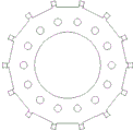
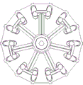
Fig. 1 is the front view schematic diagram of dynamic mould core;
Fig. 2 is the left view schematic diagram of dynamic mould core;
Fig. 3 is the top view schematic diagram of dynamic mould core;
Fig. 4 is the front view schematic diagram of fixed mold;
Fig. 5 is the left view schematic diagram of fixed mold;
Fig. 6 is the top view schematic diagram of fixed mold;
Fig. 7 is the front view schematic diagram of movable model core print seat;
Fig. 8 is the left view schematic diagram of movable model core print seat;
Fig. 9 is the top view schematic diagram of movable model core print seat;
Figure 10 is the front view schematic diagram of movable model central layer;
Figure 11 is the left view schematic diagram of movable model central layer;
Figure 12 is the top view schematic diagram of movable model central layer;
Figure 13 is the front view schematic diagram of movable model core body;
Figure 14 is the left view schematic diagram of movable model core body;
Figure 15 is the top view schematic diagram of movable model core body;
Figure 16 is the front view schematic diagram of fixed mold seat;
Figure 17 is the left view schematic diagram of fixed mold seat;
Figure 18 is the top view schematic diagram of fixed mold seat;
Figure 19 is the front view schematic diagram of fixed mold plate;
Figure 20 is the left view schematic diagram of fixed mold plate;
Figure 21 is the top view schematic diagram of fixed mold plate;
Figure 22 is the side view of mold cores.
The specific embodiment
In order further to understand this cylinder roller bearing engineering plastics cage injection mold core, accompanying drawings is as follows.
It is comprised of dynamic mould core and fixed mold; Described dynamic mould core comprises movable model core print seat, movable model central layer and movable model core body, and the movable model core print seat is connected with the movable model central layer, and the movable model central layer is connected with the movable model core body, and namely the movable model central layer is between movable model core print seat and movable model core body; Be provided with the exhaust passage between movable model core print seat and the movable model central layer, be provided with the exhaust passage between movable model central layer and the movable model core body, described fixed mold comprises fixed mold seat and fixed mold plate, and the fixed mold seat is connected with the fixed mold plate; Be provided with the exhaust passage between fixed mold seat and the fixed mold plate.
Claims (1)
1. cylinder roller bearing engineering plastics cage injection mold core, it is comprised of dynamic mould core and fixed mold; Described dynamic mould core comprises movable model core print seat, movable model central layer and movable model core body, and the movable model core print seat is connected with the movable model central layer, and the movable model central layer is connected with the movable model core body, and namely the movable model central layer is between movable model core print seat and movable model core body; Be provided with the exhaust passage between movable model core print seat and the movable model central layer, be provided with the exhaust passage between movable model central layer and the movable model core body, described fixed mold comprises fixed mold seat and fixed mold plate, and the fixed mold seat is connected with the fixed mold plate; Be provided with the exhaust passage between fixed mold seat and the fixed mold plate.
Priority Applications (1)
| Application Number | Priority Date | Filing Date | Title |
|---|---|---|---|
| CN 201220587325 CN202895537U (en) | 2012-11-09 | 2012-11-09 | Engineering plastic retainer injection mould core for cylindrical roller bearing |
Applications Claiming Priority (1)
| Application Number | Priority Date | Filing Date | Title |
|---|---|---|---|
| CN 201220587325 CN202895537U (en) | 2012-11-09 | 2012-11-09 | Engineering plastic retainer injection mould core for cylindrical roller bearing |
Publications (1)
| Publication Number | Publication Date |
|---|---|
| CN202895537U true CN202895537U (en) | 2013-04-24 |
Family
ID=48116247
Family Applications (1)
| Application Number | Title | Priority Date | Filing Date |
|---|---|---|---|
| CN 201220587325 Expired - Fee Related CN202895537U (en) | 2012-11-09 | 2012-11-09 | Engineering plastic retainer injection mould core for cylindrical roller bearing |
Country Status (1)
| Country | Link |
|---|---|
| CN (1) | CN202895537U (en) |
-
2012
- 2012-11-09 CN CN 201220587325 patent/CN202895537U/en not_active Expired - Fee Related
Similar Documents
| Publication | Publication Date | Title |
|---|---|---|
| CN206475396U (en) | A kind of automotive trim circle mould | |
| CN102785308A (en) | Once-shaped forming die of air chamber rubber diaphragm and forming process | |
| CN204309189U (en) | A kind of rubber rectangular ring mould | |
| CN207240744U (en) | A kind of foam pump check valve flexible glue multiaspect vented mould | |
| CN203371737U (en) | Thermal-insulation hot runner injection mold | |
| CN203527788U (en) | Panel TV set surface frame injection mould | |
| CN202861365U (en) | Die-casting die with exhaust device | |
| CN202241822U (en) | Plastic mould | |
| CN202965079U (en) | Mold for micro-foaming injection molding | |
| CN207206957U (en) | A kind of die floating structure | |
| CN205889784U (en) | Exhaust system of injection mould | |
| CN201720967U (en) | Curing mold with stepped layers | |
| CN202943794U (en) | Core-pulling mechanism of vacuum molding mold of refrigerator inner container | |
| CN203236660U (en) | Mould | |
| CN202986032U (en) | Cooling structure of mould cavity | |
| CN202986031U (en) | Mould cavity cooling structure | |
| CN202781680U (en) | Material feeding flow channel of injection molding mold | |
| CN201848975U (en) | Layered feeding mechanism of polythene (PE) material injection molding mold | |
| CN203004302U (en) | Blister mould of freezing chamber drawer | |
| CN202781673U (en) | Forming mold for seal ring of filter | |
| CN202200850U (en) | Automobile instrument panel formed by gas aided injection molding | |
| CN202207771U (en) | Dual-cavity mode die for cylinder pouring | |
| CN202357380U (en) | Exhausting structure of die | |
| CN202895760U (en) | Double-layer brake piece forming mould capable of opening and closing synchronously | |
| CN202088351U (en) | Straight ejecting and inclined ejecting mechanism of mold |
Legal Events
| Date | Code | Title | Description |
|---|---|---|---|
| C14 | Grant of patent or utility model | ||
| GR01 | Patent grant | ||
| CF01 | Termination of patent right due to non-payment of annual fee |
Granted publication date: 20130424 Termination date: 20151109 |
|
| EXPY | Termination of patent right or utility model |