CN202895422U - Bidirectional brick extruder without reamer - Google Patents
Bidirectional brick extruder without reamer Download PDFInfo
- Publication number
- CN202895422U CN202895422U CN 201220593049 CN201220593049U CN202895422U CN 202895422 U CN202895422 U CN 202895422U CN 201220593049 CN201220593049 CN 201220593049 CN 201220593049 U CN201220593049 U CN 201220593049U CN 202895422 U CN202895422 U CN 202895422U
- Authority
- CN
- China
- Prior art keywords
- brick
- bidirectional
- roller
- shell
- extruder
- Prior art date
- Legal status (The legal status is an assumption and is not a legal conclusion. Google has not performed a legal analysis and makes no representation as to the accuracy of the status listed.)
- Expired - Fee Related
Links
- 239000011449 brick Substances 0.000 title claims abstract description 17
- 230000002457 bidirectional effect Effects 0.000 title abstract 7
- 238000007493 shaping process Methods 0.000 claims description 16
- 238000007599 discharging Methods 0.000 claims description 11
- 238000001125 extrusion Methods 0.000 abstract description 9
- 238000001035 drying Methods 0.000 abstract description 5
- 230000008602 contraction Effects 0.000 abstract 1
- 238000000465 moulding Methods 0.000 description 3
- 238000005516 engineering process Methods 0.000 description 1
- 238000003801 milling Methods 0.000 description 1
- 230000001737 promoting effect Effects 0.000 description 1
Images

Landscapes
- Press-Shaping Or Shaping Using Conveyers (AREA)
Abstract
The utility model relates to brick making equipment, in particular to a bidirectional brick extruder without a reamer. The bidirectional brick extruder solves problems of low forming rate of products, troublesome operation, narrow application range, low extrusion efficiency and the like of an existing spiral brick extruder. The bidirectional brick extruder comprises a shell, a feed inlet and discharge outlets are arranged on the shell, a forming roller and a pressing roller are mounted in the shell, a plurality of annular forming grooves are respectively arranged on an arc-shaped surface of the forming roller and an arc-shaped surface of the pressing roller at intervals, the annular forming grooves on the forming roller are staggered with the annular forming grooves on the pressing roller, and cutters are fixedly arranged in the shell, are positioned at the discharge outlets and extend into the annular forming grooves. The bidirectional brick extruder has the advantages that the bidirectional brick extruder is simple in structure, reasonable in design and high in extrusion efficiency, can be operated easily and conveniently and has certain popularization value, mud strips extruded by the bidirectional brick extruder are uniform, the green brick drying time is short, the internal density of each obtained green brick is uniform, internal stress on each green brick is low, cracks caused by uneven contraction of the green bricks during drying are effectively prevented, the extrusion efficiency is greatly improved, and the productivity is enhanced.
Description
Technical field
The utility model relates to a kind of brick equipment, is specially a kind of without the two-way extruder of reamer.
Background technology
Existing extruder mostly is greatly the spiral extruder, adopts screw rod that pug is extruded from discharging opening, and the spiral squeezing meeting is so that the goods internal stress is larger, internal density is inhomogeneous, when carrying out drying in the later stage, easily shrinks inhomogeneous, produce the crack, reduce the ratio of briquetting of goods, and changing soft mould or during semi-stiff extrusion, to do suitable variation to pitch, structure, joint number and the mud cylinder length of screw reamer, complex operation, narrow application range, in addition, extrusion efficiency is lower, and labour intensity is large.
Summary of the invention
The problems such as the utility model exists in order to solve existing spiral extruder that the product molding rate is low, complex operation, narrow application range and extrusion efficiency are low provide a kind of without the two-way extruder of reamer.
The utility model is to adopt following technical scheme to realize: without the two-way extruder of reamer, comprise shell, cover top portion is provided with charging aperture, the shell both sides are respectively equipped with discharging opening, install in the shell shaping roller that is driven by power set and cooperate with shaping roller roll roller, shaping roller and roll on the curved surfaces of roller all that the interval has some annular forming tank wherein, the interlaced setting of annular forming tank on two rollers, in the shell and be positioned at two discharging opening positions and be fixed with respectively cutting knife, cutting knife stretches in the annular forming tank of corresponding roller.
Described annular forming tank cross section is rectangle, can make to extrude the better moulding of pug.
Adopt structural design of the present utility model, pug is delivered to shaping roller and rolls in the annular forming tank of roller, because shaping roller and roll the interlaced setting of annular forming tank on the curved surfaces of roller, utilize mutual extruding between the two, can obtain quality evenly, the more uniform mud bar of internal density, utilize cutting knife that the mud bar is cut off one by one at the discharging opening place, obtain adobe.
Compared with prior art, the utility model is simple in structure, reasonable in design, easy and simple to handle, and the mud bar of extruding is very even, the brick bat drying time is short, higher extrusion efficiency is arranged, and gained adobe internal density is more even, internal stress is little, prevented that effectively adobe from shrinking inhomogeneous and crack that produce when drying, in addition, because shaping roller and milling roller tube outer surface are equipped with annular forming tank, can greatly improve extrusion efficiency, boost productivity, have certain promotional value.
Description of drawings
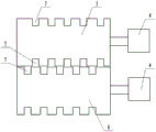
Fig. 1 is structural representation of the present utility model;
Fig. 2 is shaping roller described in the utility model and the structural representation that rolls roller;
Among the figure: the 1-shell; The 2-charging aperture; The 3-discharging opening; The 4-power set; The 5-shaping roller; 6-rolls roller; 7-annular forming tank; The 8-cutting knife.
The specific embodiment
Without the two-way extruder of reamer, such as Fig. 1, shown in 2, comprise shell 1, cover top portion is provided with charging aperture 2, the shell both sides are respectively equipped with discharging opening 3, install in the shell shaping roller 5 that is driven by power set 4 and cooperate with shaping roller roll roller 6, power set can comprise motor and decelerator, shaping roller and roll on the curved surfaces of roller all that the interval has some annular forming tank 7 wherein, the interlaced setting of annular forming tank on two rollers, in the shell, and be positioned at two discharging opening positions and be fixed with respectively cutting knife 8, cutting knife stretches in the annular forming tank of corresponding roller.Annular forming tank 7 cross sections are rectangle, and the degree of depth of annular forming tank and width can require to determine according to green brick forming.
Pug is poured into from charging aperture, enter shaping roller and roll in the annular forming tank of roller, because shaping roller and roll the interlaced setting of annular forming tank on the curved surfaces of roller, utilize mutual extruding between the two to carry out moulding, when pug moves to the discharging opening place, by cutting knife pug is separated from annular forming tank, make pug enter the discharging opening extrusion molding.
Claims (2)
1. one kind without the two-way extruder of reamer, comprise shell (1), cover top portion is provided with charging aperture (2), the shell both sides are respectively equipped with discharging opening (3), it is characterized in that installing in the shell shaping roller (5) that is driven by power set (4) and cooperate with shaping roller roll roller (6), shaping roller and roll on the curved surfaces of roller all that the interval has some annular forming tank (7) wherein, the interlaced setting of annular forming tank on two rollers, in the shell, and be positioned at two discharging opening positions and be fixed with respectively cutting knife (8), cutting knife stretches in the annular forming tank of corresponding roller.
2. according to claim 1 without conic reamer brick extruder, it is characterized in that annular forming tank (7) cross section is rectangle.
Priority Applications (1)
| Application Number | Priority Date | Filing Date | Title |
|---|---|---|---|
| CN 201220593049 CN202895422U (en) | 2012-11-12 | 2012-11-12 | Bidirectional brick extruder without reamer |
Applications Claiming Priority (1)
| Application Number | Priority Date | Filing Date | Title |
|---|---|---|---|
| CN 201220593049 CN202895422U (en) | 2012-11-12 | 2012-11-12 | Bidirectional brick extruder without reamer |
Publications (1)
| Publication Number | Publication Date |
|---|---|
| CN202895422U true CN202895422U (en) | 2013-04-24 |
Family
ID=48116132
Family Applications (1)
| Application Number | Title | Priority Date | Filing Date |
|---|---|---|---|
| CN 201220593049 Expired - Fee Related CN202895422U (en) | 2012-11-12 | 2012-11-12 | Bidirectional brick extruder without reamer |
Country Status (1)
| Country | Link |
|---|---|
| CN (1) | CN202895422U (en) |
-
2012
- 2012-11-12 CN CN 201220593049 patent/CN202895422U/en not_active Expired - Fee Related
Similar Documents
| Publication | Publication Date | Title |
|---|---|---|
| CN203739278U (en) | Bar forming machine | |
| CN204585535U (en) | A kind of ceramic material horizontal multistage vacuum pugging equipment | |
| CN202606547U (en) | Mould for producing large width-to-thickness ratio section bars through continuous extrusion | |
| CN207189904U (en) | Strip antichlor shaped device | |
| CN107824627B (en) | Adjustable support aluminium section hot-extrusion die | |
| CN204934229U (en) | A kind of 7075 aluminium alloy extrusion moulds | |
| CN201998305U (en) | Vacuum hydraulic piston brick making machine | |
| CN115891098A (en) | Screw and extruder for wood-plastic one-step production | |
| CN202895420U (en) | Brick extruder without reamer | |
| CN205767572U (en) | Plastic lawn production line | |
| CN203665680U (en) | Novel die for extrusion ceramic plates | |
| CN201970381U (en) | Circular groove brick extruding machine | |
| CN201760946U (en) | Powerful extruder | |
| CN102729318A (en) | Ceramic roller molding process | |
| CN203622609U (en) | Strong extruder extrusion mechanism | |
| CN204149481U (en) | Tubular die horizontal or vertical install time Ω type coiled material/pipe production line | |
| CN103231438B (en) | Extruder for concrete core slab | |
| CN203076354U (en) | Application structure for extruding large-section material | |
| KR101041744B1 (en) | Aluminum extruded square plate that does not require a shearing process and manufacturing method of fishing reel parts using the same | |
| CN202934686U (en) | Extrusion molding ceramic plate die | |
| CN207402955U (en) | Brickmaking moulded pottery not yet put in a kiln to bake material side integer type device | |
| CN201736319U (en) | Core tool for thin-wall hollow bricks | |
| CN219055462U (en) | Carbon-point extrusion equipment | |
| CN202965155U (en) | Drip irrigation zone extruder | |
| CN218286695U (en) | Rubber tube surface stripe extrusion die |
Legal Events
| Date | Code | Title | Description |
|---|---|---|---|
| C14 | Grant of patent or utility model | ||
| GR01 | Patent grant | ||
| C17 | Cessation of patent right | ||
| CF01 | Termination of patent right due to non-payment of annual fee |
Granted publication date: 20130424 Termination date: 20131112 |