CN202893019U - Connecting structure with filter plate handle positioning block with replaceable thickness - Google Patents
Connecting structure with filter plate handle positioning block with replaceable thickness Download PDFInfo
- Publication number
- CN202893019U CN202893019U CN 201220512120 CN201220512120U CN202893019U CN 202893019 U CN202893019 U CN 202893019U CN 201220512120 CN201220512120 CN 201220512120 CN 201220512120 U CN201220512120 U CN 201220512120U CN 202893019 U CN202893019 U CN 202893019U
- Authority
- CN
- China
- Prior art keywords
- filter plate
- positioning block
- plate handle
- thickness
- handle
- Prior art date
- Legal status (The legal status is an assumption and is not a legal conclusion. Google has not performed a legal analysis and makes no representation as to the accuracy of the status listed.)
- Expired - Fee Related
Links
Images


Landscapes
- Filtering Materials (AREA)
Abstract
本实用新型涉及一种滤板手柄定位块厚度根据需要可以方便更换的一种厚度可更换的滤板手柄定位块连接结构,包括滤板手柄定位块,所述滤板手柄定位块与定位杆旋接装配且位于滤板手柄上。优点:一是滤板定位块与滤板定位杆呈分体旋接结构的设计,实现了滤板定位杆不变,只需更换滤板定位块即能满足不同厚度滤板所需定位块厚度的要求;二是通过改善滤板定位块与滤板定位杆的连接结构,降低压滤机的生产成本。
The utility model relates to a filter plate handle positioning block thickness replaceable filter plate handle positioning block connection structure whose thickness can be conveniently replaced according to needs, including a filter plate handle positioning block, the filter plate handle positioning block is rotated with a positioning rod adapter and located on the filter plate handle. Advantages: First, the design of the filter plate positioning block and the filter plate positioning rod is a separate screw connection structure, which realizes that the filter plate positioning rod remains unchanged, and only needs to replace the filter plate positioning block to meet the thickness of the positioning block required by different thickness filter plates The second is to reduce the production cost of the filter press by improving the connection structure between the filter plate positioning block and the filter plate positioning rod.
Description
技术领域 technical field
本实用新型涉及一种滤板手柄定位块厚度根据需要可以方便更换的一种厚度可更换的滤板手柄定位块连接结构,属滤板手柄制造领域。 The utility model relates to a filter plate handle positioning block connection structure whose thickness can be replaced conveniently according to needs, and belongs to the filter plate handle manufacturing field.
技术背景 technical background
现有的压滤机滤板手柄定位块的结构是在手柄与定位块一起整体成型,这样结构虽然外观比较美观,但由于滤板的厚度随着不同设计条件而产生变化,所以滤板手柄定位块的厚度也要随着滤板的厚度而有所不同,这样就造成了滤板手柄的模具型号比较多,生产成本高,管理难度大,见附图3和4。 The structure of the existing filter plate handle positioning block of the filter press is integrally formed by the handle and the positioning block. Although the appearance of this structure is more beautiful, but because the thickness of the filter plate changes with different design conditions, the filter plate handle positioning The thickness of the block will also vary with the thickness of the filter plate, so that there are many mold models for the filter plate handle, the production cost is high, and the management is difficult, see accompanying drawings 3 and 4.
实用新型内容 Utility model content
设计目的:避免背景技术中的不足之处,设计一种能有效解决了压滤机滤板手柄定位块规格型号多,生产成本高,管理不便等问题的一种厚度可更换的滤板手柄定位块连接结构。 Design purpose: to avoid the deficiencies in the background technology, to design a replaceable filter plate handle positioning that can effectively solve the problems of filter press filter plate handle positioning block specifications and models, high production costs, and inconvenient management. block connection structure.
设计方案:为了实现上述设计目的。滤板手柄定位块的作用是根据不同厚度的滤板,调整定位块的厚度方向尺寸,使相邻两块的手柄定位块之间的间距尽量小,这样,在压滤机的机械自动拉板卸料时,手柄产生微量变形,滤板手柄的定位块与相邻的滤板手柄定位块相碰,使手柄不会产生比较大的变形而产生断裂。 Design scheme: In order to achieve the above design purpose. The function of the filter plate handle positioning block is to adjust the thickness direction size of the positioning block according to the filter plate of different thickness, so that the distance between the two adjacent handle positioning blocks is as small as possible. When unloading, the handle is slightly deformed, and the positioning block of the filter plate handle collides with the adjacent filter plate handle positioning block, so that the handle will not be deformed and broken.
技术方案:一种厚度可更换的滤板手柄定位块连接结构,包括滤板手柄定位块,所述滤板手柄定位块与定位杆旋接装配且位于滤板手柄上。 Technical solution: a filter plate handle positioning block connection structure with replaceable thickness, including the filter plate handle positioning block, the filter plate handle positioning block is screwed and assembled with the positioning rod and located on the filter plate handle.
本实用新型与背景技术相比,一是滤板定位块与滤板定位杆呈分体旋接结构的设计,实现了滤板定位杆不变,只需更换滤板定位块即能满足不同厚度滤板所需定位块厚度的要求;二是通过改善滤板定位块与滤板定位杆的连接结构,降低压滤机的生产成本。 Compared with the background technology, the utility model has the following advantages: one is that the filter plate positioning block and the filter plate positioning rod are designed in a separate screw connection structure, which realizes that the filter plate positioning rod remains unchanged, and only needs to replace the filter plate positioning block to meet different thicknesses The thickness of the positioning block required for the filter plate; the second is to reduce the production cost of the filter press by improving the connection structure between the filter plate positioning block and the filter plate positioning rod.
附图说明 Description of drawings
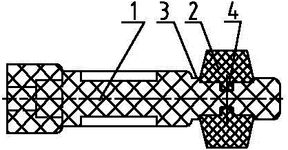
图1是厚度可更换的滤板手柄定位块连接结构的示意图。 Fig. 1 is a schematic diagram of the connection structure of the filter plate handle positioning block with replaceable thickness.
图2是滤板手柄定位块与滤板手柄连接的结构示意图。 Fig. 2 is a structural schematic diagram of the connection between the filter plate handle positioning block and the filter plate handle.
图3是背景技术中滤板手柄定位块的结构示意图。 Fig. 3 is a structural schematic diagram of a filter plate handle positioning block in the background technology.
图4是背景技术中滤板手柄定位块与滤板手柄连接的结构示意图。 Fig. 4 is a structural schematic diagram of the connection between the filter plate handle positioning block and the filter plate handle in the background technology.
具体实施方式 Detailed ways
实施例1:参照图1 图2。一种厚度可更换的滤板手柄定位块连接结构,包括滤板手柄定位块,所述滤板手柄定位块2与定位杆1旋接装配且位于滤板手柄5上,手柄定位块2上端为凸台4。所述定位杆1中用于旋接定位块2定位部呈环形凹槽结构3,环形凹槽中部开有旋接槽且与手柄定位块2上的凸台4匹配。具体实施时,滤板手柄与手柄定位块(图1)采用模具压制成型且通过螺纹结构直接装配,不同滤板厚度需要不同厚度的定位块时,则需要更换不同的定位块,因定位块尺寸较小,制作不同模具,不仅方便,而且成本低,可有效降低压滤机的生产成本。
Embodiment 1: Refer to Figure 1 Figure 2. A filter plate handle positioning block connection structure with replaceable thickness, including a filter plate handle positioning block, the filter plate
需要理解到的是:上述实施例虽然对本实用新型的设计思路作了比较详细的文字描述,但是这些文字描述,只是对本实用新型设计思路的简单文字描述,而不是对本实用新型设计思路的限制,任何不超出本实用新型设计思路的组合、增加或修改,均落入本实用新型的保护范围内。 What needs to be understood is: although the above-mentioned embodiments have done more detailed text descriptions to the design ideas of the present utility model, these text descriptions are only simple text descriptions to the design ideas of the present utility model, rather than limitations to the design ideas of the present utility model. Any combination, addition or modification that does not exceed the design concept of the present utility model falls within the protection scope of the present utility model.
Claims (2)
Priority Applications (1)
| Application Number | Priority Date | Filing Date | Title |
|---|---|---|---|
| CN 201220512120 CN202893019U (en) | 2012-10-08 | 2012-10-08 | Connecting structure with filter plate handle positioning block with replaceable thickness |
Applications Claiming Priority (1)
| Application Number | Priority Date | Filing Date | Title |
|---|---|---|---|
| CN 201220512120 CN202893019U (en) | 2012-10-08 | 2012-10-08 | Connecting structure with filter plate handle positioning block with replaceable thickness |
Publications (1)
| Publication Number | Publication Date |
|---|---|
| CN202893019U true CN202893019U (en) | 2013-04-24 |
Family
ID=48113741
Family Applications (1)
| Application Number | Title | Priority Date | Filing Date |
|---|---|---|---|
| CN 201220512120 Expired - Fee Related CN202893019U (en) | 2012-10-08 | 2012-10-08 | Connecting structure with filter plate handle positioning block with replaceable thickness |
Country Status (1)
| Country | Link |
|---|---|
| CN (1) | CN202893019U (en) |
Cited By (2)
| Publication number | Priority date | Publication date | Assignee | Title |
|---|---|---|---|---|
| CN104906838A (en) * | 2015-05-08 | 2015-09-16 | 浙江金鸟压滤机有限公司 | Detachable filter press filter board handle |
| CN104922953A (en) * | 2015-05-08 | 2015-09-23 | 浙江金鸟压滤机有限公司 | Multifunctional filter plate handle for filter press |
-
2012
- 2012-10-08 CN CN 201220512120 patent/CN202893019U/en not_active Expired - Fee Related
Cited By (2)
| Publication number | Priority date | Publication date | Assignee | Title |
|---|---|---|---|---|
| CN104906838A (en) * | 2015-05-08 | 2015-09-16 | 浙江金鸟压滤机有限公司 | Detachable filter press filter board handle |
| CN104922953A (en) * | 2015-05-08 | 2015-09-23 | 浙江金鸟压滤机有限公司 | Multifunctional filter plate handle for filter press |
Similar Documents
| Publication | Publication Date | Title |
|---|---|---|
| CN203596672U (en) | Stator and rotor cooperation composition suitable for punching sheet arrangement sleeve-punching technology | |
| CN203644553U (en) | Winding mould for oil immersed amorphous alloy transformer | |
| CN204366012U (en) | A kind of mould | |
| CN202270973U (en) | Core bar of powder compacting and moulding 2-cavity mould | |
| CN202668815U (en) | Mould core fast pressing device | |
| CN203061641U (en) | Processing device for one set of door | |
| CN202649688U (en) | An integral animal clock | |
| CN202980581U (en) | Luggage towing box | |
| CN202344414U (en) | Combined die for manufacturing abrasive disc | |
| CN202070741U (en) | Integral material cylinder structure | |
| CN202921895U (en) | Center pull-back device for replacing die-casting mould fast | |
| CN202181017U (en) | Die storage block | |
| CN202388714U (en) | Lower mould for manufacturing leaf filter sheet | |
| CN203072832U (en) | Goniale | |
| CN202111560U (en) | Motor housing | |
| CN203019564U (en) | Five-gallon bucket mold splicing structure | |
| CN201924166U (en) | Rotating shuttle for sewing machine | |
| CN204202507U (en) | Dial gauge gear fixed mount | |
| CN204546840U (en) | The oval mould of a kind of novel precise | |
| CN202934034U (en) | Rib punching die | |
| CN203076420U (en) | Combined die | |
| CN203471927U (en) | Special mold for hydraulic machine for ceramic knives | |
| CN204487921U (en) | A kind of lining ring of stator-core lamination | |
| CN204622397U (en) | A kind of bearing cap mould | |
| CN202323315U (en) | Servo motor synchronous wheel for flat knitting machine |
Legal Events
| Date | Code | Title | Description |
|---|---|---|---|
| C14 | Grant of patent or utility model | ||
| GR01 | Patent grant | ||
| CF01 | Termination of patent right due to non-payment of annual fee |
Granted publication date: 20130424 Termination date: 20161008 |
|
| CF01 | Termination of patent right due to non-payment of annual fee |