CN202879598U - Sheet-tailor-welded cavity truss-type auxiliary carframe with crash safety function - Google Patents

Sheet-tailor-welded cavity truss-type auxiliary carframe with crash safety function Download PDF

Info

Publication number
CN202879598U
CN202879598U CN 201220471502 CN201220471502U CN202879598U CN 202879598 U CN202879598 U CN 202879598U CN 201220471502 CN201220471502 CN 201220471502 CN 201220471502 U CN201220471502 U CN 201220471502U CN 202879598 U CN202879598 U CN 202879598U
Authority
CN
China
Prior art keywords
beam assembly
assembly
truss
cavity
subframe
Prior art date
Legal status (The legal status is an assumption and is not a legal conclusion. Google has not performed a legal analysis and makes no representation as to the accuracy of the status listed.)
Expired - Fee Related
Application number
CN 201220471502
Other languages
Chinese (zh)
Inventor
李玉刚
许小勇
周长波
李国庆
刘成杰
Current Assignee (The listed assignees may be inaccurate. Google has not performed a legal analysis and makes no representation or warranty as to the accuracy of the list.)
SAIC Motor Corp Ltd
Original Assignee
SAIC Motor Corp Ltd
Priority date (The priority date is an assumption and is not a legal conclusion. Google has not performed a legal analysis and makes no representation as to the accuracy of the date listed.)
Filing date
Publication date
Application filed by SAIC Motor Corp Ltd filed Critical SAIC Motor Corp Ltd
Priority to CN 201220471502 priority Critical patent/CN202879598U/en
Application granted granted Critical
Publication of CN202879598U publication Critical patent/CN202879598U/en
Anticipated expiration legal-status Critical
Expired - Fee Related legal-status Critical Current

Links

Images

Landscapes

  • Body Structure For Vehicles (AREA)

Abstract

本实用新型涉及汽车领域,尤其涉及一种汽车副车架。一种薄板拼焊空腔桁架式带碰撞安全功能的副车架,包括右纵梁总成、左纵梁总成、前横梁总成和后横梁总成四部分构成,所述右纵梁总成、左纵梁总成、前横梁总成和后横梁总成固定相连成为一个框体,该框体为空腔桁架结构,前横梁总成和后横梁总成的两端设有车身安装孔,前横梁总成中部设有一对动力总成支架。针对碰撞安全要求,本实用新型具有两类失效模式的结构设计形式,发生碰撞时,动力总成将随被破坏的副车架一起跌落;副车架左右纵梁均呈现两头高中间低的凹形结构即U结构纵梁,且纵梁设计碰撞诱导槽结构,易于实现车辆发生碰撞后,副车架本体发生自动溃缩,最大程度的保障了车内乘员安全。

Figure 201220471502

The utility model relates to the field of automobiles, in particular to an automobile auxiliary frame. A thin plate tailor-welded cavity truss type sub-frame with collision safety function, comprising four parts: right longitudinal beam assembly, left longitudinal beam assembly, front cross beam assembly and rear cross beam assembly, the right longitudinal beam assembly The left longitudinal beam assembly, the front beam assembly and the rear beam assembly are fixedly connected to form a frame body, which is a cavity truss structure, and the two ends of the front beam assembly and the rear beam assembly are provided with body mounting holes , There is a pair of powertrain brackets in the middle of the front beam assembly. In view of the collision safety requirements, the utility model has a structural design form of two types of failure modes. When a collision occurs, the power assembly will fall together with the damaged sub-frame; The U-shaped structure is the U-structure longitudinal beam, and the longitudinal beam is designed with a collision induction groove structure, which is easy to realize that the sub-frame body automatically collapses after the vehicle collides, and ensures the safety of the occupants in the vehicle to the greatest extent.

Figure 201220471502

Description

The subframe of thin plate welding cavity truss-like band crash safety functions
Technical field
The utility model relates to automotive field, relates in particular to a kind of automobile accessory frame.
Background technology
Because subframe carries dynamic assembly, suspension system and steering swivel system, so each system needs subframe that enough bulk strengths and integral rigidity are provided, and for satisfying this demand, during the design subframe, often adopts high tensile steel plate and and complicated structure in the industry.But high strength material steel plate deep drawability is poor, and complicated auxiliary frame structure is unfavorable for making and loss of weight.In addition, recognize gradually in the industry that existing automobile accessory frame can not effectively absorb the ability in the collision process, proposed two class subframe failure modes, to improve member's collision safety.
A kind of inefficacy energy-absorbing modes namely is can separate with vehicle body immediately at the vehicle collision Rear secondary frame for vehicle, and dynamic assembly falls.Be that the 52-11717 Japanese Utility Model is announced a kind of subframe fastener such as the patent No., utilize the bolt connecting bridge fracture of subframe and the vehicle body support of supporting suspension arm, so that subframe separates with vehicle body.
Another kind of inefficacy energy-absorbing modes namely is to produce crumple at the vehicle collision Rear secondary frame for vehicle at fore-and-aft direction.As disclosed among the existing Chinese patent 202046368U, in subframe front end extra soldered one collision energy-absorbing framed structure.These framed structure both sides all connect with 2 U-shaped punching press panel beating button weldings and form, and frame front end is the crossbeam of a long 500mm of surpassing.This structure not only input cost is higher, and so that subframe weight greatly increase.
Summary of the invention
Technical problem to be solved in the utility model provides a kind of subframe of thin plate welding cavity truss-like band crash safety functions, when this subframe bumps, hold-down bolt between subframe and the vehicle body is cut off, dynamic assembly will fall with destroyed subframe, and automatic buckling occurs in this cognition of subframe, has farthest ensured passenger's safety.
The utility model is achieved in that a kind of subframe of thin plate welding cavity truss-like band crash safety functions, comprise that right vertical beam assembly, left longeron assembly, front cross rail assembly and rear cross beam assembly four parts consist of, described right vertical beam assembly, left longeron assembly, front cross rail assembly and rear cross beam assembly are fixedly linked becomes a framework, this framework is the cavity truss structure, the two ends of front cross rail assembly and rear cross beam assembly are provided with the vehicle body mounting hole, be fastenedly connected by hold-down bolt and vehicle body, front cross rail assembly middle part is provided with a pair of dynamic assembly support.
Described right vertical beam assembly and left longeron assembly are arcs of recesses low between the senior middle school of two.
The front end of described right vertical beam assembly and left longeron assembly is provided with induces groove.
The described groove of inducing is Long Circle.
The cavity truss structure of the subframe of the utility model thin plate welding cavity truss-like band crash safety functions has larger integral rigidity and higher resistance to overturning, and is simple in structure, cheap for manufacturing cost; When bumping, the hold-down bolt between subframe and the vehicle body is cut off, and dynamic assembly will fall with destroyed subframe; It is U structure longeron that the subframe left-right longeron all presents concave structure low between the senior middle school of two, and longeron design collision-induced groove structure, and after being easy to realize collision happens, subframe body generation automatic buckling has farthest ensured passenger's safety.
Description of drawings
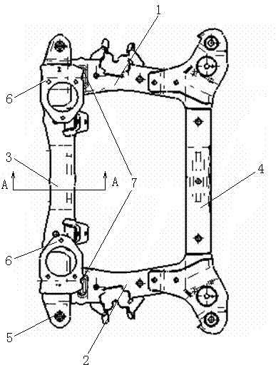
Fig. 1 is the auxiliary frame structure schematic top plan view of the utility model thin plate welding cavity truss-like band crash safety functions;
Fig. 2 is that the utility model structure master looks scheme drawing;
Fig. 3 is the A-A section drawing of Fig. 1.
Among the figure: 1 right vertical beam assembly, 2 left longeron assemblies, 3 front cross rail assemblies, 4 rear cross beam assemblies, 5 vehicle body mounting holes, 6 dynamic assembly supports, 7 are induced groove, 8 vehicle bodies.
The specific embodiment
Below in conjunction with specific embodiment, further set forth the utility model.Should be understood that these embodiment only are used for explanation the utility model and are not used in the scope of the present utility model that limits.Should be understood that in addition those skilled in the art can make various changes or modifications the utility model after the content of having read the utility model statement, these equivalent form of values fall within the application's appended claims limited range equally.
Embodiment 1
Such as Fig. 1, shown in 2, a kind of subframe of thin plate welding cavity truss-like band crash safety functions, comprise right vertical beam assembly 1, left longeron assembly 2, front cross rail assembly 3 and rear cross beam assembly 4 four parts consist of, described right vertical beam assembly 1, left longeron assembly 2, front cross rail assembly 3 and rear cross beam assembly 4 are fixedly linked becomes a framework, this framework is the cavity truss structure, the cavity truss structure as shown in Figure 3, each assembly be thin plate fasten up and down the welding form, the subframe of this configuration state has larger integral rigidity and higher resistance to overturning, simple in structure, cheap for manufacturing cost; The two ends of front cross rail assembly 3 and rear cross beam assembly 4 are provided with vehicle body mounting hole 5, are used for being connected with vehicle body 8, and front cross rail assembly 3 middle parts are provided with a pair of dynamic assembly support 6.
In the utility model, for can be when bumping, two class failure modes occur in the vehicle frame body, and the hold-down bolt between subframe and the vehicle body 8 is cut off, and dynamic assembly will fall with destroyed subframe; The described right vertical beam assembly 1 of automatic buckling and left longeron assembly 2 are arcs of recesses low between the senior middle school of two; And be provided with by the front end at described right vertical beam assembly 1 and left longeron assembly 2 and induce groove 7, improve the crumple effect.In the present embodiment, as preferably, the described groove 7 of inducing is Long Circle.

Claims (4)

1. a thin plate welds the subframe of cavity truss-like band crash safety functions, it is characterized in that: comprise that right vertical beam assembly (1), left longeron assembly (2), front cross rail assembly (3) and rear cross beam assembly (4) four parts consist of, described right vertical beam assembly (1), left longeron assembly (2), front cross rail assembly (3) and rear cross beam assembly (4) are fixedly linked becomes a framework, and this framework is the cavity truss structure; The two ends of front cross rail assembly (3) and rear cross beam assembly (4) are provided with vehicle body mounting hole (5), are fastenedly connected by hold-down bolt and vehicle body, and front cross rail assembly (3) middle part is provided with a pair of dynamic assembly support (6).
2. thin plate as claimed in claim 1 welds the subframe of cavity truss-like band crash safety functions, it is characterized in that: described right vertical beam assembly (1) and left longeron assembly (2) are low arcs of recesses between the senior middle school of two.
3. thin plate as claimed in claim 1 or 2 welds the subframe of cavity truss-like band crash safety functions, and it is characterized in that: the front end of described right vertical beam assembly (1) and left longeron assembly (2) is provided with induces groove (7).
4. thin plate as claimed in claim 3 welds the subframe of cavity truss-like band crash safety functions, and it is characterized in that: the described groove (7) of inducing is Long Circle.
CN 201220471502 2012-09-17 2012-09-17 Sheet-tailor-welded cavity truss-type auxiliary carframe with crash safety function Expired - Fee Related CN202879598U (en)

Priority Applications (1)

Application Number Priority Date Filing Date Title
CN 201220471502 CN202879598U (en) 2012-09-17 2012-09-17 Sheet-tailor-welded cavity truss-type auxiliary carframe with crash safety function

Applications Claiming Priority (1)

Application Number Priority Date Filing Date Title
CN 201220471502 CN202879598U (en) 2012-09-17 2012-09-17 Sheet-tailor-welded cavity truss-type auxiliary carframe with crash safety function

Publications (1)

Publication Number Publication Date
CN202879598U true CN202879598U (en) 2013-04-17

Family

ID=48071054

Family Applications (1)

Application Number Title Priority Date Filing Date
CN 201220471502 Expired - Fee Related CN202879598U (en) 2012-09-17 2012-09-17 Sheet-tailor-welded cavity truss-type auxiliary carframe with crash safety function

Country Status (1)

Country Link
CN (1) CN202879598U (en)

Cited By (6)

* Cited by examiner, † Cited by third party
Publication number Priority date Publication date Assignee Title
CN103287496A (en) * 2013-06-27 2013-09-11 长城汽车股份有限公司 Auxiliary frame used for vehicles and vehicle with same
CN109823398A (en) * 2019-01-29 2019-05-31 重庆长安汽车股份有限公司 A kind of automobile rear sub-frame assembly
CN111391921A (en) * 2020-03-25 2020-07-10 上汽通用汽车有限公司 Automobile auxiliary frame, vehicle and installation method of automobile auxiliary frame
CN111746650A (en) * 2019-03-26 2020-10-09 浙江吉智新能源汽车科技有限公司 Front auxiliary frame of automobile and automobile
CN115009378A (en) * 2022-06-23 2022-09-06 中国第一汽车股份有限公司 a floor rear longitudinal beam
CN119160283A (en) * 2024-10-08 2024-12-20 奇瑞汽车股份有限公司 Front subframe structure and automobile

Cited By (8)

* Cited by examiner, † Cited by third party
Publication number Priority date Publication date Assignee Title
CN103287496A (en) * 2013-06-27 2013-09-11 长城汽车股份有限公司 Auxiliary frame used for vehicles and vehicle with same
CN103287496B (en) * 2013-06-27 2016-05-11 长城汽车股份有限公司 For the subframe of vehicle and there is its vehicle
CN109823398A (en) * 2019-01-29 2019-05-31 重庆长安汽车股份有限公司 A kind of automobile rear sub-frame assembly
CN111746650A (en) * 2019-03-26 2020-10-09 浙江吉智新能源汽车科技有限公司 Front auxiliary frame of automobile and automobile
CN111746650B (en) * 2019-03-26 2022-04-12 浙江吉智新能源汽车科技有限公司 An automobile front subframe and automobile
CN111391921A (en) * 2020-03-25 2020-07-10 上汽通用汽车有限公司 Automobile auxiliary frame, vehicle and installation method of automobile auxiliary frame
CN115009378A (en) * 2022-06-23 2022-09-06 中国第一汽车股份有限公司 a floor rear longitudinal beam
CN119160283A (en) * 2024-10-08 2024-12-20 奇瑞汽车股份有限公司 Front subframe structure and automobile

Similar Documents

Publication Publication Date Title
JP4525802B2 (en) Vehicle skeleton structure
US8714635B2 (en) Front body of vehicle
JP2018039312A (en) Rear body structure of the vehicle
CN103144673B (en) Subframe and there is its automobile
CN101947977A (en) Novel collapsing and energy absorbing auxiliary frame
CN203094189U (en) An energy-absorbing structure of an automobile sub-frame
CN207902549U (en) Vehicle frame
CN205059737U (en) Bracket before full frame of vehicle chassis
CN201737054U (en) Collapsing absorbing energy type auxiliary frame
CN203651909U (en) Unitary construction body with auxiliary frame
CN103419845A (en) Automobile front auxiliary frame installing structure
CN203237188U (en) Anti-collision cross beam structure of vehicle
CN103318265B (en) Rear force transmission structure of automobile
CN201800778U (en) Novel crumpling energy absorbing type subframe
CN204197031U (en) Subframe and vehicle
CN202827023U (en) Supporting structure of automobile front shock absorber
CN207416955U (en) Front longitudinal beam structure of automobile
CN201890135U (en) Automobile-used fuel tank mounting frame
CN201703435U (en) Front longitudinal beam of automobile engine compartment
CN101712305A (en) Vehicle energy absorption box
CN217146150U (en) Front auxiliary frame assembly and vehicle
JP6595283B2 (en) Body structure
CN103253294B (en) steering column assembly connecting structure
CN109823398A (en) A kind of automobile rear sub-frame assembly
CN203402281U (en) Integrated floor beam

Legal Events

Date Code Title Description
C14 Grant of patent or utility model
GR01 Patent grant
CF01 Termination of patent right due to non-payment of annual fee

Granted publication date: 20130417

Termination date: 20200917