CN202861491U - Connecting rod milling locking joint device - Google Patents
Connecting rod milling locking joint device Download PDFInfo
- Publication number
- CN202861491U CN202861491U CN 201220536501 CN201220536501U CN202861491U CN 202861491 U CN202861491 U CN 202861491U CN 201220536501 CN201220536501 CN 201220536501 CN 201220536501 U CN201220536501 U CN 201220536501U CN 202861491 U CN202861491 U CN 202861491U
- Authority
- CN
- China
- Prior art keywords
- connecting rod
- milling cutter
- locking joint
- travelling table
- utility
- Prior art date
- Legal status (The legal status is an assumption and is not a legal conclusion. Google has not performed a legal analysis and makes no representation as to the accuracy of the status listed.)
- Expired - Fee Related
Links
- 238000003801 milling Methods 0.000 title claims abstract description 22
- 238000003754 machining Methods 0.000 abstract description 5
- 238000000034 method Methods 0.000 abstract description 3
- 238000005516 engineering process Methods 0.000 description 2
- 238000005336 cracking Methods 0.000 description 1
- 230000007812 deficiency Effects 0.000 description 1
- 239000012467 final product Substances 0.000 description 1
- 239000000047 product Substances 0.000 description 1
- 230000000630 rising effect Effects 0.000 description 1
- 239000007858 starting material Substances 0.000 description 1
Images

Landscapes
- Milling Processes (AREA)
Abstract
The utility model relates to a connecting rod milling locking joint device, which comprises a fixing rod, a connecting rod, a milling cutter, a moving operating table, a motor, a limiting block, a locking joint and the like. The device is characterized in that the fixing rod is arranged on the moving operating table; the connecting rod is fixed on the moving operating table through the fixing rod; the big end of the connecting rod corresponds to a machining position of the milling cutter; the locking joint is positioned on a combining surface of an inner circle of the big end of the connecting rod; the milling cutter is mounted on the motor; and the limiting block is arranged on the right side of the moving operating table. According to the utility model, the only requirement is to place the big end of the connecting rod on the machining position, i.e. only one-time machining is required to be carried out by the milling cutter, and the process that a connecting rod body and a connecting rod cover are machined respectively is not required. Therefore, the mounting and clamping process is emitted, and the machining error is avoided.
Description
Technical field
[0001] the utility model relates to field of machining, and specifically a kind of connecting rod mills lock catch device.
Background technology
We know, the faying face of cracking connecting rod of rising does not allow to polish, milling in the fore shaft technique in the past, connecting rod need to be taken apart, then respectively con-rod only and connecting rod cap be carried out milling machine operation, this just causes needs twice clamping, affected operating efficiency, and to two parts processing fore shaft, cause scale error large respectively, product quality can not be guaranteed.
Summary of the invention
Technical problem to be solved in the utility model is to overcome above-mentioned the deficiencies in the prior art, and a kind of clamped one time is provided, and the connecting rod that simultaneously con-rod only and connecting rod cap is carried out milling mills lock catch device.
The utility model solves the problems of the technologies described above the technical scheme that adopts: a kind of connecting rod mills lock catch device, be provided with fixed bar, connecting rod, milling cutter, travelling table, motor, limited block, fore shaft, it is characterized in that: travelling table is provided with fixed bar, fixed bar is fixed on connecting rod on the travelling table, the Working position of the corresponding milling cutter of connecting rod tip, fore shaft is positioned on the faying face of connecting rod tip inner circle, and milling cutter is installed on the motor, and the travelling table right side is provided with limited block.
The utility model as long as connecting rod tip is placed in Working position, adopts the milling cutter time processing to get final product owing to adopt said structure, need not con-rod only and connecting rod cap to be processed respectively again, has saved the clamping operation, has avoided mismachining tolerance.
Description of drawings
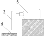
Fig. 1 is front view of the present utility model;
Fig. 2 is right view of the present utility model;
Fig. 3 is connecting rod stereogram of the present utility model.
Be labeled as among the figure: 1. fixed bar, 2. connecting rod, 3. milling cutter, 4. travelling table, 5. motor, 6. limited block, 7. fore shaft.
The specific embodiment
Below in conjunction with accompanying drawing the utility model is described further:
As shown in Figure 1, the utility model relates to a kind of connecting rod and mills lock catch device, by fixed bar 1, connecting rod 2, milling cutter 3, travelling table 4, motor 5, limited block 6, fore shaft 7, it is characterized in that: travelling table 4 is provided with fixed bar 1, fixed bar 1 is fixed on connecting rod 2 on the travelling table 4, the Working position of the corresponding milling cutter 3 of connecting rod 2 large ends, fore shaft 7 is positioned on the faying face of connecting rod 2 large end inner circles, milling cutter 3 is installed on the motor 5, travelling table 4 right sides are provided with limited block 6, limited block 6 is used for walking of control travelling table 4, with the working depth of accurate control fore shaft 7.
When the utility model uses, at first, connecting rod is fixed on the fixed bar, so that the Working position of the corresponding milling cutter of connecting rod tip, then starter motor drives the milling cutter rotation, promotes travelling table to right travel, when travelling table moved to limited block, fore shaft machined.
Claims (1)
1. a connecting rod mills lock catch device, be provided with fixed bar, connecting rod, milling cutter, travelling table, motor, limited block, fore shaft, it is characterized in that: travelling table is provided with fixed bar, fixed bar is fixed on connecting rod on the travelling table, the Working position of the corresponding milling cutter of connecting rod tip, fore shaft is positioned on the faying face of connecting rod tip inner circle, and milling cutter is installed on the motor, and the travelling table right side is provided with limited block.
Priority Applications (1)
| Application Number | Priority Date | Filing Date | Title |
|---|---|---|---|
| CN 201220536501 CN202861491U (en) | 2012-10-19 | 2012-10-19 | Connecting rod milling locking joint device |
Applications Claiming Priority (1)
| Application Number | Priority Date | Filing Date | Title |
|---|---|---|---|
| CN 201220536501 CN202861491U (en) | 2012-10-19 | 2012-10-19 | Connecting rod milling locking joint device |
Publications (1)
| Publication Number | Publication Date |
|---|---|
| CN202861491U true CN202861491U (en) | 2013-04-10 |
Family
ID=48028249
Family Applications (1)
| Application Number | Title | Priority Date | Filing Date |
|---|---|---|---|
| CN 201220536501 Expired - Fee Related CN202861491U (en) | 2012-10-19 | 2012-10-19 | Connecting rod milling locking joint device |
Country Status (1)
| Country | Link |
|---|---|
| CN (1) | CN202861491U (en) |
Cited By (2)
| Publication number | Priority date | Publication date | Assignee | Title |
|---|---|---|---|---|
| CN107755746A (en) * | 2017-10-31 | 2018-03-06 | 芜湖航天汽车连杆有限公司 | Crank pin end pore entirety Boring detent mechanism |
| CN107876821A (en) * | 2017-10-31 | 2018-04-06 | 芜湖航天汽车连杆有限公司 | Crank pin end pore Integral processing device |
-
2012
- 2012-10-19 CN CN 201220536501 patent/CN202861491U/en not_active Expired - Fee Related
Cited By (3)
| Publication number | Priority date | Publication date | Assignee | Title |
|---|---|---|---|---|
| CN107755746A (en) * | 2017-10-31 | 2018-03-06 | 芜湖航天汽车连杆有限公司 | Crank pin end pore entirety Boring detent mechanism |
| CN107876821A (en) * | 2017-10-31 | 2018-04-06 | 芜湖航天汽车连杆有限公司 | Crank pin end pore Integral processing device |
| CN107876821B (en) * | 2017-10-31 | 2020-02-18 | 芜湖航天汽车连杆有限公司 | Integral machining device for big end hole of connecting rod |
Similar Documents
| Publication | Publication Date | Title |
|---|---|---|
| CN202377842U (en) | Special power head for end surface of numerical control boring machine | |
| CN204053483U (en) | Automobile swing arm special boring machine | |
| CN201969879U (en) | Continuous turning device of machine tool | |
| CN201537810U (en) | Automatic machining device for pin holes of hydraulic tappets | |
| CN108672731A (en) | A kind of cylinder cap camshaft hole machining tool and its application method | |
| CN202517063U (en) | Cutter for machining groove on end face of elastic body | |
| CN204108317U (en) | Involute spline eccentric shaft processing unit (plant) | |
| CN101234437A (en) | A milling method and equipment for arc surface milling of fist part of automobile front axle | |
| CN203409268U (en) | Double-tool base lathe | |
| CN203936382U (en) | Medium size bearing lathe | |
| CN104439372B (en) | A kind of digital-control boring-milling machine for processing complex-curved deep chamber | |
| CN103480864B (en) | The Lathe Spindle Box of built-in boring device | |
| CN204135344U (en) | The numerically controlled lathe of processing engine crankshaft connecting rod | |
| CN103418802A (en) | Conveyor roll-shaft end cap machining tool | |
| CN103769659A (en) | Connecting rod milling lock notch apparatus | |
| CN201880972U (en) | Machine tool with support at the end of tool bit | |
| CN205702516U (en) | A kind of vehicle planetary wheel machining composite molding cutter | |
| CN204818709U (en) | Utensil terminal surface processingequipment's combined machining machine | |
| CN203610698U (en) | Mechanical cutting tool | |
| CN202336719U (en) | Machine tool with turning tool rods fixed on both sides | |
| CN203578773U (en) | Lathe | |
| CN203495244U (en) | Plastic part inner circle arc eccentric turning tool | |
| CN102974843A (en) | Spherical processing device | |
| CN202607371U (en) | Turning lathe with automatic axial feeding system | |
| CN202317299U (en) | Numerical control large-scale spiral bevel gear broaching machine beam clamping device |
Legal Events
| Date | Code | Title | Description |
|---|---|---|---|
| C14 | Grant of patent or utility model | ||
| GR01 | Patent grant | ||
| CF01 | Termination of patent right due to non-payment of annual fee |
Granted publication date: 20130410 Termination date: 20141019 |
|
| EXPY | Termination of patent right or utility model |