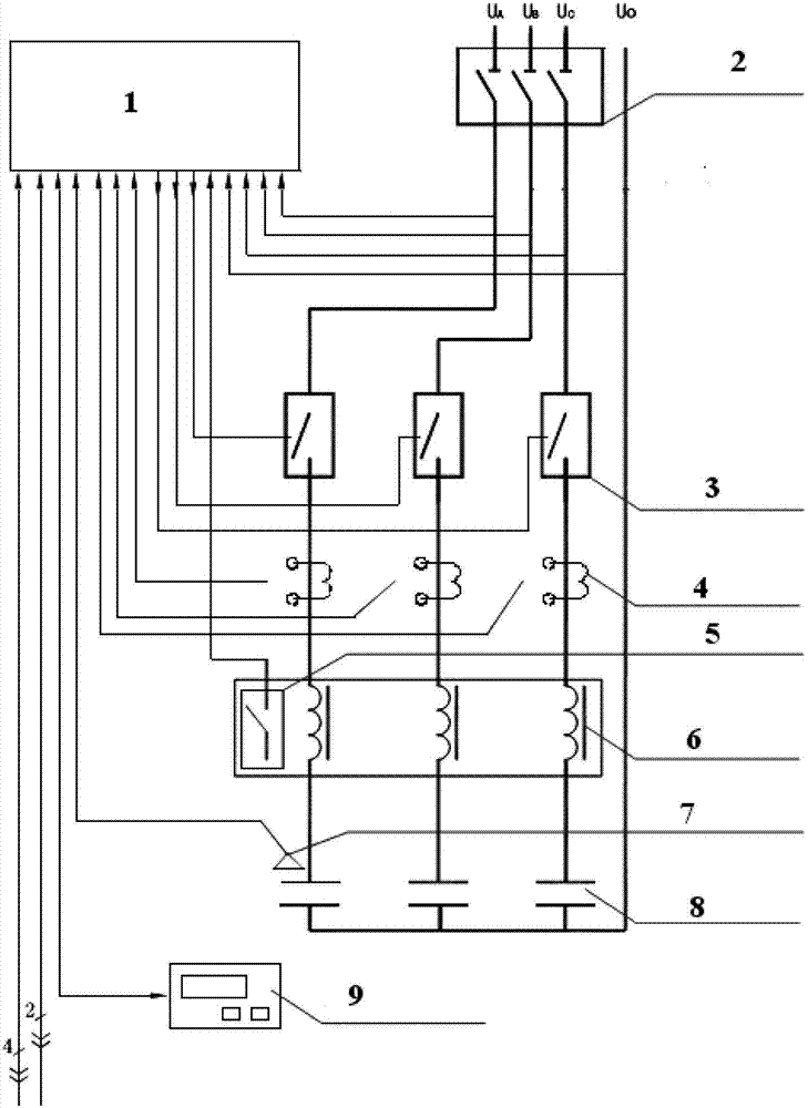
The intelligent low-pressure reactive compensation system
Technical field
The utility model relates to a kind of intelligent low-pressure reactive compensation system, belongs to the technical field of electric automatization.
Background technology
In the modern enterprise, the inductive loads such as motor occupy quite large proportion, in order to guarantee the reliability of motor drive system, when selecting motor, often capacity is bigger than normal, the phenomenon of " low load with strong power " occurs, the load factor of motor is reduced, cause power factor and decrease in efficiency.The peak efficiency of motor generally occurs during full load 75%, and the power factor of motor is then the highest when full load.They also need to absorb a large amount of reactive powers when consuming active power.The appearance of reactive power not only causes generator output to descend, and has reduced equipment for power transmission and distribution efficient, but also has increased network loss, has a strong impact on power supply quality.
Address this problem, major measure is increase-volume at present, namely enlarges transformer and distribution line capacity, thereby improves power supply capacity.But the increase-volume investment is large, and the construction work amount is large, and the cycle is long.Compare, reactive power compensation is very large to the energy-saving and cost-reducing meaning of enterprise.If
Then
S=, this moment, whole switchgear house active power equated substantially that with reactive power it is reactive power that the load of transmission line, transformer has half, moreover the Power consumption and electric current of circuit, transformer square be directly proportional, this numeral is very huge.If power factor is brought up to more than 0.95, reactive power reduces greatly, and energy-saving effect is remarkable.
Most of enterprise is not enough to the understanding of reactive power compensation, only be the examination of transferring electricity price in order to deal with power department power, paid attention to the high-pressure reactive compensation in the transformer station, and the low-pressure reactive compensation of on-site often get the brush-off, even ignore, cause a large amount of wastes of the energy.The Some Enterprises power houses are in order to reduce the maintenance cost of failure rate and equipment, and low-pressure reactive compensation is in exit status, and power factor is on the low side.Some Enterprises is thought power plant for self-supply, and generator can output reactive power, and transmission distance is short again between enterprise and the power plant, reduces line loss and has little significance, so ignored reactive power compensation.In fact, reducing line loss only is one of them index, the manager has ignored the effective output of generator, if reactive power compensation on the spot, generator increases multiple active power in few situation in coal consumption, reduce the electric weight of purchasing from network, analyze from energy-conservation angle with consumption, the profit of enterprise can be more considerable.
Summary of the invention
For the deficiencies in the prior art, the utility model provides a kind of intelligent low-pressure reactive compensation system, and this system's current collection net monitoring and reactive power compensation are in one, reactive loss in not only can compensation network, improve power factor, reduce line loss, thereby improve load capacity and the power supply quality of electrical network; The service datas such as three-phase voltage that simultaneously can also the Real-Time Monitoring electrical network, electric current, power factor can be finished the integrated treatments such as monitoring to whole low-voltage distributing line, analyzing and processing, report output.
The technical solution of the utility model is as follows:
A kind of intelligent low-pressure reactive compensation system comprises intelligent assembly, high speed circuit breaker, zero fling-cut switch electrical equipment, micro-transformer of current, temperature relay, filter reactor, temperature sensor and filtering capacitor;
Described high speed circuit breaker, zero fling-cut switch electrical equipment, micro-transformer of current, temperature relay, filter reactor, temperature sensor and filtering capacitor are electrically connected with intelligent assembly respectively;
The A phase circuit of described high speed circuit breaker is electrically connected in series with zero fling-cut switch electrical equipment, micro-transformer of current, filter reactor and filtering capacitor; The B phase circuit of described high speed circuit breaker is electrically connected in series with zero fling-cut switch electrical equipment, micro-transformer of current, filter reactor and filtering capacitor; The C phase circuit of described high speed circuit breaker is electrically connected in series with zero fling-cut switch electrical equipment, micro-transformer of current, filter reactor and filtering capacitor.
Preferred according to the utility model, the model of described intelligent assembly is TDS-NT01.
Preferred according to the utility model, described intelligent low-pressure reactive compensation system also comprises liquid crystal display, and described liquid crystal display is electrically connected with described intelligent assembly.
Technical advantage of the present utility model is:
1. the utility model is used in the enterprise, can significantly save enterprise's electricity charge spending: use native system to carry out low-pressure reactive compensation and not only reduce first investment cost, and reduced postrun basic charge as per installed capacity.
2. the utility model has reduced the energy consumption of Circuits System.The active power that circuit transmits before and after the compensation is constant, P=IUCOS φ because COS φ improves, the voltage U 2 after the compensation is a bit larger tham voltage U 1 before the compensation, for problem analysis convenient, thereby can think that U2 ≈ U1 derives I1COS φ 1=I2COS φ 2.Be I1/I2=COS φ 2/COS φ 1, the percentage of line loss P minimizing is like this:
ΔP%=(1-I2/I1)×100%=(1-COSφ1/COSφ2)×100%
When power factor brings up to 0.95 from 0.70~0.85, can try to achieve active loss by following formula and reduce by 20%~45%.
3. the utility model can effectively improve quality of voltage.
The utility model to threephase asynchronous by behind the local compensation because the decline of electric current, the raising of power factor, thereby increased the capacity of transformer, computing formula is as follows:
△S=P/COSφ1×[(COSφ2/COSφ1)-1]
Such as the motor that a rated power is the 155KW water pump, power factor is 0.857 before mending, and power factor is 0.967 after the compensation, calculates its increase-volume amount according to top formula and is: (155 ÷ 0.857) * [(0.967 ÷ 0.857)-1]=24KVA.
5, the utility model has adopted temperature protection, has solved the capacitor tripe problem that rises.Because too high, the factors such as busbar voltage is higher, harmonic wave, leakage current of ambient temperature, cause that temperature raises in the capacitor body, if do not take measures, cause the capacitor tripe that rises, final blast.The enterprise customer wants removable parts capacitor, the capacitor tripe problem that rises never effectively to be solved every year.Reactive power compensation case just has part through the high temperature in a summer and goes wrong on the outdoor bar of electric power system.In capacitor, imbed temperature sensor in this project, utilize CPU to gather temperature in the capacitor body, in software, set overheat protector definite value (50 degree); be higher than definite value (60 degree) and automatically excise capacitor; out of service, guarantee that equipment is without prejudice, solved the capacitor tripe problem that rises.
6, the utility model has adopted the operating passing zero technology, has solved the switching problem of shoving.At present Reactive Compensation Mode is to adopt the A.C. contactor switching, produces easily when throwing capacitor and shoves, to capacitor, electrical network is had impact; The utility model when the needs increase is idle, drops into capacitor at voltage over zero according to the variation of power factor; When the needs minimizing was idle, at current zero-crossing point excision capacitor, " operating passing zero " technology had reduced surge current, has avoided the generation of hidden danger.
7, the utility model has also solved the reactive power compensation problem under the three-phase imbalance state.
Description of drawings
Fig. 1 is circuit catenation principle figure of the present utility model,
In Fig. 1,1, intelligent assembly; 2, high speed circuit breaker; 3, zero fling-cut switch electrical equipment; 4, micro-transformer of current; 5, temperature relay; 6, filter reactor; 7, temperature sensor; 8, filtering capacitor; 9, liquid crystal display.
Embodiment
Below in conjunction with embodiment and Figure of description the utility model is described in detail, but is not limited to this.
Embodiment,
A kind of intelligent low-pressure reactive compensation system comprises intelligent assembly 1, high speed circuit breaker 2, zero fling-cut switch electrical equipment 3, micro-transformer of current 4, temperature relay 5, filter reactor 6, temperature sensor 7 and filtering capacitor 8;
Described high speed circuit breaker 2, zero fling-cut switch electrical equipment 3, micro-transformer of current 4, temperature relay 5, filter reactor 6, temperature sensor 7 and filtering capacitor 8 are electrically connected with intelligent assembly 1 respectively;
The A phase circuit of described high speed circuit breaker is electrically connected in series with zero fling-cut switch electrical equipment, micro-transformer of current, filter reactor and filtering capacitor; The B phase circuit of described high speed circuit breaker is electrically connected in series with zero fling-cut switch electrical equipment, micro-transformer of current, filter reactor and filtering capacitor; The C phase circuit of described high speed circuit breaker is electrically connected in series with zero fling-cut switch electrical equipment, micro-transformer of current, filter reactor and filtering capacitor.
Described intelligent low-pressure reactive compensation system also comprises liquid crystal display 9, and described liquid crystal display 9 is electrically connected with described intelligent assembly 1.
In the present embodiment, the model of described intelligent assembly 1 is TDS-NT01; The model of high speed circuit breaker is TDS-160S/3300; The model of zero fling-cut switch electrical equipment is TDS-LKD; The model of micro-transformer of current is TDS-WXTA; The model of temperature relay is TDS-KT01; The model of filter reactor is TDS-L05; The model of temperature sensor is TDS-WD05; The model of filtering capacitor is TDS-C01; The model of liquid crystal display is TDS-YQ03.
Utilize the application examples of saving energy and decreasing loss of intelligent low-pressure reactive compensation system described in the utility model as follows:
Application examples 1: certain power supply enterprise installs intelligent low-pressure reactive compensation system described in the utility model additional for certain starch factory, and setting compensation limit value cos φ is 0.95, then dynamically sequentially drops into the capacitor group less than limit value.Leading such as power factor, to the anti-reactive power of sending of circuit, then begin order and excise capacitor, make power factor keep dynamic equilibrium in a metastable zone.Primary current 1050A during test-run a machine, cos φ=0.7, after device dynamically dropped into 400kvar, power factor was close to 1, and primary current becomes 750A, and electric current is 70% of the front electric current of compensation, namely reduces line current about 30%.Table 1 has been listed the variation of parameter before and after the compensation:
Table 1: the variation of parameter contrast before and after the compensation
Application examples 2: certain power supply enterprise installs intelligent low-pressure reactive compensation system described in the utility model additional for certain paper mill, power factor before the compensation≤0.75, line current 1300A, dynamic compensation are that 0.96 rear primary current is 1000 A to power factor, intuitively reduce line current about 25%.
According to circuit theory, square being directly proportional of the loss of circuit and load current, line current greatly then loss is large, line current reduces then, and line loss reduces, in the application examples 2 the line build-out after-current approximately be the compensation before electric current 0.77, so the compensation after line loss the chances are the compensation before line loss 59%.Table 2 is the relation of variation and the line loss variation of power factor before and after the compensation.
Table 2: be the relation of variation and the line loss variation of power factor before and after the compensation
By shown in the table 2: power factor brings up to 1 from 0.7, utilizes line loss after the utility model compensation for compensating 49% of front line loss; After the line power factor brought up to 0.95 from 0.75, line loss reduced the line loss successful for 63% before compensating.