CN202851952U - Rotary sealing device - Google Patents
Rotary sealing device Download PDFInfo
- Publication number
- CN202851952U CN202851952U CN201220414129.3U CN201220414129U CN202851952U CN 202851952 U CN202851952 U CN 202851952U CN 201220414129 U CN201220414129 U CN 201220414129U CN 202851952 U CN202851952 U CN 202851952U
- Authority
- CN
- China
- Prior art keywords
- shell
- sealing device
- mandrel
- water
- rotating
- Prior art date
- Legal status (The legal status is an assumption and is not a legal conclusion. Google has not performed a legal analysis and makes no representation as to the accuracy of the status listed.)
- Expired - Lifetime
Links
Images



Landscapes
- Sealing Devices (AREA)
- Sealing With Elastic Sealing Lips (AREA)
- Sealing Of Bearings (AREA)
Abstract
本实用新型揭示了一种旋转密封装置,连接到旋转零件,该旋转密封装置包括:芯轴、外壳、唇形骨架密封圈和O型密封圈。芯轴连接到旋转零件的旋转轴并与旋转轴共同旋转。外壳的第一端连接到旋转零件的机架,外壳的第二端开口并由端盖封闭,芯轴由两组支撑轴承支撑于外壳内并与外壳同轴,两组支撑轴承分别靠近外壳的第一端和第二端设置,外壳的内侧沿芯轴的方向布置有进水腔和出水腔,进水腔和出水腔之间采用O型密封圈隔离,进水腔连接到进水管,出水腔连接到出水管。唇形骨架密封圈设置在支撑轴承与旋转零件之间、以及支撑轴承与端盖之间。本实用新型的旋转密封装置结构紧凑,密封结构简单有效,适用于高速重载工况,具有可靠的密封性能,寿命长。
The utility model discloses a rotary sealing device, which is connected to a rotating part. The rotary sealing device comprises: a mandrel, a shell, a lip-shaped skeleton sealing ring and an O-shaped sealing ring. The mandrel is connected to and co-rotates with the axis of rotation of the rotating part. The first end of the shell is connected to the frame of the rotating part, the second end of the shell is open and closed by the end cover, the mandrel is supported in the shell by two sets of support bearings and coaxial with the shell, and the two sets of support bearings are respectively close to the ends of the shell The first end and the second end are arranged. The inner side of the shell is arranged with a water inlet chamber and a water outlet chamber along the direction of the mandrel. The water inlet chamber and the water outlet chamber are separated by an O-ring seal. The water inlet chamber is connected to the water inlet pipe and the water outlet The cavity is connected to the outlet pipe. The lip-shaped skeleton sealing ring is arranged between the support bearing and the rotating part, and between the support bearing and the end cover. The rotary sealing device of the utility model has a compact structure, a simple and effective sealing structure, is suitable for high-speed and heavy-load working conditions, has reliable sealing performance, and has a long service life.
Description
技术领域 technical field
本实用新型涉及轴类设备的旋转辅助装置,尤其涉及一种旋转密封装置。 The utility model relates to a rotation auxiliary device for shaft equipment, in particular to a rotary sealing device. the
背景技术 Background technique
旋转密封装置通常用于管件或旋转件的联结处,用于将水或油等液体通入旋转件内润滑或冷却,在运动中保持旋转件和输送辊路之间的密封,所以密封接头需要具有旋转和密封功能,一般是由管件、密封元件和密封支撑架件等组成。旋转密封装置中采用的密封元件可以是O型圈、唇形骨架密封等作为径向密封材料,比如申请号为CN200720084263.0的中国专利申请中揭示的旋转密封管接头所采用的形式。也有一些旋转密封装置中采用填料密封压缩后达到密封效果,如申请号为CN200920144822.1的中国专利申请中揭示的采用石墨轴承被压紧再在凸台上起到密封作用的形式。也有的选装密封允许内部泄露,利用泄漏的液体作为润滑或冷却介质。实际应用中,常常采用多道次或多种密封形式组合来实现密封效果。 The rotary sealing device is usually used in the connection of pipe fittings or rotating parts, and is used to pass liquid such as water or oil into the rotating parts for lubrication or cooling, and to keep the seal between the rotating parts and the conveying roller in motion, so the sealing joint needs It has the functions of rotation and sealing, and is generally composed of pipe fittings, sealing elements and sealing support frame parts. The sealing elements used in the rotary sealing device can be O-rings, lip-shaped skeleton seals, etc. as radial sealing materials, such as the form adopted by the rotary sealing pipe joint disclosed in the Chinese patent application with application number CN200720084263.0. There are also some rotary sealing devices that use packing seal to achieve sealing effect after compression. For example, the Chinese patent application with application number CN200920144822.1 discloses that the graphite bearing is compressed and then seals on the boss. There are also optional seals that allow internal leakage, using the leaked fluid as a lubricating or cooling medium. In practical applications, multiple passes or a combination of multiple sealing forms are often used to achieve the sealing effect. the
旋转密封装置往往应用在流量大、重载荷且液体介质压力大的场合,所以,旋转过程中密封材料容易磨损,进而导致液体泄漏。另一方面,由于液体介质的压力比较大,如果旋转件如轴类零件的轴端作用面积比较大,则液体介质产生的较大推力可能会影响旋转件的运转精度。 Rotary sealing devices are often used in occasions with large flow, heavy load and high pressure of liquid medium. Therefore, the sealing material is easy to wear during the rotation process, resulting in liquid leakage. On the other hand, due to the relatively high pressure of the liquid medium, if the rotating part such as a shaft part has a relatively large area of effect on the shaft end, the large thrust generated by the liquid medium may affect the running accuracy of the rotating part. the
实用新型内容 Utility model content
本实用新型旨在提出一种能承受高温、高压、高流量,并且不发生泄漏的旋转密封装置。 The utility model aims to provide a rotary sealing device which can withstand high temperature, high pressure and high flow without leakage. the
根据本实用新型的一实施例,提出一种旋转密封装置,连接到旋转零件,该旋转密封装置包括: According to an embodiment of the present utility model, a rotary sealing device is proposed, which is connected to a rotating part, and the rotary sealing device includes:
芯轴,芯轴连接到旋转零件的旋转轴并与旋转轴共同旋转; the mandrel, which is attached to and co-rotates with the axis of rotation of the rotating part;
外壳,外壳的第一端连接到旋转零件的机架,外壳的第二端开口并由端盖封闭,芯轴由两组支撑轴承支撑于外壳内并与外壳同轴,两组支撑轴承分别靠近外壳的第一端和第二端设置,外壳的内侧沿芯轴的方向布置有进水腔和出水腔,进水腔和出水腔之间采用O型密封圈隔离,进水腔连接到进水管,出水腔连接到出水管; The shell, the first end of the shell is connected to the frame of the rotating part, the second end of the shell is open and closed by the end cover, the mandrel is supported in the shell by two sets of supporting bearings and coaxial with the shell, and the two sets of supporting bearings are respectively close to The first end and the second end of the shell are arranged, and the inner side of the shell is arranged with a water inlet chamber and a water outlet chamber along the direction of the mandrel. The water inlet chamber and the water outlet chamber are separated by an O-ring, and the water inlet chamber is connected to the water inlet pipe. , the outlet cavity is connected to the outlet pipe;
唇形骨架密封圈,唇形骨架密封圈设置在支撑轴承与旋转零件之间、以及支撑轴承与端盖之间。 A lip-shaped skeleton sealing ring, the lip-shaped skeleton sealing ring is arranged between the support bearing and the rotating part, and between the support bearing and the end cover. the
在一个实施例中,芯轴通过四根螺杆连接到旋转轴,芯轴和旋转轴之间安装有密封垫。外壳上在进水腔的两侧安装有O型密封圈,其中,在进水腔和出水腔之间安装的O型密封圈数量多于进水腔和出水腔另一侧的O型密封圈数量。 In one embodiment, the mandrel is connected to the rotating shaft through four screws, and a gasket is installed between the mandrel and the rotating shaft. O-rings are installed on both sides of the water inlet chamber on the shell, and the number of O-rings installed between the water inlet chamber and the water outlet chamber is more than that on the other side of the water inlet chamber and the water outlet chamber quantity. the
在一个实施例中,支撑轴承是滚动轴承,支撑轴承安装在芯轴和外壳之间保持芯轴和外壳同轴。 In one embodiment, the support bearing is a rolling bearing, and the support bearing is mounted between the mandrel and the housing to keep the mandrel and the housing coaxial. the
在一个实施例中,进水腔的截面积为进水管的截面积的2-5倍。出水管设置在旋转密封装置的一侧,与进水管的位置错开,进水管设置在旋转密封装置的下面。 In one embodiment, the cross-sectional area of the water inlet chamber is 2-5 times the cross-sectional area of the water inlet pipe. The water outlet pipe is arranged on one side of the rotary sealing device, and the position of the water inlet pipe is staggered, and the water inlet pipe is arranged under the rotary sealing device. the
在一个实施例中,外壳为铜合金或者不锈钢材质,外壳通过法兰连接到机架。 In one embodiment, the shell is made of copper alloy or stainless steel, and the shell is connected to the frame through a flange. the
在一个实施例中,端盖通过螺钉连接到外壳。 In one embodiment, the end caps are connected to the housing by screws. the
在一个实施例中,旋转密封装置还包括吊装用的吊耳,吊耳通过螺纹安装在外壳上部。 In one embodiment, the rotary sealing device further includes lifting lugs for hoisting, and the lifting lugs are installed on the upper part of the housing through threads. the
本实用新型的旋转密封装置结构紧凑,能够防止传输液体产生气泡,密封结构简单有效,适用于高速重载工况,具有可靠的密封性能,寿命长。该旋转密封装置的进水通道位于旋转轴的径向,能避免水压冲击对轴向定位精度造成影响。 The rotary sealing device of the utility model has a compact structure, can prevent transmission liquid from generating air bubbles, has a simple and effective sealing structure, is suitable for high-speed and heavy-load working conditions, has reliable sealing performance, and has a long service life. The water inlet channel of the rotary sealing device is located in the radial direction of the rotating shaft, which can avoid the impact of water pressure on the axial positioning accuracy. the
附图说明 Description of drawings
图1a和图1b揭示了根据本实用新型的旋转密封装置的第一实施例的 外观结构。 Figure 1a and Figure 1b disclose the appearance structure of the first embodiment of the rotary sealing device according to the present invention. the
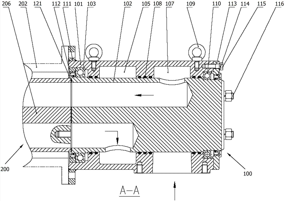
图2揭示了根据本实用新型的旋转密封装置的第一实施例的剖视结构。 Fig. 2 discloses the cross-sectional structure of the first embodiment of the rotary sealing device according to the present invention. the
图3a和图3b揭示了根据本实用新型的旋转密封装置的第一实施例的芯轴的结构。 Fig. 3a and Fig. 3b disclose the structure of the mandrel of the first embodiment of the rotary sealing device according to the present invention. the
图4揭示了根据本实用新型的旋转密封装置的第二实施例的剖视结构。 Fig. 4 discloses the cross-sectional structure of the second embodiment of the rotary sealing device according to the present invention. the
具体实施方式 Detailed ways
本实用新型旨在提出一种新型的旋转密封装置,能够适应冶金、造纸、铸造行业的需求。在冶金、造纸、铸造行业中,需要冷却或制冷功能的轴类设备,如双辊薄带连铸辊及其他的冶金机械、矿山机械以及造纸机械等轴体类旋转,此类辊轴向精度要求较高,载荷大并通有高压的液体作为润滑或冷却。本实用新型的旋转密封装置能承受高温、高压、高流量,且在中高速旋转过程中不发生泄露,对于轴类旋转件的轴向定位精度不造成影响,该装置能提高传动精度,提高旋转件的定位精度及轴承寿命,同时系统可靠性高。 The utility model aims at proposing a novel rotary sealing device, which can meet the needs of metallurgy, papermaking and casting industries. In metallurgy, papermaking, and foundry industries, shaft equipment that requires cooling or refrigeration functions, such as twin-roll thin strip continuous casting rolls and other metallurgical machinery, mining machinery, and papermaking machinery, etc. High requirements, high load and high pressure liquid as lubrication or cooling. The rotary sealing device of the utility model can withstand high temperature, high pressure, and high flow rate, and does not leak during medium and high-speed rotation, and does not affect the axial positioning accuracy of shaft rotating parts. The device can improve transmission accuracy and improve rotation The positioning accuracy and bearing life of the parts are improved, and the system reliability is high. the
本实用新型的旋转密封装置的设计原理如下:在设计旋转密封装置时,要将液体介质产生的不良影响降到最低,或将此不良影响转移到次要部件上,提高系统整体稳定性。本实用新型中,考虑到旋转密封的液体介质压力比较高,而轴端面积很大,由此产生的轴向力会导致轴向窜动,降低轴承的寿命,所以采用在旋转密封径向进、出冷却水的设计,将液体推力转移到轴的径向,提高系统稳定性。 The design principle of the rotary sealing device of the utility model is as follows: when designing the rotary sealing device, it is necessary to minimize the adverse effects of the liquid medium, or transfer the adverse effects to secondary components to improve the overall stability of the system. In the utility model, considering that the pressure of the liquid medium of the rotary seal is relatively high, and the area of the shaft end is large, the resulting axial force will cause axial movement and reduce the life of the bearing. , The cooling water design transfers the thrust of the liquid to the radial direction of the shaft and improves the stability of the system. the
图1a、图1b、图2、图3a和图3b揭示了根据本实用新型的旋转密封装置的第一实施例的结构,图4揭示了根据本实用新型的旋转密封装置的第二实施例的结构。 Fig. 1a, Fig. 1b, Fig. 2, Fig. 3a and Fig. 3b disclose the structure according to the first embodiment of the rotary sealing device of the present invention, and Fig. 4 discloses the structure of the second embodiment of the rotary sealing device according to the present invention structure. the
如图所示,本实用新型揭示了一种旋转密封装置100,连接到旋转零件200。该旋转密封装置100包括:芯轴102、外壳101和唇形骨架密封圈,唇形骨架密封圈包括第一唇形骨架密封圈112和第二唇形骨架密封圈 114。芯轴102连接到旋转零件200的旋转轴206并与旋转轴206共同旋转。在一个实施例中,芯轴102通过四根螺杆116连接到旋转轴206,芯轴102和旋转轴206之间安装有密封垫121。外壳101为铜合金或者不锈钢材质。外壳101的第一端连接到旋转零件200的机架202,在一个实施例中,外壳101通过法兰111连接到机架202。外壳101的第二端开口并由端盖113封闭,在一个实施例中,端盖113通过螺钉115连接到外壳101。芯轴102由两组支撑轴承,包括第一支撑轴承103和第二支撑轴承110支撑于外壳101内并与外壳101同轴。两组支撑轴承分别靠近外壳101的第一端和第二端设置。在一个实施例中,第一支撑轴承103和第二支撑轴承110是滚动轴承,两组支撑轴承安装在芯轴102和外壳101之间保持芯轴102和外壳101同轴。外壳101的内侧沿芯轴102的方向布置有进水腔107和出水腔105,进水腔107和出水腔105之间密封隔离。在一个实施例中,外壳101上在进水腔107的两侧安装有密封环108,进水腔107靠近出水腔105的一侧的密封环108的数量大于远离出水腔105的一侧的密封环108的数量。比如,在靠近出水腔105的一侧具有三组密封环108而在远离出水腔105的一侧具有两组密封环108。类似的,外壳101上在出水腔105的两侧安装有密封环108,出水腔105靠近进水腔107的一侧的密封环108的数量大于远离进水腔107的一侧的密封环108的数量。比如,在靠近进水腔107的一侧具有三组密封环108而在远离进水腔107的一侧具有两组密封环108。在一种布置方式中,在进水腔107和出水腔105之间布置三组密封环108,在进水腔107和出水腔105的两侧分别布置两组密封环108。进水腔107连接到进水管。出水腔105连接到出水管118。在一个实施例中,进水腔107的截面积大于进水管的截面积,比如,进水腔的截面积为进水管的截面积的2-5倍。出水管118设置在旋转密封装置100的侧面,与进水管的位置错开。唇形骨架密封圈包括第一唇形骨架密封圈112设置在第一支撑轴承103与旋转零件200之间、第二唇形骨架密封圈114设置在第二支撑轴承110与端盖113之间。在图示的实施例中,旋转密封装置100还包括吊装用的吊耳109,吊耳109通过螺纹安装在外壳101的上部。
As shown, the utility model discloses a
下面介绍本实用新型的具体实例,本实用新型的旋转密封装置与旋转零件相连,通过该装置向旋转零件内通入某种液体介质并导出,与此同时旋转件可以高速转动并在二者之间不发生所传输的液泄漏。该装置包括外壳、芯轴、支撑轴承以及密封圈。上述零件中,除了密封圈之外的零件均由铜、不锈钢或碳钢制造,不限制于某一种材料,可以是几种材料组合使用。而密封圈包括可以使O型圈或唇形骨架密封,也可以是二者组合使用。外壳通过支撑轴承与芯轴同轴,在外壳与芯轴之间采用密封圈实现旋转过程中的密封功能,其中,外壳内部沿着芯轴轴向有两个混水腔,分别是进水腔和出水腔。 The specific example of the utility model is introduced below. The rotary sealing device of the utility model is connected with the rotary part, through which a certain liquid medium is introduced into the rotary part and exported, and at the same time the rotary part can rotate at a high speed and between the two There is no leakage of the transferred fluid. The device includes a housing, a mandrel, a support bearing and a sealing ring. Among the above parts, the parts except the sealing ring are all made of copper, stainless steel or carbon steel, not limited to a certain material, and several materials can be used in combination. The sealing ring can seal the O-ring or the lip skeleton, or a combination of the two. The shell is coaxial with the mandrel through the support bearing, and a sealing ring is used between the shell and the mandrel to realize the sealing function during the rotation process. Among them, there are two mixed water chambers inside the shell along the axial direction of the mandrel. and outlet cavity. the
参照图1a、图1b、图2、图3a和图3b所示的第一实施例,旋转密封装置的芯轴102通过四根螺杆116与旋转零件的旋转轴206相连并随同后者旋转。芯轴102和旋转轴206之间有密封垫121,密封垫121的材质为橡胶或绝缘纸垫。外壳101沿着芯轴102轴向分别布置有进水腔107和出水腔105,在进水腔107和出水腔105之间沿芯轴102上安装有三道密封环108。在进水腔107和出水腔206的另外一侧分别沿芯轴102布置有两道密封环108。密封环108的形式都一致,为O型密封圈或唇形骨架密封或二者的组合使用。芯轴102和外壳101之间安装有支撑轴承,包括第一支撑轴承103和第二支撑轴承110。支撑轴承是滚动轴承,滚动轴承保持芯轴102和外壳101同轴。
Referring to the first embodiment shown in Figures 1a, 1b, 2, 3a and 3b, the
外壳101内部的进水腔107用于缓和即将进入旋转轴206的液体冲力,使其由于高速流动产生的气泡尽量少,利于提高液体与旋转轴之间的传热能力,所以进水腔107的截面积要大于进水管的截面积,进水腔107的截面积最佳为进水管截面积的2-5倍。为缩短该旋转密封装置100的总长度,出水管118设置在整个装置100的左侧,与进水管的位置错开,进水管设置在旋转密封装置100的下面,节省安装空间。
The
外壳101通过法兰111与机架202相连,并定位整个旋转密封装置100相对于旋转零件200以及旋转轴206的位置。外壳101比较大,所以材料最好采用铜合金或不锈钢材料等耐腐蚀材料,不需要经常更换。第一支撑轴承103外侧(与旋转零件200的旋转轴206的轴端相连处)设置有 唇形骨架密封圈112,相似地,在第二支撑轴承110的外侧,端盖113内嵌唇形骨架密封圈114。端盖113通过螺钉115与外壳101相连。
The
芯轴102有四个水孔,分别为两个进水孔和两个出水孔,分别对应于旋转部件的进、出水通道,芯轴内水孔的侧面加工有与混水腔相连的圆孔,如图3所示。芯轴102也可以是旋转轴206的一部分,尤其是在外壳101较重的情况下。旋转密封装置100还设置有吊装用的吊耳109,吊耳109通过螺纹安装在外壳101上部。
The
图4揭示了根据本实用新型的旋转密封装置的第二实施例的结构图。该旋转密封装置没有使用单独的芯轴与旋转轴相连,而是直接安装在旋转轴轴端,同样,外壳通过法兰与机架相连。 Fig. 4 discloses the structure diagram of the second embodiment of the rotary sealing device according to the present invention. The rotary sealing device does not use a separate mandrel to connect with the rotary shaft, but is directly installed on the shaft end of the rotary shaft. Likewise, the shell is connected to the frame through a flange. the
本实用新型的旋转密封装置结构紧凑,能够防止传输液体产生气泡,密封结构简单有效,适用于高速重载工况,具有可靠的密封性能,寿命长。该旋转密封装置的进水通道位于旋转轴的径向,能避免水压冲击对轴向定位精度造成影响。 The rotary sealing device of the utility model has a compact structure, can prevent transmission liquid from generating air bubbles, has a simple and effective sealing structure, is suitable for high-speed and heavy-load working conditions, has reliable sealing performance, and has a long service life. The water inlet channel of the rotary sealing device is located in the radial direction of the rotating shaft, which can avoid the impact of water pressure on the axial positioning accuracy. the
Claims (9)
Priority Applications (1)
| Application Number | Priority Date | Filing Date | Title |
|---|---|---|---|
| CN201220414129.3U CN202851952U (en) | 2012-08-20 | 2012-08-20 | Rotary sealing device |
Applications Claiming Priority (1)
| Application Number | Priority Date | Filing Date | Title |
|---|---|---|---|
| CN201220414129.3U CN202851952U (en) | 2012-08-20 | 2012-08-20 | Rotary sealing device |
Publications (1)
| Publication Number | Publication Date |
|---|---|
| CN202851952U true CN202851952U (en) | 2013-04-03 |
Family
ID=47983157
Family Applications (1)
| Application Number | Title | Priority Date | Filing Date |
|---|---|---|---|
| CN201220414129.3U Expired - Lifetime CN202851952U (en) | 2012-08-20 | 2012-08-20 | Rotary sealing device |
Country Status (1)
| Country | Link |
|---|---|
| CN (1) | CN202851952U (en) |
Cited By (2)
| Publication number | Priority date | Publication date | Assignee | Title |
|---|---|---|---|---|
| CN103878343A (en) * | 2014-04-14 | 2014-06-25 | 苏州明志科技有限公司 | Self-sealing casting bent pipe for low-pressure tilting casting |
| CN109268502A (en) * | 2018-12-03 | 2019-01-25 | 江苏丰东热技术有限公司 | A kind of roller stick sealing mechanism and roller stick sealing system |
-
2012
- 2012-08-20 CN CN201220414129.3U patent/CN202851952U/en not_active Expired - Lifetime
Cited By (3)
| Publication number | Priority date | Publication date | Assignee | Title |
|---|---|---|---|---|
| CN103878343A (en) * | 2014-04-14 | 2014-06-25 | 苏州明志科技有限公司 | Self-sealing casting bent pipe for low-pressure tilting casting |
| CN109268502A (en) * | 2018-12-03 | 2019-01-25 | 江苏丰东热技术有限公司 | A kind of roller stick sealing mechanism and roller stick sealing system |
| CN109268502B (en) * | 2018-12-03 | 2024-03-22 | 江苏丰东热技术有限公司 | Roller rod sealing mechanism and roller rod sealing system |
Similar Documents
| Publication | Publication Date | Title |
|---|---|---|
| CN202348756U (en) | Double mechanical sealing structure | |
| CN110274022B (en) | Front main bearing combined sealing device of horizontal scraper centrifuge | |
| CN203009832U (en) | Rotary seal device suitable for high-flow and high-pressure working conditions | |
| CN214789035U (en) | High-temperature high-pressure mechanical sealing device for composite power groove | |
| CN109681637A (en) | A kind of daul-side dry round gas seal for screw vacuum dry pump | |
| CN105065276A (en) | Combined type sealing device of dry screw vacuum pump | |
| CN103629357A (en) | Sealing mechanism for vane type rotary valve | |
| CN201599202U (en) | High temperature and high pressure process pump | |
| CN203067781U (en) | High-speed low-friction mass-flow novel liquid rotating sealing device | |
| CN211259945U (en) | Rotary joint | |
| CN108825507A (en) | A kind of list double suction mixed type middle open centrifugal pump | |
| CN206175664U (en) | Transmission shafting doublestage dynamic seal system | |
| CN107654377A (en) | The gland seal device of oil free screw machine | |
| CN101936434B (en) | Rotating joint | |
| CN100370146C (en) | Mechaniclly sealing device of immersible pump | |
| CN201057270Y (en) | Packless seal device | |
| CN210715953U (en) | Heavy machinery sealing device | |
| CN213145694U (en) | Rotary joint assembly for hot rolling coiling machine | |
| CN112128491B (en) | Annular groove sealing type rotary joint | |
| CN202348682U (en) | Slow-rotary-speed corrosion-resisting wear-resisting centrifugal pump | |
| CN103321946B (en) | It is automatically adjusted no-water sealing device | |
| CN208871034U (en) | A kind of hydrogen cooled generator double fluid ring sealing bearing bush inhibiting Seal Oil channelling flow | |
| CN223062656U (en) | Multistage centrifugal pump structure | |
| CN207363896U (en) | Without cooling high temperature and pressure heat-exchanger pump | |
| CN209430470U (en) | A filter press pump with improved seal life |
Legal Events
| Date | Code | Title | Description |
|---|---|---|---|
| C14 | Grant of patent or utility model | ||
| GR01 | Patent grant | ||
| CX01 | Expiry of patent term |
Granted publication date: 20130403 |
|
| CX01 | Expiry of patent term |