CN202850600U - Handle mounting base for rotating automatic door - Google Patents
Handle mounting base for rotating automatic door Download PDFInfo
- Publication number
- CN202850600U CN202850600U CN 201220446890 CN201220446890U CN202850600U CN 202850600 U CN202850600 U CN 202850600U CN 201220446890 CN201220446890 CN 201220446890 CN 201220446890 U CN201220446890 U CN 201220446890U CN 202850600 U CN202850600 U CN 202850600U
- Authority
- CN
- China
- Prior art keywords
- automatic door
- base
- handle
- handle mounting
- utility
- Prior art date
- Legal status (The legal status is an assumption and is not a legal conclusion. Google has not performed a legal analysis and makes no representation as to the accuracy of the status listed.)
- Expired - Fee Related
Links
- 241000276425 Xiphophorus maculatus Species 0.000 claims description 3
- 238000009434 installation Methods 0.000 abstract description 3
- 238000005516 engineering process Methods 0.000 description 2
- 230000004048 modification Effects 0.000 description 2
- 238000012986 modification Methods 0.000 description 2
Images

Landscapes
- Extensible Doors And Revolving Doors (AREA)
Abstract
The utility model discloses a handle mounting base for a rotating automatic door. The handle mounting base comprises a base (1), wherein two support arms (2) are arranged on the base (1) and arranged extending out of one side of the base (1) in an inclined mode. Handle mounting holes (3) are formed in the support arms (2), and are the same in size between the two support arms (2) and have the same axis. The handle mounting base for the rotating automatic door can be well attached to the rotating automatic door at the folding time, not prone to collision, hooking and other accidents, not prone to damage on human body, and has the advantages of being reliable in installation, simple in structure, and low in cost.
Description
Technical field
The utility model relates to a kind of handle mount pad for rotational automatic door.
Background technology
The handle mount pad that prior art is used for rotational automatic door generally comprises the sleeve pipe on base and the base, and sleeve pipe is located on the center line of base, and handle then is installed on the sleeve pipe by turning cylinder.But because sleeve pipe is located on the center line of base, therefore the handle of rotational automatic door can not be fitted rotational automatic well when folding, easily bumps, the accident such as hook, easily human body is damaged.
The utility model content
The technical problems to be solved in the utility model provides a kind of handle of rotational automatic door can fit rotational automatic well when folding, be not easy to bump, the accident such as hook, be not easy human body is damaged, the handle mount pad that is used for rotational automatic door reliable, simple in structure, with low cost is installed.
For solving the problems of the technologies described above, the technical solution adopted in the utility model is:
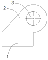
A kind of handle mount pad for rotational automatic door, comprise base, described base is provided with to a skew back to two supporting arms that stretch out layout, and described supporting arm is provided with the handle installing hole, and size is identical and axis is identical between the handle installing hole of described two supporting arms.
As further improvement in the technical proposal:
Described supporting arm is platy structure.
The bottom of described base is provided with stopper slot, and the opening direction of described stopper slot is mutually vertical with the axis of described handle installing hole.
The utlity model has following advantage:
Base of the present utility model is provided with to a skew back to two supporting arms that stretch out layout, supporting arm is provided with the handle installing hole, size is identical and axis is identical between the handle installing hole of two supporting arms, because supporting arm of the present utility model is to base one skew back to stretching out layout, therefore the handle of the rotational automatic door of the utility model can be fitted rotational automatic well when folding, be not easy to bump, the accident such as hook, be not easy human body is damaged, have advantages of that installation is reliable, simple in structure, with low cost.
Description of drawings
In order to be illustrated more clearly in the utility model embodiment or technical scheme of the prior art, the below will do to introduce simply to the accompanying drawing of required use in embodiment or the description of the Prior Art, apparently, accompanying drawing in the following describes only is embodiment more of the present utility model, for those of ordinary skills, under the prerequisite of not paying creative work, can also obtain according to these accompanying drawings other accompanying drawing.
Fig. 1 is the perspective view of the utility model embodiment.
Fig. 2 is the side-looking structural representation of the utility model embodiment.
Marginal data: 1, base; 2, supporting arm; 3, handle installing hole; 4, stopper slot.
The specific embodiment
Below in conjunction with accompanying drawing preferred embodiment of the present utility model is described in detail, thereby so that advantage of the present utility model and feature can be easier to be it will be appreciated by those skilled in the art that protection domain of the present utility model is made more explicit defining.
As depicted in figs. 1 and 2, the handle mount pad that the present embodiment is used for rotational automatic door comprises base 1, base 1 is provided with to a skew back to two supporting arms 2 that stretch out layout, and supporting arm 2 is provided with between the handle installing hole 3 of 3, two supporting arms 2 of handle installing hole that size is identical and axis is identical.The handle of the rotational automatic door of the present embodiment rotational automatic door of can fitting well when folding is not easy to bump, the accident such as hook, is not easy human body is damaged, and has advantages of that installation is reliable, simple in structure, with low cost.
In the present embodiment, supporting arm 2 is platy structure, and intensity is reliable and save material.
In the present embodiment, the bottom of base 1 is provided with stopper slot 4, and the opening direction of stopper slot 4 is mutually vertical with the axis of handle installing hole 3, can prevent effectively that base 1 from sliding along the axis of handle installing hole 3.
The above only is preferred embodiment of the present utility model, and protection domain of the present utility model is not limited in above-mentioned embodiment, and every technical scheme that belongs to the utility model principle all belongs to protection domain of the present utility model.For a person skilled in the art, some improvements and modifications of under the prerequisite that does not break away from principle of the present utility model, carrying out, these improvements and modifications also should be considered as protection domain of the present utility model.
Claims (3)
1. handle mount pad that is used for rotational automatic door, it is characterized in that: comprise base (1), described base (1) is provided with to a skew back to two supporting arms (2) that stretch out layout, described supporting arm (2) is provided with handle installing hole (3), and size is identical and axis is identical between the handle installing hole (3) of described two supporting arms (2).
2. the handle mount pad for rotational automatic door according to claim 1, it is characterized in that: described supporting arm (2) is platy structure.
3. the handle mount pad for rotational automatic door according to claim 2, it is characterized in that: the bottom of described base (1) is provided with stopper slot (4), and the opening direction of described stopper slot (4) is mutually vertical with the axis of described handle installing hole (3).
Priority Applications (1)
| Application Number | Priority Date | Filing Date | Title |
|---|---|---|---|
| CN 201220446890 CN202850600U (en) | 2012-09-04 | 2012-09-04 | Handle mounting base for rotating automatic door |
Applications Claiming Priority (1)
| Application Number | Priority Date | Filing Date | Title |
|---|---|---|---|
| CN 201220446890 CN202850600U (en) | 2012-09-04 | 2012-09-04 | Handle mounting base for rotating automatic door |
Publications (1)
| Publication Number | Publication Date |
|---|---|
| CN202850600U true CN202850600U (en) | 2013-04-03 |
Family
ID=47981812
Family Applications (1)
| Application Number | Title | Priority Date | Filing Date |
|---|---|---|---|
| CN 201220446890 Expired - Fee Related CN202850600U (en) | 2012-09-04 | 2012-09-04 | Handle mounting base for rotating automatic door |
Country Status (1)
| Country | Link |
|---|---|
| CN (1) | CN202850600U (en) |
-
2012
- 2012-09-04 CN CN 201220446890 patent/CN202850600U/en not_active Expired - Fee Related
Similar Documents
| Publication | Publication Date | Title |
|---|---|---|
| TW200516372A (en) | Combined supporting base | |
| CN203199507U (en) | Universal supporting leg | |
| CN202850704U (en) | Fixing seat for mounting automatic door glass support leg | |
| CN203607960U (en) | A clamping-groove-connection-type motor installation seat | |
| CN202764774U (en) | Integrated metal handle component for bus | |
| CN202832000U (en) | Slide mounting base for automatic door | |
| CN203131700U (en) | PVC lamp shield | |
| CN202428113U (en) | USB (universal serial bus) vibrating mirror type automatic welding machine | |
| CN202509918U (en) | Short door hinge for furniture movable door | |
| CN202566958U (en) | Computer desk with desk lamp | |
| CN202831934U (en) | Shaft connection installation base for rotating type automatic door | |
| CN209294672U (en) | A kind of display device | |
| CN202831942U (en) | Pulley installation base for automatic door | |
| CN203504911U (en) | Control cabinet end plate suspension installation device | |
| CN202850790U (en) | Rotating type automatic door outer frame connector | |
| CN203126599U (en) | Pull handle mounting base for public transport mean | |
| CN203233610U (en) | Side-hanged electric cabinet for transporter in well | |
| CN202773219U (en) | Improved cabinet handle | |
| CN207345652U (en) | A kind of concrete mixer truck pipeline connection fixing base | |
| CN207005076U (en) | A kind of non-conventional type joint | |
| CN205886508U (en) | A tower tray lock ring in single deck tape -recorder groove | |
| CN202850750U (en) | Doorframe fixing device for hotel automatic door | |
| CN202832091U (en) | Door frame protection device for automatic glass door | |
| CN206179472U (en) | Bicycle advertisement board | |
| CN202008112U (en) | Lamp mounting structure |
Legal Events
| Date | Code | Title | Description |
|---|---|---|---|
| C14 | Grant of patent or utility model | ||
| GR01 | Patent grant | ||
| C17 | Cessation of patent right | ||
| CF01 | Termination of patent right due to non-payment of annual fee |
Granted publication date: 20130403 Termination date: 20130904 |