The column suspension member that a kind of inversion type energy-saving curtain wall is used
Technical field
The utility model relates to a kind of simple in structure, and the column suspension member that conveniently installation, and the good inversion type energy-saving curtain wall of pinpoint heat-proof quality is used belongs to curtain wall component technology field.
Background technology
The shell system of conventional member curtain wall is to be placed in indoorly, that is to say the inboard at glass, realizes the placing restrictions on of glass carried out the installation curtain wall of outer deckboard again by clip plate.Said structure places restrictions on the following problem that certainly exists just.
1, glass plate can only be in outdoor mounted, and the replacing of glass quite bothers in use, the maintenance process.Highrise building must be by hanging blue could the realization, often causes the expense of supporting facility to be far longer than the expense of damaged glass, becomes the interior insoluble research and development problem of industry all the time.
2, along with the expanding economy people are also more and more to the requirement of curtain wall decorative effect.Usually the requirement of the large scale of outer cover plate also progressively increased.Because the skeleton of conventional curtain wall is indoor, the requirement of structural calculation has increased the thickness of curtain wall so that the size of main stressed member is quite large; The significantly decoration requirement of outer cover plate also to be arranged in addition on this basis, must cause a lot of wastes.
3, because the stand under load situation of column, crossbeam is different, so that both sizes differ larger, so that indoor decorative cover has larger poor position, inconvenience and difficulty have been brought to interior decoration.
A kind of photovoltaic glass curtain wall has appearred in 4, this year, and described photoelectric curtain wall is exactly on existing curtain wall basis, increases solar panel, and the electric energy that then with wire solar energy is transformed is directed on the electricity consumption facility.Existing curtain wall, arranging of wire is cumbersome, must increase the wire-protecting facility at existing curtain wall, causes cost to increase.
For this reason, we have opened a kind of inversion type energy-saving curtain wall, and be provided with a kind of simple in structure, the convenient installation, and the column suspension member used of the good inversion type energy-saving curtain wall of pinpoint heat-proof quality.
The utility model content
The utility model purpose is to provide a kind of simple in structure in order to overcome the deficiencies in the prior art, the column suspension member that conveniently installation, and the good inversion type energy-saving curtain wall of pinpoint heat-proof quality is used.
For achieving the above object, the technical solution adopted in the utility model is: the column suspension member that a kind of inversion type energy-saving curtain wall is used comprises column peg main body; The T-shaped setting of described column suspension member main body; Be provided with the suspension part on the upper surface of described column peg main body; Be provided with screwed hole on the described suspension part; Be provided with wire casing on the lateral surface of the bottom of described column peg main body; Be provided with heat insulation groove on the described column peg main body; Be provided with isolation layer in the described heat insulation groove.
Preferably, described suspension part is spherical in shape.
Because the utilization of technique scheme, the utility model compared with prior art has following advantages:
The column suspension member that inversion type energy-saving curtain wall described in the utility model is used is provided with the suspension part on the upper surface of described column peg main body, makes things convenient in suspension and the column hanging seat, and fixes by screwed hole; Be provided with wire casing on the lateral surface of the bottom of described column peg main body simultaneously, to being screwed into screw the wire casing, can fix with column, and accurately locate; Be provided with heat insulation groove on the described column peg main body; Be provided with isolation layer in the described heat insulation groove, heat-proof quality is good; The utility model is simple in structure, the convenient installation.
Description of drawings
Below in conjunction with accompanying drawing technical solutions of the utility model are described further:
Accompanying drawing 1 is the sectional view of inversion type energy-saving curtain wall described in the utility model;
Accompanying drawing 2 is the schematic diagram behind the D-D sectional view 90-degree rotation in the accompanying drawing 1;
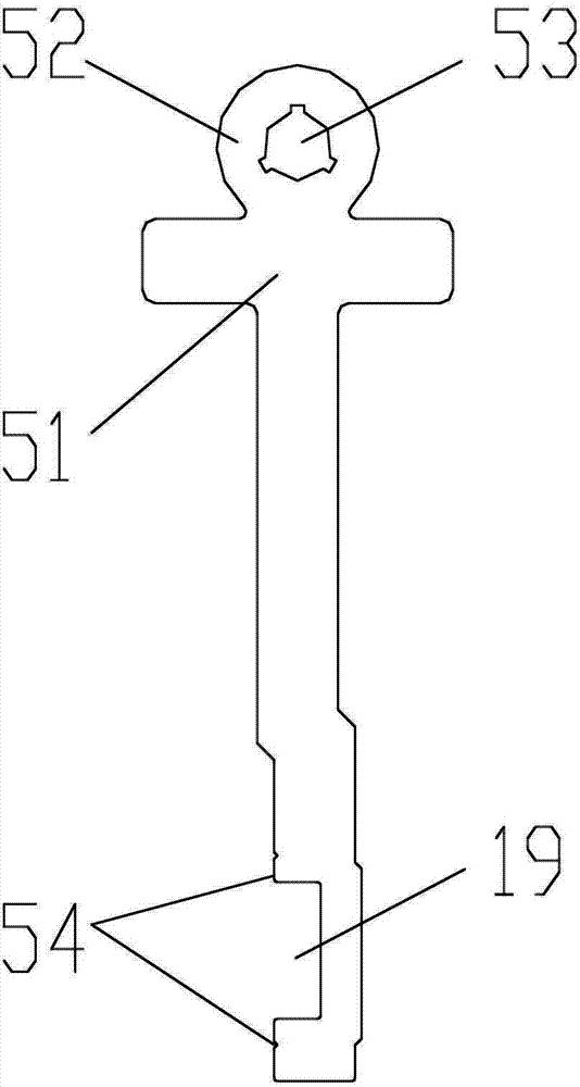
The schematic diagram of the column suspension member that accompanying drawing 3 is used for inversion type energy-saving curtain wall described in the utility model;
Wherein: 1, built-in fitting; 2, other plate; 3, column hanging seat; 4, bolt assembly; 5, column suspension member; 6, clip plate; 7, outer cover plate; 8, rubber weather strip; 9, glass; 10, column; 11, column stem stem; 12, screw; 13, tank shutoff; 14, half clip plate; 15, crossbeam; 16, drain hole; 17, isolation layer; 19, heat insulation groove; 51, column peg main body; 52, suspension part; 53, screwed hole; 54, to wire casing.
The specific embodiment
Described in the utility model a kind of inversion type energy-saving curtain wall shown in accompanying drawing 1,2 comprises built-in fitting 1, column hanging seat 3, column suspension member 5, clip plate 6, outer cover plate 7, glass 9, column 10, crossbeam 15; The front end of described built-in fitting 1 is imbedded in the body of wall (for illustrating); Be provided with the other plate 2 that a pair of interval arranges on the rear end face of described built-in fitting 1; In the space by described column hanging seat 3 is arranged between the plate 2; The upper end of described column suspension member 5 is arranged on the column hanging seat 3, and the lower end of described column suspension member 5 is arranged on the column 10; Be provided with isolation layer 17 between described column suspension member 5 and the column 10; The end of described glass 9 is arranged on the inboard of column 10, and pushes down with clip plate 6; The both sides of described column 10 are provided with glass 9; Described clip plate 6 column 10 that collapsed, and be fixed on the column 10 with screw 12; Described crossbeam 15 and column 10 handing-over; Described glass 9 ends are provided with tank shutoff 13, and are arranged in the groove (not marking) on the crossbeam 15; The medial end of described crossbeam 15 is provided with half clip plate 14; Described half clip plate 14 is pressed in the end of the glass 9 that is arranged on crossbeam 15 soffits; Be provided with drain hole 16 on the sidepiece of described groove; Described drain hole 16 makes groove be communicated with crossbeam 15 inner chambers.The outside buckle of described clip plate 6 has outer cover plate 7.The outside buckle of described half clip plate 14 has outer cover plate 7.Be provided with bolt assembly 4 on the described other plate 2, column hanging seat 3 is passed in the end of described bolt assembly 4, and withstands column suspension member 5 sidewalls; Position in order to adjusting post suspension member 5.Upper end or bottom in the described column 10 are provided with column stem stem 11; Column 10 is stretched out in the end of described column stem stem 11, in order to be socketed with the column 10 that links to each other.Described glass 9 is provided with rubber weather strip 8 with the contact surface of column 10; Described glass 9 is provided with rubber weather strip 8 with the contact surface of crossbeam 15.Described glass 9 is provided with rubber weather strip with the contact surface of clip plate 6.
May ponding in the use procedure further groove, ponding can enter by drain hole 16 inner chamber of crossbeam 15, flow out from the lap-joint of crossbeam 15 at last, thereby it is indoor to avoid ponding to flow into.
In addition, the spaces in the outer cover plate 7 can be used for away wire, thereby are highly suitable for photovoltaic curtain wall, and do not need the facility of extra guardwire.Thereby cost of manufacture is low.
The column suspension member of using for a kind of inversion type energy-saving curtain wall described in the utility model as shown in Figure 3 comprises column peg main body 51; Described column suspension member main body 51 T-shaped settings; Be provided with suspension part 52 on the upper surface of described column peg main body 51; Described suspension part 52 is spherical in shape, the convenient adjusting; Be provided with screwed hole 53 on the described suspension part 52; Be provided with wire casing 54 on the lateral surface of the bottom of described column peg main body 51; Be provided with heat insulation groove 19 on the described column peg main body 51; Be provided with the isolation layer (not shown) in the described heat insulation groove 19.
The column suspension member that inversion type energy-saving curtain wall described in the utility model is used is provided with suspension part 52 on the upper surface of described column peg main body 51, in convenient suspension and the column hanging seat 3, and fixing by screwed hole 53; Be provided with wire casing 54 on the lateral surface of the bottom of described column peg main body 51 simultaneously, to being screwed into screw the wire casing 54, can fix with column 10, and accurately locate; Be provided with heat insulation groove 19 on the described column peg main body 51; Be provided with isolation layer in the described heat insulation groove 19, heat-proof quality is good; The utility model is simple in structure, the convenient installation.
Below only be concrete exemplary applications of the present utility model, protection domain of the present utility model is not constituted any limitation.All employing equivalents or equivalence are replaced and the technical scheme of formation, all drop within the utility model rights protection scope.